EP1577060A2 - Ausklinkwerkzeug - Google Patents
Ausklinkwerkzeug Download PDFInfo
- Publication number
- EP1577060A2 EP1577060A2 EP05006044A EP05006044A EP1577060A2 EP 1577060 A2 EP1577060 A2 EP 1577060A2 EP 05006044 A EP05006044 A EP 05006044A EP 05006044 A EP05006044 A EP 05006044A EP 1577060 A2 EP1577060 A2 EP 1577060A2
- Authority
- EP
- European Patent Office
- Prior art keywords
- notching
- cutting
- processing
- tool according
- tool
- Prior art date
- Legal status (The legal status is an assumption and is not a legal conclusion. Google has not performed a legal analysis and makes no representation as to the accuracy of the status listed.)
- Granted
Links
Images
Classifications
-
- B—PERFORMING OPERATIONS; TRANSPORTING
- B24—GRINDING; POLISHING
- B24D—TOOLS FOR GRINDING, BUFFING OR SHARPENING
- B24D7/00—Bonded abrasive wheels, or wheels with inserted abrasive blocks, designed for acting otherwise than only by their periphery, e.g. by the front face; Bushings or mountings therefor
- B24D7/18—Wheels of special form
-
- B—PERFORMING OPERATIONS; TRANSPORTING
- B23—MACHINE TOOLS; METAL-WORKING NOT OTHERWISE PROVIDED FOR
- B23C—MILLING
- B23C3/00—Milling particular work; Special milling operations; Machines therefor
- B23C3/12—Trimming or finishing edges, e.g. deburring welded corners
- B23C3/128—Trimming or finishing edges of doors and windows
-
- B—PERFORMING OPERATIONS; TRANSPORTING
- B23—MACHINE TOOLS; METAL-WORKING NOT OTHERWISE PROVIDED FOR
- B23C—MILLING
- B23C5/00—Milling-cutters
- B23C5/02—Milling-cutters characterised by the shape of the cutter
- B23C5/08—Disc-type cutters
-
- B—PERFORMING OPERATIONS; TRANSPORTING
- B24—GRINDING; POLISHING
- B24B—MACHINES, DEVICES, OR PROCESSES FOR GRINDING OR POLISHING; DRESSING OR CONDITIONING OF ABRADING SURFACES; FEEDING OF GRINDING, POLISHING, OR LAPPING AGENTS
- B24B9/00—Machines or devices designed for grinding edges or bevels on work or for removing burrs; Accessories therefor
- B24B9/02—Machines or devices designed for grinding edges or bevels on work or for removing burrs; Accessories therefor characterised by a special design with respect to properties of materials specific to articles to be ground
- B24B9/06—Machines or devices designed for grinding edges or bevels on work or for removing burrs; Accessories therefor characterised by a special design with respect to properties of materials specific to articles to be ground of non-metallic inorganic material, e.g. stone, ceramics, porcelain
- B24B9/08—Machines or devices designed for grinding edges or bevels on work or for removing burrs; Accessories therefor characterised by a special design with respect to properties of materials specific to articles to be ground of non-metallic inorganic material, e.g. stone, ceramics, porcelain of glass
- B24B9/14—Machines or devices designed for grinding edges or bevels on work or for removing burrs; Accessories therefor characterised by a special design with respect to properties of materials specific to articles to be ground of non-metallic inorganic material, e.g. stone, ceramics, porcelain of glass of optical work, e.g. lenses, prisms
-
- B—PERFORMING OPERATIONS; TRANSPORTING
- B23—MACHINE TOOLS; METAL-WORKING NOT OTHERWISE PROVIDED FOR
- B23C—MILLING
- B23C2210/00—Details of milling cutters
- B23C2210/24—Overall form of the milling cutter
- B23C2210/244—Milling cutters comprised of disc-shaped modules or multiple disc-like cutters
Definitions
- the invention relates to a notching tool, in particular for Processing of plastic or aluminum profiles, comprising a tool body formed by one or more bodies, the at least one first processing area for Notching a first contour area and at least one second processing area for notching a second Has contour area.
- EP 1 422 005 A1 discloses a method and a device for edge processing of a plastic optical lens as well a combination tool known.
- the combination tool has different processing areas, by means of which in different operations edge processing, especially plastic eyeglass lenses, can be done.
- Notching tool in the sense of the present patent application is the combination tool according to the European patent application Not insertable.
- the document DE 102 55 058 A1 is the priority German patent application to the previously mentioned European patent application. Are content both documents congruent.
- the document DE 35 42 258 shows a tool for the cutting Machining, preferably as a milling and grinding tool.
- the milling or grinding tool is capable of in to mill and grind one operation at a time.
- the tool consists of a front machining direction arranged insert and a directly behind it located support plate. Relative to the diameter of the Spanes to be lifted Spanes is the support plate in diameter relative to the cutting contour of the insert easily protruding so that they have the same contour of the insert following only the grinding takes over.
- Ausklinkmaschinemaschinemaschinee similar type are known from DE 202 18 724 U1 known.
- This is a rotary notching tool discloses whose profile generating surface with Diamonds are occupied to ensure the highest possible quality of production achieve and tool life while reducing to increase the processing time.
- the wears Processing mainly of plastic profiles with Diamonds did not adhere to all the requirements of abrasive wheels the highest possible quality of production. It has become shown that this form of editing, especially at chamfering, to unsatisfactory results leads, as it leads to a chamfering by the use of Diamond tools can come.
- first processing area geometrically indefinite cutting and the second processing area at least one geometrically determined Cutting edge has.
- machining methods are generally of the separation assigned. This includes machining with geometrically indeterminate Cutting, in particular, grinding, chipping geometrically determined cutting edge, however, includes, among other things turning, milling, planing, pushing and broaching.
- the invention is characterized in particular by the fact that by means of the Ausklinkwerkmaschinemaschinees plastic profiles in particular in one operation with regard to the processing certain and indefinite cutting can be done.
- the notching tool either according to the desired contour shape.
- this it is also possible, according to one advantageous development of the invention, this to make different contours customizable. With that Different contour contours on workpieces in one single operation. All from the state of the Technically known tools can not do this in one operation. Either it is not possible to have different contours or it is necessary to get the tool or the To set up a workpiece for the respective machining cycle, to carry out the desired processing. This requires a considerable amount of time. This one will Saved by the invention now.
- the tool body of several is formed concentrically arranged basic bodies, which are arranged on a driven shaft and with this rotate.
- the tool body thus combines in this Case the procedures grinding (geometrically indefinite cutting edge) and milling (geometrically determined cutting edge) with each other.
- This type of tooling offers advantages for a fast Repair of the tool body and the possibility of the tool body the contour to be produced by substitution of different basic bodies with different shaped processing areas adapt.
- the Base body releasably connected to the shaft, they can but, if this seems advantageous, also in one piece with be connected to the shaft.
- the first processing area is according to the invention of a with Diamonds occupied, the workpiece facing outer surface of the Tool body formed.
- the processing with diamonds leads to a good manufacturing quality and at the same time ensures high tool life and rapid machining of the workpiece.
- the second processing area is preferably at least one made of tungsten carbide produced cutting plate, the has at least one geometrically determined cutting edge.
- Cutting inserts made of tool or high-speed steels
- Cutting ceramics or polycrystalline cutting materials can be used in also be advantageous in certain cases.
- first processing area and the second processing area are designed so that they are different desired contours of a workpiece are customizable, in particular such that the machining of the workpiece in one operation is possible. That's the way it is, for example possible to design the notching tool so that certain Areas are made adjustable or changeable. This can be both in diameter, but this can also be in height happen. For example, intermediate pieces may be provided Be that to achieve a specific contour before editing be added. In the further is also one Adjusting the angle of incidence of the cutting provided so that Different variants are feasible. This is possible the known from the prior art solutions of combination tools the plastic processing can not afford. Rather, these have compared to the now presented improved variant of the invention solid, non-adjustable Cutting areas or grinding areas.
- At least one of the main body is formed by a cutting plate.
- the Cutting plate and one of the body made in one piece.
- the cutting plate can so in a particularly simple manner on the Shaft are pushed and as part of the tool body the form second processing area.
- Ausklinkwerkmaschines invention provides that the inserts with one of the Body are releasably or permanently connected.
- the cutting plates be in a permanent connection with one of the Body preferably soldered, welded or shrunk.
- the inserts with a body solvable connected they are usually bolted. So can the tool body optimized for the respective application become.
- Such an embodiment also has the advantage that when damaged a geometrically determined Cut them quickly and quickly by replacing the insert can be easily replaced.
- the shape of the second contour area to be changed the tool body the new contour by replacing an insert in be adapted efficiently.
- a development of the invention is characterized by that the insert is an indexable insert, which with one of the base body is detachably connected.
- the usage of Indexable inserts is on the one hand cheap and allows for Others a quick and easy adjustment of the tool body, especially in case of damage to a geometric certain cutting edge.
- the cutting plate releasably connected to one of the main body is, it is advantageous that the cutting board over a releasable lock is attached to one of the base body and displaceable relative to the base body, displaceable or rotatable is stored. So is a adjustability of individual inserts and thus the geometrically determined Cutting on the body allows. This will be in particular a simple and advantageous way that achieves that Modification of the tool body for the purpose of changing the second contour area merely by loosening a cutting plate, Adjusting the cutting plate relative to the base body and again detecting the cutting plate can be realized can. For example, a change of one by the Cutting plate on the workpiece caused bevel angle or a Contour depth or shape can be realized without losing one To remove body from the shaft. The adjustability can be approximately through several staggered holes or be realized by slots in the cutting plate.
- the respective intended direction of cutting are opposed.
- a Machining the workpiece with the first processing area is by its design with geometrically indefinite Cutting easily in several directions possible. thats why it is desirable that the second processing area, for example, when editing with a rotatory working Ausklinktechnikmaschine, is designed such that with him both a left-handed and a right-handed Editing is possible.
- the geometrically determined cutting edges with opposite intended cutting directions can while being arranged on an insert, for example or they are roughly in the opposite direction Indexable inserts detachable or unsolvable with one of the basic bodies connected.
- a cutting plate of course can also be made in several parts. So is in the sense
- the invention for example, a carrier with an on this arranged and fixed indexable insert, as is is common, for example, with lathe tools, the term insert summarize.
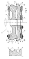
- Figure 1 is an inventive notching tool with a Tool body 2 and associated workpiece 7 in four variants A, B, C, D of the invention shown greatly simplified.
- the shown variants A, B, C, D are here for illustrative purposes model shown on a tool body 2. All illustrated variants A, B, C, D cause the same Machining of the workpiece 7.
- the tool body 2 is made of several basic bodies 1, which are concentric with each other on a driven Shaft be pushed and rotate with it, taking they are preferably releasably connected to the shaft.
- the tool body 2 points to an outer surface facing the workpiece 7 a first processing area 3 with geometrically indefinite Cutting 5 and a second processing area. 4 with geometrically determined cutting 6.
- the first editing area 3 latches out of the workpiece 7 a first Contour area 3 'off
- the second processing area latches out the workpiece 7 a second contour region 4 'from.
- the second Contour area 4 ' is in the illustrated case of two outer Chamfers formed.
- All four illustrated variants A, B, C, D show a Cutting plate 8, each at least one geometrically determined Cutting edge 6, which has the second processing area 4 forms and the second contour region 4 'from the workpiece 7 disengages. In general, however, are more geometric certain cutting edges 6 over the circumference of the tool body 2 in the second processing area 4 distributed. To the function of Notching tool from the direction of rotation of the tool body 2 can make independent, in an advantageous development the invention determines the cutting plate geometrically Cutting 6 for both directions of rotation, ie with opposite Proper cutting directions, have.
- Variant A shows a cutting plate 8, with one of the main body 1 is connected, wherein the base body 1, the Cutting plate 8 carries, at the same time a part of the first Processing area 3 forms.
- the cutting plate 8 is preferably designed as an indexable insert, which is detachable on the Base body 1 is attached. Preferably, several such Cutting plates 8 at regular intervals over the circumference of the Basic body 1 arranged.
- the cutting plate 8 is preferably directly via a screw connection or indirectly mounted on the base body 1 via a cutting plate carrier.
- the cutting plate 8 is a single annular Element formed that with one of the main body 1 is connected and over its circumference at least one geometrically has certain cutting edge 6, which is the second processing area 4 forms. Again, the cutting plate 8 with a the base body 1 is connected, which faces on a workpiece 7 Outer surface at least a part of the first processing area 3 form.
- Variant C represents an insert 8, which with a Basic body 1 is connected, concentric to the other Basic bodies 1 is pushed onto the shaft, detachable with the Wave is connected and with this and the other basic bodies 1 rotates.
- the cutting plate 8 is preferably in variant C. formed by an annular element.
- the connection between cutting plate 8 and body 1 is preferably designed as a permanent connection, which in particular solder or Welding involves, but is also a shrinking the annular cutting plate 8 on the body conceivable.
- the last illustrated variant D shows similar to the variant C. a snow blade 8, but these in variant D in one piece executed with the main body 1.
- Basic body 1 and Cutting plate 8 thus form a unit.
Landscapes
- Engineering & Computer Science (AREA)
- Mechanical Engineering (AREA)
- Chemical & Material Sciences (AREA)
- Ceramic Engineering (AREA)
- Inorganic Chemistry (AREA)
- Milling Processes (AREA)
- Food-Manufacturing Devices (AREA)
Abstract
Description
- Fig. 1
- ein erfindungsgemäßes Ausklinkwerkzeug mit einem Werkzeugkörper in vier möglichen Varianten A, B, C, D in stark vereinfachter Darstellung.
Claims (10)
- Ausklinkwerkzeug, insbesondere zur Bearbeitung von Kunststoff- oder Aluminiumprofilen, umfassend einen von einem oder mehreren Grundkörpern (1) gebildeten Werkzeugkörper (2), der zumindest einen ersten Bearbeitungsbereich (3) zum Ausklinken eines ersten Konturbereiches (3') und zumindest einen zweiten Bearbeitungsbereich (4) zum Ausklinken eines zweiten Konturbereiches (4') aufweist, dadurch gekennzeichnet, dass der erste Bearbeitungsbereich (3) geometrisch unbestimmte Schneiden (5) und der zweite Bearbeitungsbereich (4) zumindest eine geometrisch bestimmte Schneide (6) aufweist.
- Ausklinkwerkzeug nach Anspruch 1, dadurch gekennzeichnet, dass der Werkzeugkörper (2) von mehreren konzentrisch zueinander angeordneten Grundkörpern (1) gebildet ist, die auf einer angetriebenen Welle angeordnet sind und mit dieser rotieren.
- Ausklinkwerkzeug nach einem oder beiden der vorhergehenden Ansprüche, dadurch gekennzeichnet, dass der erste Bearbeitungsbereich (3) von einer mit Diamanten besetzten, dem Werkstück (7) zugewandten Außenfläche des Werkzeugkörpers (2) gebildet ist.
- Ausklinkwerkzeug nach einem oder mehreren der vorhergehenden Ansprüche, dadurch gekennzeichnet, dass der zweite Bearbeitungsbereich (4) von zumindest einer vorzugsweise aus Hartmetall hergestellten Schneidplatte (8) gebildet ist, die wenigstens eine geometrisch bestimmten Schneide (6) aufweist.
- Ausklinkwerkzeug nach einem oder mehreren der vorhergehenden Ansprüche, dadurch gekennzeichnet, dass der erste Bearbeitungsbereich (3) und der zweite Bearbeitungsbereich (4) derart ausgebildet sind, dass sie an unterschiedliche gewünschte Konturen eines Werkstückes (7) anpassbar sind, insbesondere derart, dass die Bearbeitung des Werkstückes (7) in einem Arbeitsgang ermöglicht ist.
- Ausklinkwerkzeug nach einem oder mehreren der vorhergehenden Ansprüche, dadurch gekennzeichnet, dass zumindest einer der Grundkörper (1) von einer Schneidplatte (8) gebildet ist.
- Ausklinkwerkzeug nach einem oder mehreren der vorhergehenden Ansprüche, dadurch gekennzeichnet, dass die Schneidplatten (8) mit einem der Grundkörper (1) lösbar oder unlösbar verbunden sind.
- Ausklinkwerkzeug nach einem oder mehreren der vorhergehenden Ansprüche, dadurch gekennzeichnet, dass die Schneidplatte (8) eine Wendeschneidplatte ist, die mit einem der Grundkörper (1) lösbar verbunden ist.
- Ausklinkwerkzeug nach einem oder mehreren der vorhergehenden Ansprüche, dadurch gekennzeichnet, dass die Schneidplatte (8) über eine lösbare Arretierung an einem der Grundkörper (1) befestigt ist und relativ zum Grundkörper (1) verschiebbar, versetzbar oder verdrehbar gelagert ist.
- Ausklinkwerkzeug nach einem oder mehreren der vorhergehenden Ansprüche, dadurch gekennzeichnet, dass zumindest zwei geometrisch bestimmte Schneiden (6) für zumindest einen Teil des zweiten Bearbeitungsbereich (4) vorgesehen sind, deren jeweilige bestimmungsgemäße Schnittrichtung entgegensetzt sind.
Priority Applications (2)
| Application Number | Priority Date | Filing Date | Title |
|---|---|---|---|
| PL05006044T PL1577060T3 (pl) | 2004-03-19 | 2005-03-18 | Narzędzie do obróbki krawędzi profili |
| SI200532221T SI1577060T1 (sl) | 2004-03-19 | 2005-03-18 | Zarezovalno orodje |
Applications Claiming Priority (2)
| Application Number | Priority Date | Filing Date | Title |
|---|---|---|---|
| DE200420004492 DE202004004492U1 (de) | 2004-03-19 | 2004-03-19 | Ausklinkwerkzeug |
| DE202004004492U | 2004-03-19 |
Publications (3)
| Publication Number | Publication Date |
|---|---|
| EP1577060A2 true EP1577060A2 (de) | 2005-09-21 |
| EP1577060A3 EP1577060A3 (de) | 2006-04-12 |
| EP1577060B1 EP1577060B1 (de) | 2018-05-16 |
Family
ID=34802099
Family Applications (1)
| Application Number | Title | Priority Date | Filing Date |
|---|---|---|---|
| EP05006044.1A Expired - Lifetime EP1577060B1 (de) | 2004-03-19 | 2005-03-18 | Ausklinkwerkzeug |
Country Status (4)
| Country | Link |
|---|---|
| EP (1) | EP1577060B1 (de) |
| DE (1) | DE202004004492U1 (de) |
| PL (1) | PL1577060T3 (de) |
| SI (1) | SI1577060T1 (de) |
Families Citing this family (1)
| Publication number | Priority date | Publication date | Assignee | Title |
|---|---|---|---|---|
| DE202009014144U1 (de) | 2009-10-19 | 2011-03-03 | Mader, Gert | Ausklinkwerkzeug |
Family Cites Families (7)
| Publication number | Priority date | Publication date | Assignee | Title |
|---|---|---|---|---|
| DE2238387A1 (de) * | 1972-08-04 | 1974-03-28 | Winter & Sohn Ernst | Mehrschneidiges zerspanwerkzeug |
| US4171926A (en) * | 1978-04-21 | 1979-10-23 | American Optical Corporation | Lens cutter |
| DE3542258A1 (de) * | 1985-11-29 | 1987-06-04 | Howema Gmbh Wittenborn & Edel | Werkzeug fuer die spanabhebende bearbeitung, vorzugsweise fraes- und schleifwerkzeug |
| DE8629226U1 (de) * | 1986-11-03 | 1986-12-18 | Wernicke & Co GmbH, 40231 Düsseldorf | Drehwerkzeug zur Randbearbeitung von Brillenglasrändern |
| US5626511A (en) * | 1994-10-03 | 1997-05-06 | National Optronics, Inc. | Combination lens edger, polisher, and safety beveler, tool therefor and use thereof |
| DE10255058A1 (de) * | 2002-11-25 | 2004-06-17 | Loh Optikmaschinen Ag | Verfahren und Vorrichtung zur Randbearbeitung einer optischen Linse aus Kunststoff sowie Kombinationswerkzeug dafür |
| DE20218724U1 (de) * | 2002-12-02 | 2003-03-13 | Leistner Werkzeugtechnik, 08328 Stützengrün | Rotatorisch arbeitendes Ausklinkwerkzeug |
-
2004
- 2004-03-19 DE DE200420004492 patent/DE202004004492U1/de not_active Expired - Lifetime
-
2005
- 2005-03-18 EP EP05006044.1A patent/EP1577060B1/de not_active Expired - Lifetime
- 2005-03-18 PL PL05006044T patent/PL1577060T3/pl unknown
- 2005-03-18 SI SI200532221T patent/SI1577060T1/sl unknown
Also Published As
| Publication number | Publication date |
|---|---|
| DE202004004492U1 (de) | 2005-07-21 |
| EP1577060A3 (de) | 2006-04-12 |
| EP1577060B1 (de) | 2018-05-16 |
| SI1577060T1 (sl) | 2018-10-30 |
| PL1577060T3 (pl) | 2018-10-31 |
Similar Documents
| Publication | Publication Date | Title |
|---|---|---|
| EP1598137B1 (de) | Kegelrad-Verzahnmaschine zum Anfasen und/oder Entgraten eines Kegelrades und entsprechendes Verfahren | |
| EP1317985B1 (de) | Werkzeug zur Feinstbearbeitung von Oberflächen | |
| DE10330474B4 (de) | Vorrichtung zur Herstellung eines Zahnrads aus einem Zahnradrohling | |
| DE10291948C5 (de) | Spanwerkzeug mit verbesserter Schneidplättchensitzanordnung für austauschbare Schneidplättchen | |
| EP1599307B1 (de) | Zusammenstellung eines Fräskopfs und einer Wendeplatte zum fasen | |
| EP0085176B1 (de) | Messerkopf für Verzahnungsmaschinen | |
| EP0571818A1 (de) | Entgratwerkzeug mit zusätzlichem Schneidwerkzeug | |
| EP1641585B1 (de) | Schneideinsatz | |
| EP1286802B1 (de) | Scheibenfräser | |
| DE3211727C2 (de) | Werkzeug zur zerspanenden Bearbeitung von Zahnflanken | |
| DE20320294U1 (de) | Vorrichtung zur Herstellung eines Zahnrads | |
| EP3592491B1 (de) | Werkzeug, maschine und verfahren zum erzeugen von dachfirstartigen anspitzungen an zähnen eines innen- und aussenverzahnten zahnrads | |
| WO2014131403A2 (de) | Schneidscheibe und trägerkörper eines schneidrads zur bildung einer fase | |
| EP3354387B1 (de) | Zerspanungswerkzeug | |
| AT398049B (de) | Werkzeugträger zum wirbeln bzw. schälen von aussengewinden, schnecken und profilen | |
| DE102007038935B4 (de) | Stabmesserkopf und entsprechende Werkzeugmaschine | |
| EP0131136A1 (de) | Kegelsenker | |
| DE10112165B4 (de) | Stabmesserkopf zum Verzahnen | |
| DE19626608B4 (de) | Verfahren zur spanenden Bearbeitung | |
| EP0841116B1 (de) | Verfahren zum Bearbeiten von rotationssymmetrischen Werkstückflächen sowie Werkzeug zur Durchführung eines solchen Verfahrens | |
| DE4408335C2 (de) | Entgratungswerkzeug | |
| EP2420337B1 (de) | Verwendung einer Wendeplatte zum Fasen, und Zusammenstellung eines konischen oder zylindrischen Fräskopfs und einer Wendeplatte zum Fasen | |
| EP1577060B1 (de) | Ausklinkwerkzeug | |
| DE10333621A1 (de) | Schneideinsatz | |
| EP1004414B1 (de) | Mit Schneiden aus PKD-Segmenten versehendem Werkzeug zur Bearbeitung von Stein oder steinähnlichen Materialien |
Legal Events
| Date | Code | Title | Description |
|---|---|---|---|
| PUAI | Public reference made under article 153(3) epc to a published international application that has entered the european phase |
Free format text: ORIGINAL CODE: 0009012 |
|
| AK | Designated contracting states |
Kind code of ref document: A2 Designated state(s): AT BE BG CH CY CZ DE DK EE ES FI FR GB GR HU IE IS IT LI LT LU MC NL PL PT RO SE SI SK TR |
|
| AX | Request for extension of the european patent |
Extension state: AL BA HR LV MK YU |
|
| PUAL | Search report despatched |
Free format text: ORIGINAL CODE: 0009013 |
|
| AK | Designated contracting states |
Kind code of ref document: A3 Designated state(s): AT BE BG CH CY CZ DE DK EE ES FI FR GB GR HU IE IS IT LI LT LU MC NL PL PT RO SE SI SK TR |
|
| AX | Request for extension of the european patent |
Extension state: AL BA HR LV MK YU |
|
| RIC1 | Information provided on ipc code assigned before grant |
Ipc: B24B 9/14 20060101ALI20060222BHEP Ipc: B24D 7/18 20060101AFI20050617BHEP Ipc: B23C 3/12 20060101ALI20060222BHEP |
|
| 17P | Request for examination filed |
Effective date: 20060926 |
|
| AKX | Designation fees paid |
Designated state(s): AT BE BG CH CY CZ DE DK EE ES FI FR GB GR HU IE IS IT LI LT LU MC NL PL PT RO SE SI SK TR |
|
| AXX | Extension fees paid |
Extension state: BA Payment date: 20060926 Extension state: LV Payment date: 20060926 Extension state: AL Payment date: 20060926 Extension state: MK Payment date: 20060926 Extension state: HR Payment date: 20060926 Extension state: YU Payment date: 20060926 |
|
| 17Q | First examination report despatched |
Effective date: 20141002 |
|
| STAA | Information on the status of an ep patent application or granted ep patent |
Free format text: STATUS: EXAMINATION IS IN PROGRESS |
|
| REG | Reference to a national code |
Ref country code: DE Ref legal event code: R079 Ref document number: 502005015825 Country of ref document: DE Free format text: PREVIOUS MAIN CLASS: B24D0007180000 Ipc: B23C0005080000 |
|
| GRAP | Despatch of communication of intention to grant a patent |
Free format text: ORIGINAL CODE: EPIDOSNIGR1 |
|
| STAA | Information on the status of an ep patent application or granted ep patent |
Free format text: STATUS: GRANT OF PATENT IS INTENDED |
|
| RIC1 | Information provided on ipc code assigned before grant |
Ipc: B23C 5/08 20060101AFI20170824BHEP Ipc: B24B 9/14 20060101ALI20170824BHEP Ipc: B23C 3/12 20060101ALI20170824BHEP Ipc: B24D 7/18 20060101ALI20170824BHEP |
|
| INTG | Intention to grant announced |
Effective date: 20170913 |
|
| GRAJ | Information related to disapproval of communication of intention to grant by the applicant or resumption of examination proceedings by the epo deleted |
Free format text: ORIGINAL CODE: EPIDOSDIGR1 |
|
| STAA | Information on the status of an ep patent application or granted ep patent |
Free format text: STATUS: EXAMINATION IS IN PROGRESS |
|
| GRAS | Grant fee paid |
Free format text: ORIGINAL CODE: EPIDOSNIGR3 |
|
| STAA | Information on the status of an ep patent application or granted ep patent |
Free format text: STATUS: GRANT OF PATENT IS INTENDED |
|
| GRAP | Despatch of communication of intention to grant a patent |
Free format text: ORIGINAL CODE: EPIDOSNIGR1 |
|
| INTC | Intention to grant announced (deleted) | ||
| INTG | Intention to grant announced |
Effective date: 20180129 |
|
| GRAA | (expected) grant |
Free format text: ORIGINAL CODE: 0009210 |
|
| STAA | Information on the status of an ep patent application or granted ep patent |
Free format text: STATUS: THE PATENT HAS BEEN GRANTED |
|
| AK | Designated contracting states |
Kind code of ref document: B1 Designated state(s): AT BE BG CH CY CZ DE DK EE ES FI FR GB GR HU IE IS IT LI LT LU MC NL PL PT RO SE SI SK TR |
|
| AX | Request for extension of the european patent |
Extension state: AL BA HR LV MK YU |
|
| REG | Reference to a national code |
Ref country code: GB Ref legal event code: FG4D Free format text: NOT ENGLISH |
|
| REG | Reference to a national code |
Ref country code: CH Ref legal event code: EP |
|
| REG | Reference to a national code |
Ref country code: DE Ref legal event code: R096 Ref document number: 502005015825 Country of ref document: DE |
|
| REG | Reference to a national code |
Ref country code: IE Ref legal event code: FG4D Free format text: LANGUAGE OF EP DOCUMENT: GERMAN |
|
| REG | Reference to a national code |
Ref country code: AT Ref legal event code: REF Ref document number: 999082 Country of ref document: AT Kind code of ref document: T Effective date: 20180615 |
|
| REG | Reference to a national code |
Ref country code: NL Ref legal event code: FP |
|
| REG | Reference to a national code |
Ref country code: LT Ref legal event code: MG4D |
|
| PG25 | Lapsed in a contracting state [announced via postgrant information from national office to epo] |
Ref country code: ES Free format text: LAPSE BECAUSE OF FAILURE TO SUBMIT A TRANSLATION OF THE DESCRIPTION OR TO PAY THE FEE WITHIN THE PRESCRIBED TIME-LIMIT Effective date: 20180516 Ref country code: LT Free format text: LAPSE BECAUSE OF FAILURE TO SUBMIT A TRANSLATION OF THE DESCRIPTION OR TO PAY THE FEE WITHIN THE PRESCRIBED TIME-LIMIT Effective date: 20180516 Ref country code: SE Free format text: LAPSE BECAUSE OF FAILURE TO SUBMIT A TRANSLATION OF THE DESCRIPTION OR TO PAY THE FEE WITHIN THE PRESCRIBED TIME-LIMIT Effective date: 20180516 Ref country code: BG Free format text: LAPSE BECAUSE OF FAILURE TO SUBMIT A TRANSLATION OF THE DESCRIPTION OR TO PAY THE FEE WITHIN THE PRESCRIBED TIME-LIMIT Effective date: 20180816 Ref country code: FI Free format text: LAPSE BECAUSE OF FAILURE TO SUBMIT A TRANSLATION OF THE DESCRIPTION OR TO PAY THE FEE WITHIN THE PRESCRIBED TIME-LIMIT Effective date: 20180516 |
|
| PG25 | Lapsed in a contracting state [announced via postgrant information from national office to epo] |
Ref country code: GR Free format text: LAPSE BECAUSE OF FAILURE TO SUBMIT A TRANSLATION OF THE DESCRIPTION OR TO PAY THE FEE WITHIN THE PRESCRIBED TIME-LIMIT Effective date: 20180817 |
|
| PG25 | Lapsed in a contracting state [announced via postgrant information from national office to epo] |
Ref country code: PT Free format text: LAPSE BECAUSE OF FAILURE TO SUBMIT A TRANSLATION OF THE DESCRIPTION OR TO PAY THE FEE WITHIN THE PRESCRIBED TIME-LIMIT Effective date: 20180917 |
|
| PG25 | Lapsed in a contracting state [announced via postgrant information from national office to epo] |
Ref country code: DK Free format text: LAPSE BECAUSE OF FAILURE TO SUBMIT A TRANSLATION OF THE DESCRIPTION OR TO PAY THE FEE WITHIN THE PRESCRIBED TIME-LIMIT Effective date: 20180516 Ref country code: SK Free format text: LAPSE BECAUSE OF FAILURE TO SUBMIT A TRANSLATION OF THE DESCRIPTION OR TO PAY THE FEE WITHIN THE PRESCRIBED TIME-LIMIT Effective date: 20180516 Ref country code: CZ Free format text: LAPSE BECAUSE OF FAILURE TO SUBMIT A TRANSLATION OF THE DESCRIPTION OR TO PAY THE FEE WITHIN THE PRESCRIBED TIME-LIMIT Effective date: 20180516 Ref country code: RO Free format text: LAPSE BECAUSE OF FAILURE TO SUBMIT A TRANSLATION OF THE DESCRIPTION OR TO PAY THE FEE WITHIN THE PRESCRIBED TIME-LIMIT Effective date: 20180516 Ref country code: EE Free format text: LAPSE BECAUSE OF FAILURE TO SUBMIT A TRANSLATION OF THE DESCRIPTION OR TO PAY THE FEE WITHIN THE PRESCRIBED TIME-LIMIT Effective date: 20180516 |
|
| REG | Reference to a national code |
Ref country code: CH Ref legal event code: PK Free format text: BERICHTIGUNGEN |
|
| RIC2 | Information provided on ipc code assigned after grant |
Ipc: B23C 5/08 20060101AFI20170824BHEP Ipc: B23C 3/12 20060101ALI20170824BHEP Ipc: B24D 7/18 20060101ALI20170824BHEP Ipc: B24B 9/14 20060101ALI20170824BHEP |
|
| REG | Reference to a national code |
Ref country code: DE Ref legal event code: R097 Ref document number: 502005015825 Country of ref document: DE |
|
| PG25 | Lapsed in a contracting state [announced via postgrant information from national office to epo] |
Ref country code: IT Free format text: LAPSE BECAUSE OF FAILURE TO SUBMIT A TRANSLATION OF THE DESCRIPTION OR TO PAY THE FEE WITHIN THE PRESCRIBED TIME-LIMIT Effective date: 20180516 |
|
| PLBE | No opposition filed within time limit |
Free format text: ORIGINAL CODE: 0009261 |
|
| STAA | Information on the status of an ep patent application or granted ep patent |
Free format text: STATUS: NO OPPOSITION FILED WITHIN TIME LIMIT |
|
| 26N | No opposition filed |
Effective date: 20190219 |
|
| REG | Reference to a national code |
Ref country code: DE Ref legal event code: R082 Ref document number: 502005015825 Country of ref document: DE Representative=s name: PATENTANWAELTE OLBRICHT, BUCHHOLD, KEULERTZ PA, DE |
|
| PG25 | Lapsed in a contracting state [announced via postgrant information from national office to epo] |
Ref country code: MC Free format text: LAPSE BECAUSE OF FAILURE TO SUBMIT A TRANSLATION OF THE DESCRIPTION OR TO PAY THE FEE WITHIN THE PRESCRIBED TIME-LIMIT Effective date: 20180516 |
|
| REG | Reference to a national code |
Ref country code: CH Ref legal event code: PL |
|
| GBPC | Gb: european patent ceased through non-payment of renewal fee |
Effective date: 20190318 |
|
| PG25 | Lapsed in a contracting state [announced via postgrant information from national office to epo] |
Ref country code: LU Free format text: LAPSE BECAUSE OF NON-PAYMENT OF DUE FEES Effective date: 20190318 |
|
| PG25 | Lapsed in a contracting state [announced via postgrant information from national office to epo] |
Ref country code: GB Free format text: LAPSE BECAUSE OF NON-PAYMENT OF DUE FEES Effective date: 20190318 Ref country code: LI Free format text: LAPSE BECAUSE OF NON-PAYMENT OF DUE FEES Effective date: 20190331 Ref country code: CH Free format text: LAPSE BECAUSE OF NON-PAYMENT OF DUE FEES Effective date: 20190331 Ref country code: IE Free format text: LAPSE BECAUSE OF NON-PAYMENT OF DUE FEES Effective date: 20190318 |
|
| PG25 | Lapsed in a contracting state [announced via postgrant information from national office to epo] |
Ref country code: FR Free format text: LAPSE BECAUSE OF NON-PAYMENT OF DUE FEES Effective date: 20190331 |
|
| PG25 | Lapsed in a contracting state [announced via postgrant information from national office to epo] |
Ref country code: TR Free format text: LAPSE BECAUSE OF FAILURE TO SUBMIT A TRANSLATION OF THE DESCRIPTION OR TO PAY THE FEE WITHIN THE PRESCRIBED TIME-LIMIT Effective date: 20180516 |
|
| REG | Reference to a national code |
Ref country code: AT Ref legal event code: MM01 Ref document number: 999082 Country of ref document: AT Kind code of ref document: T Effective date: 20190318 |
|
| PG25 | Lapsed in a contracting state [announced via postgrant information from national office to epo] |
Ref country code: AT Free format text: LAPSE BECAUSE OF NON-PAYMENT OF DUE FEES Effective date: 20190318 |
|
| PG25 | Lapsed in a contracting state [announced via postgrant information from national office to epo] |
Ref country code: CY Free format text: LAPSE BECAUSE OF FAILURE TO SUBMIT A TRANSLATION OF THE DESCRIPTION OR TO PAY THE FEE WITHIN THE PRESCRIBED TIME-LIMIT Effective date: 20180516 |
|
| PG25 | Lapsed in a contracting state [announced via postgrant information from national office to epo] |
Ref country code: IS Free format text: LAPSE BECAUSE OF FAILURE TO SUBMIT A TRANSLATION OF THE DESCRIPTION OR TO PAY THE FEE WITHIN THE PRESCRIBED TIME-LIMIT Effective date: 20180916 |
|
| PG25 | Lapsed in a contracting state [announced via postgrant information from national office to epo] |
Ref country code: HU Free format text: LAPSE BECAUSE OF FAILURE TO SUBMIT A TRANSLATION OF THE DESCRIPTION OR TO PAY THE FEE WITHIN THE PRESCRIBED TIME-LIMIT; INVALID AB INITIO Effective date: 20050318 |
|
| REG | Reference to a national code |
Ref country code: DE Ref legal event code: R082 Ref document number: 502005015825 Country of ref document: DE Representative=s name: PATENTANWAELTE OLBRICHT, BUCHHOLD, KEULERTZ PA, DE |
|
| PGFP | Annual fee paid to national office [announced via postgrant information from national office to epo] |
Ref country code: SI Payment date: 20230316 Year of fee payment: 19 Ref country code: PL Payment date: 20230316 Year of fee payment: 19 Ref country code: BE Payment date: 20230321 Year of fee payment: 19 |
|
| PGFP | Annual fee paid to national office [announced via postgrant information from national office to epo] |
Ref country code: NL Payment date: 20230321 Year of fee payment: 19 |
|
| PGFP | Annual fee paid to national office [announced via postgrant information from national office to epo] |
Ref country code: DE Payment date: 20240331 Year of fee payment: 20 |
|
| REG | Reference to a national code |
Ref country code: NL Ref legal event code: MM Effective date: 20240401 |
|
| PG25 | Lapsed in a contracting state [announced via postgrant information from national office to epo] |
Ref country code: NL Free format text: LAPSE BECAUSE OF NON-PAYMENT OF DUE FEES Effective date: 20240401 |
|
| REG | Reference to a national code |
Ref country code: BE Ref legal event code: MM Effective date: 20240331 |
|
| PG25 | Lapsed in a contracting state [announced via postgrant information from national office to epo] |
Ref country code: NL Free format text: LAPSE BECAUSE OF NON-PAYMENT OF DUE FEES Effective date: 20240401 |
|
| PG25 | Lapsed in a contracting state [announced via postgrant information from national office to epo] |
Ref country code: BE Free format text: LAPSE BECAUSE OF NON-PAYMENT OF DUE FEES Effective date: 20240331 |
|
| PG25 | Lapsed in a contracting state [announced via postgrant information from national office to epo] |
Ref country code: BE Free format text: LAPSE BECAUSE OF NON-PAYMENT OF DUE FEES Effective date: 20240331 |
|
| REG | Reference to a national code |
Ref country code: DE Ref legal event code: R071 Ref document number: 502005015825 Country of ref document: DE |
|
| PG25 | Lapsed in a contracting state [announced via postgrant information from national office to epo] |
Ref country code: PL Free format text: LAPSE BECAUSE OF NON-PAYMENT OF DUE FEES Effective date: 20240318 |
|
| REG | Reference to a national code |
Ref country code: SI Ref legal event code: KO00 Effective date: 20240319 |