EP1577060B1 - Outil à entailler - Google Patents
Outil à entailler Download PDFInfo
- Publication number
- EP1577060B1 EP1577060B1 EP05006044.1A EP05006044A EP1577060B1 EP 1577060 B1 EP1577060 B1 EP 1577060B1 EP 05006044 A EP05006044 A EP 05006044A EP 1577060 B1 EP1577060 B1 EP 1577060B1
- Authority
- EP
- European Patent Office
- Prior art keywords
- cutting
- notching
- tool
- working area
- tool according
- Prior art date
- Legal status (The legal status is an assumption and is not a legal conclusion. Google has not performed a legal analysis and makes no representation as to the accuracy of the status listed.)
- Expired - Lifetime
Links
Images
Classifications
-
- B—PERFORMING OPERATIONS; TRANSPORTING
- B24—GRINDING; POLISHING
- B24D—TOOLS FOR GRINDING, BUFFING OR SHARPENING
- B24D7/00—Bonded abrasive wheels, or wheels with inserted abrasive blocks, designed for acting otherwise than only by their periphery, e.g. by the front face; Bushings or mountings therefor
- B24D7/18—Wheels of special form
-
- B—PERFORMING OPERATIONS; TRANSPORTING
- B23—MACHINE TOOLS; METAL-WORKING NOT OTHERWISE PROVIDED FOR
- B23C—MILLING
- B23C3/00—Milling particular work; Special milling operations; Machines therefor
- B23C3/12—Trimming or finishing edges, e.g. deburring welded corners
- B23C3/128—Trimming or finishing edges of doors and windows
-
- B—PERFORMING OPERATIONS; TRANSPORTING
- B23—MACHINE TOOLS; METAL-WORKING NOT OTHERWISE PROVIDED FOR
- B23C—MILLING
- B23C5/00—Milling-cutters
- B23C5/02—Milling-cutters characterised by the shape of the cutter
- B23C5/08—Disc-type cutters
-
- B—PERFORMING OPERATIONS; TRANSPORTING
- B24—GRINDING; POLISHING
- B24B—MACHINES, DEVICES, OR PROCESSES FOR GRINDING OR POLISHING; DRESSING OR CONDITIONING OF ABRADING SURFACES; FEEDING OF GRINDING, POLISHING, OR LAPPING AGENTS
- B24B9/00—Machines or devices designed for grinding edges or bevels on work or for removing burrs; Accessories therefor
- B24B9/02—Machines or devices designed for grinding edges or bevels on work or for removing burrs; Accessories therefor characterised by a special design with respect to properties of materials specific to articles to be ground
- B24B9/06—Machines or devices designed for grinding edges or bevels on work or for removing burrs; Accessories therefor characterised by a special design with respect to properties of materials specific to articles to be ground of non-metallic inorganic material, e.g. stone, ceramics, porcelain
- B24B9/08—Machines or devices designed for grinding edges or bevels on work or for removing burrs; Accessories therefor characterised by a special design with respect to properties of materials specific to articles to be ground of non-metallic inorganic material, e.g. stone, ceramics, porcelain of glass
- B24B9/14—Machines or devices designed for grinding edges or bevels on work or for removing burrs; Accessories therefor characterised by a special design with respect to properties of materials specific to articles to be ground of non-metallic inorganic material, e.g. stone, ceramics, porcelain of glass of optical work, e.g. lenses, prisms
-
- B—PERFORMING OPERATIONS; TRANSPORTING
- B23—MACHINE TOOLS; METAL-WORKING NOT OTHERWISE PROVIDED FOR
- B23C—MILLING
- B23C2210/00—Details of milling cutters
- B23C2210/24—Overall form of the milling cutter
- B23C2210/244—Milling cutters comprised of disc-shaped modules or multiple disc-like cutters
Definitions
- the invention relates to a notching tool, in particular for processing of plastic or aluminum profiles, according to the preamble of claim 1.
- a notching tool is made DE 202 18 724 U known.
- From the EP 1 422 005 A1 is a method and apparatus for edging a plastic optical lens as well a combination tool known.
- the combination tool has various processing areas, by means of which edge processing, in particular of plastic spectacle lenses, can take place in different operations.
- edge processing in particular of plastic spectacle lenses
- the combination tool according to the European patent application can not be used.
- the publication DE 102 55 058 A1 is the priority German patent application to the aforementioned European patent application. The contents of both documents are congruent.
- the publication DE 35 42 258 shows a tool for machining, preferably as a milling and grinding tool.
- the milling or grinding tool is able to mill and grind simultaneously in one operation.
- the tool consists of a cutting plate arranged at the front in the machining direction and a support plate located directly behind it. Based on the diameter of the chip to be removed, the support plate is slightly protruding in diameter relative to the cutting contour of the cutting plate, so that it only follows the grinding of the same contour of the cutting plate.
- machining production processes are generally assigned to separation.
- cutting with geometrically indeterminate cutting involves, in particular, grinding
- machining with a geometrically determined cutting edge includes, but is not limited to, turning, milling, planing, pushing and broaching.
- the invention is characterized in particular by the fact that by means of Ausklinkwerkmaschinemaschinees plastic profiles can be made in particular in one operation in terms of processing with certain and indefinite cutting. In this case, very different contours, in particular on plastic profiles, can be obtained if the Ausklinktechnikmaschine is designed accordingly. For this it is possible to design the notching tool either according to the desired contour. However, it is also possible, according to an advantageous embodiment of the invention, to make this adaptable to different contours. This produces a wide variety of contours on workpieces in a single operation. All known from the prior art tools can not do this in one operation. Either it is not possible to obtain different contours or it is necessary to re-set the tool or the workpiece for the respective machining operation in order to be able to carry out the desired machining. This requires a considerable amount of time. This is now saved by the invention.
- the tool body is formed by a plurality of concentrically arranged basic bodies, which are arranged on a driven shaft and rotate therewith.
- the tool body combines the processes grinding (geometrically indefinite cutting edge) and milling (geometrically determined cutting edge) with one another.
- this type of tool design offers advantages for a quick repair of the tool body and the ability to adapt the tool body of the contour to be produced by replacing different basic bodies with different shaped machining areas.
- the main body are releasably connected to the shaft, they can but, if this appears advantageous, also be integrally connected to the shaft.
- the first processing area is formed by an outer surface of the tool body which is occupied by diamonds and faces the workpiece. Processing with diamonds leads to a good manufacturing quality and at the same time ensures high tool life and a quick processing of the workpiece.
- the second processing region is formed by at least one cutting plate, preferably made of hard metal, which has at least one geometrically determined cutting edge.
- Cutting inserts made of tool or high-speed steels, of cutting ceramics or polycrystalline cutting materials can also be advantageous in certain cases.
- first processing area and the second processing area are designed such that they can be adapted to different desired contours of a workpiece, in particular such that the machining of the workpiece is made possible in one operation.
- the release tool in such a way that certain areas are adjustable or changeable. This can on the one hand in diameter, but this can also be done in height.
- intermediate pieces may be provided, which are added to achieve a specific contour before processing.
- an adjustment of the angle of incidence of the cutting is provided, so that a wide variety of variants can be realized. This can not be achieved by the known from the prior art solutions of combination tools of plastics processing. Rather, these have over the now presented improved variant of the invention, fixed, non-adjustable cutting areas or grinding areas.
- At least one of the main body is formed by a cutting plate.
- the cutting plate and one of the main body are made in one piece.
- the cutting plate can be pushed onto the shaft in a particularly simple manner and form the second processing region as part of the tool body.
- an alternative embodiment of the Ausklinkwerkmaschines invention provides that the inserts are connected to one of the body releasably or permanently.
- the inserts are preferably soldered, welded or shrunk in a permanent connection with one of the body. If the inserts are detachably connected to a base body, they are usually screwed.
- the tool body can be constructed optimized for the particular application.
- Such a configuration also has the advantage that when a geometrically determined cutting edge is damaged, it can be quickly and easily replaced by replacing the cutting tip. Further, if the shape of the second contour region is to be changed, the tool body of the new contour can be efficiently adjusted by replacing a cutting tip.
- a further development of the invention is characterized in that the cutting insert is an indexable insert which is detachably connected to one of the base bodies.
- the use of indexable inserts is on the one hand inexpensive and on the other hand allows a quick and easy adjustment of the tool body, especially in case of damage to a geometrically determined cutting edge.
- the cutting plate is releasably connected to one of the base body, it is advantageous that the cutting plate is attached via a releasable locking on one of the base body and displaceable relative to the base body, displaceable or rotatable is stored.
- an adjustability of the individual inserts and thus the geometrically determined cutting on the body is made possible. This achieves in a particularly simple and advantageous manner that a modification of the tool body for the purpose of a change of the second contour region can be realized only by loosening a cutting plate, adjusting the cutting plate relative to the main body and again detecting the cutting plate.
- a change in a chamfer angle caused by the cutting plate on the workpiece or a contour depth or shape can be realized without having to remove a main body from the shaft.
- the adjustability can be realized for example by a plurality of mutually offset holes or slots in the insert.
- At least two geometrically determined cutting edges are provided for at least a part of the second processing region whose respective intended cutting direction is opposite.
- a machining of the workpiece with the first processing area is easily possible in several directions by its design with geometrically indefinite cutting. Therefore, it is desirable that the second processing region, for example, when processing with a rotary notching tool, is designed such that both a left-handed and a right-handed processing is possible with it.
- the geometrically determined cutting edges with opposite intended cutting directions can be arranged, for example, on an insert, or they are connected in the form of oppositely oriented indexable inserts detachably or non-releasably connected to one of the main bodies.
- a cutting plate of course can also be made in several parts.
- a carrier with an arranged and fixed to this indexable insert as is customary for turning tools, to summarize the term cutting plate.
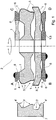
- FIG. 1 an inventive notching tool with a tool body 2 and associated workpiece 7 in four variants A, B, C, D of the invention is shown greatly simplified.
- the variants A, B, C, D shown here are modeled on a tool body 2 for reasons of illustration. All illustrated variants A, B, C, D effect the same machining of the workpiece 7.
- the notching tool is designed as a rotary working tool.
- the tool body 2 is composed of a plurality of basic bodies 1, which are pushed concentrically to each other on a driven shaft and rotate with it, wherein they are preferably releasably connected to the shaft.
- the tool body 2 has, on an outer surface facing the workpiece 7, a first processing region 3 with geometrically indefinite cutting edges 5 and a second processing region 4 with geometrically determined cutting 6.
- the first processing area 3 latches out of the workpiece 7 a first contour area 3 '
- the second processing area latches out of the workpiece 7 a second contour area 4'.
- the second contour region 4 ' is formed in the illustrated case by two outer chamfers.
- All four illustrated variants A, B, C, D show an insert 8, which in each case has at least one geometrically determined cutting edge 6, which forms the second processing region 4 and unlatches the second contour region 4 'from the workpiece 7.
- a plurality of geometrically determined cutting edges 6 are distributed over the circumference of the tool body 2 in the second processing region 4.
- the cutting plate geometrically defined cutting 6 for both directions of rotation, ie with opposite intended cutting directions have.
- Variant A shows a cutting plate 8, which is connected to one of the base body 1, wherein the base body 1, which carries the cutting plate 8, at the same time forms a part of the first processing area 3.
- the cutting plate 8 is preferably designed as an indexable insert, which is detachably mounted on the base body 1.
- a plurality of such cutting plates 8 are arranged at regular intervals over the circumference of the main body 1.
- the cutting plate 8 is preferably mounted directly on the base body 1 via a screw connection or indirectly via a cutting plate carrier.
- the cutting plate 8 is formed by a single annular element that is connected to one of the base body 1 and at least one of its circumference geometrically has certain cutting edge 6, which forms the second processing area 4. Again, the cutting plate 8 is connected to one of the base body 1, which form at least a part of the first processing area 3 on an outer surface facing the workpiece 7.
- Variant C represents a cutting plate 8 which is connected to a base body 1 which is pushed onto the shaft concentrically with respect to the other base bodies 1, is releasably connected to the shaft and rotates with this and the other basic bodies 1.
- the cutting plate 8 is preferably formed in variant C of an annular element.
- the connection between the cutting plate 8 and the base body 1 is preferably carried out as a permanent connection, which in particular includes soldering or welding connections, but also a shrinking of the annular cutting plate 8 on the base body is conceivable.
- the last illustrated variant D shows similar to the variant C, a cutting plate 8, which is executed in variant D, however, in one piece with the base body 1.
- Base body 1 and insert 8 thus form a unit.
Landscapes
- Engineering & Computer Science (AREA)
- Mechanical Engineering (AREA)
- Chemical & Material Sciences (AREA)
- Ceramic Engineering (AREA)
- Inorganic Chemistry (AREA)
- Milling Processes (AREA)
- Food-Manufacturing Devices (AREA)
Claims (8)
- Outil à entailler, en particulier destiné à l'usinage de profilés en plastique ou en aluminium, comprenant un corps d'outil (2) formé par plusieurs corps de base (1) et comportant au moins une première zone d'usinage (3) destinée à entailler un premier contour (3') et au moins une deuxième zone d'usinage (4) destinée à entailler un deuxième contour (4') de façon à ce que la première zone d'usinage (3) comporte des lames (5) à géométrie non définie et à ce que le corps d'outil (2) est formé par plusieurs corps de base (1) arrangés de façon concentriques entre eux et amovibles sur un arbre entraîné et en mouvement de rotation avec celui-ci, caractérisé en ce qu'au moins deux fils coupants (6) à géométrie déterminée sont prévus pour au moins une partie de la deuxième zone d'usinage (4) dont les directions de coupe sont opposées.
- Outil à entailler selon la revendication un, caractérisé en ce que la première zone d'usinage (3) est formée par une surface diamantée extérieure du corps d'outil (2) et orientée vers la pièce à usiner (7).
- Outil à entailler selon une ou plusieurs des revendications précédentes, caractérisé en ce que la deuxième zone d'usinage (4) est formée au moins par une plaquette de coupe (8) de préférence en carbure et possédant au moins un fil coupant (6) à géométrie déterminée.
- Outil à entailler selon une ou plusieurs des revendications précédentes, caractérisé en ce que la première zone d'usinage (3) et la deuxième zone d'usinage (4) sont configurées de façon à ce qu'elles peuvent être adaptées à différents contours souhaités d'une pièce à usiner (7) et ceci en particulier de façon à ce que l'usinage de la pièce à usiner (7) peut être effectué en une seule opération.
- Outil à entailler selon une ou plusieurs des revendications précédentes, caractérisé en ce qu'au moins un des corps de base (1) est formé par une plaquette de coupe (8).
- Outil à entailler selon une ou plusieurs des revendications précédentes, caractérisé en ce que les plaquettes de coupe (8) sont liées à un des corps de base (1) de façon fixe ou amovible.
- Outil à entailler selon une ou plusieurs des revendications précédentes, caractérisé en ce que la plaquette de coupe (8) est une plaquette de coupe indexable, liée à un des corps de base (1) de façon amovible.
- Outil à entailler selon une ou plusieurs des revendications précédentes, caractérisé en ce que la plaquette de coupe (8) est fixée à un des corps de base (1) via un système de serrage et de desserrage de façon mobile coulissant en continu ou par pas ou de manière rotatif par rapport au corps de base (1).
Priority Applications (2)
| Application Number | Priority Date | Filing Date | Title |
|---|---|---|---|
| SI200532221T SI1577060T1 (sl) | 2004-03-19 | 2005-03-18 | Zarezovalno orodje |
| PL05006044T PL1577060T3 (pl) | 2004-03-19 | 2005-03-18 | Narzędzie do obróbki krawędzi profili |
Applications Claiming Priority (2)
| Application Number | Priority Date | Filing Date | Title |
|---|---|---|---|
| DE200420004492 DE202004004492U1 (de) | 2004-03-19 | 2004-03-19 | Ausklinkwerkzeug |
| DE202004004492U | 2004-03-19 |
Publications (3)
| Publication Number | Publication Date |
|---|---|
| EP1577060A2 EP1577060A2 (fr) | 2005-09-21 |
| EP1577060A3 EP1577060A3 (fr) | 2006-04-12 |
| EP1577060B1 true EP1577060B1 (fr) | 2018-05-16 |
Family
ID=34802099
Family Applications (1)
| Application Number | Title | Priority Date | Filing Date |
|---|---|---|---|
| EP05006044.1A Expired - Lifetime EP1577060B1 (fr) | 2004-03-19 | 2005-03-18 | Outil à entailler |
Country Status (4)
| Country | Link |
|---|---|
| EP (1) | EP1577060B1 (fr) |
| DE (1) | DE202004004492U1 (fr) |
| PL (1) | PL1577060T3 (fr) |
| SI (1) | SI1577060T1 (fr) |
Families Citing this family (1)
| Publication number | Priority date | Publication date | Assignee | Title |
|---|---|---|---|---|
| DE202009014144U1 (de) | 2009-10-19 | 2011-03-03 | Mader, Gert | Ausklinkwerkzeug |
Citations (1)
| Publication number | Priority date | Publication date | Assignee | Title |
|---|---|---|---|---|
| DE20218724U1 (de) * | 2002-12-02 | 2003-03-13 | Leistner Werkzeugtechnik, 08328 Stützengrün | Rotatorisch arbeitendes Ausklinkwerkzeug |
Family Cites Families (6)
| Publication number | Priority date | Publication date | Assignee | Title |
|---|---|---|---|---|
| DE2238387A1 (de) * | 1972-08-04 | 1974-03-28 | Winter & Sohn Ernst | Mehrschneidiges zerspanwerkzeug |
| US4171926A (en) * | 1978-04-21 | 1979-10-23 | American Optical Corporation | Lens cutter |
| DE3542258A1 (de) * | 1985-11-29 | 1987-06-04 | Howema Gmbh Wittenborn & Edel | Werkzeug fuer die spanabhebende bearbeitung, vorzugsweise fraes- und schleifwerkzeug |
| DE8629226U1 (de) * | 1986-11-03 | 1986-12-18 | Wernicke & Co GmbH, 40231 Düsseldorf | Drehwerkzeug zur Randbearbeitung von Brillenglasrändern |
| US5626511A (en) * | 1994-10-03 | 1997-05-06 | National Optronics, Inc. | Combination lens edger, polisher, and safety beveler, tool therefor and use thereof |
| DE10255058A1 (de) * | 2002-11-25 | 2004-06-17 | Loh Optikmaschinen Ag | Verfahren und Vorrichtung zur Randbearbeitung einer optischen Linse aus Kunststoff sowie Kombinationswerkzeug dafür |
-
2004
- 2004-03-19 DE DE200420004492 patent/DE202004004492U1/de not_active Expired - Lifetime
-
2005
- 2005-03-18 EP EP05006044.1A patent/EP1577060B1/fr not_active Expired - Lifetime
- 2005-03-18 PL PL05006044T patent/PL1577060T3/pl unknown
- 2005-03-18 SI SI200532221T patent/SI1577060T1/sl unknown
Patent Citations (1)
| Publication number | Priority date | Publication date | Assignee | Title |
|---|---|---|---|---|
| DE20218724U1 (de) * | 2002-12-02 | 2003-03-13 | Leistner Werkzeugtechnik, 08328 Stützengrün | Rotatorisch arbeitendes Ausklinkwerkzeug |
Also Published As
| Publication number | Publication date |
|---|---|
| EP1577060A3 (fr) | 2006-04-12 |
| DE202004004492U1 (de) | 2005-07-21 |
| EP1577060A2 (fr) | 2005-09-21 |
| SI1577060T1 (sl) | 2018-10-30 |
| PL1577060T3 (pl) | 2018-10-31 |
Similar Documents
| Publication | Publication Date | Title |
|---|---|---|
| EP1317985B1 (fr) | Alesoir | |
| EP1598137B1 (fr) | Machine de taillage de roues dentées coniques pour chanfreiner et/ou ébavurer une roue dentée ainsi qu'un procédé correspondant | |
| EP1321210B1 (fr) | Outil de chanfreinage | |
| DE3610016C2 (fr) | ||
| EP2484471B1 (fr) | Outil d'usinage | |
| EP1641585B1 (fr) | Plaquette de coupe | |
| EP1286802B1 (fr) | Fraise trois tailles | |
| DE19743971B4 (de) | Schneideinsatz, Fräswerkzeug und Verwendung des Fräswerkzeuges | |
| DE102005033920A1 (de) | Schneideinsatz, Werkzeug sowie Verfahren zur spanenden Bearbeitung eines Werkstücks | |
| EP1283083B1 (fr) | Plaquette de fraisage | |
| AT398049B (de) | Werkzeugträger zum wirbeln bzw. schälen von aussengewinden, schnecken und profilen | |
| DE102007038935B4 (de) | Stabmesserkopf und entsprechende Werkzeugmaschine | |
| DE102017105032A1 (de) | Werkzeug, Maschine und Verfahren zum Erzeugen von dachfirstartigen Anspitzungen an Zähnen eines innen- und außenverzahnten Zahnrads | |
| DE10112165B4 (de) | Stabmesserkopf zum Verzahnen | |
| DE102005043842B4 (de) | Kugel- oder Torusfräser | |
| DE10333621B4 (de) | Schneideinsatz | |
| EP0841116B1 (fr) | Méthode de travail de surfaces de pièces symétriques en rotation et outil employé | |
| EP1577060B1 (fr) | Outil à entailler | |
| DE19934393B4 (de) | Kombiniertes Werkzeug zur Bearbeitung von rotationssymmetrischen Bohrungen in Werkstücken | |
| DE102004008166A1 (de) | Werkzeug zur spanenden Bearbeitung von Präzisionsbohrungen | |
| EP1281466B1 (fr) | Outil d'usinage par enlèvement de copeaux | |
| DE102017208017B4 (de) | Mehrschneidige Reibahle | |
| DE3909643C2 (de) | Mehrschneidenwerkzeugkopf zur spanabhebenden Vor- und Feinbearbeitung mit kreisförmiger Schnittbewegung | |
| DE10338276B4 (de) | Fräswerkzeug | |
| DE3504296C2 (fr) |
Legal Events
| Date | Code | Title | Description |
|---|---|---|---|
| PUAI | Public reference made under article 153(3) epc to a published international application that has entered the european phase |
Free format text: ORIGINAL CODE: 0009012 |
|
| AK | Designated contracting states |
Kind code of ref document: A2 Designated state(s): AT BE BG CH CY CZ DE DK EE ES FI FR GB GR HU IE IS IT LI LT LU MC NL PL PT RO SE SI SK TR |
|
| AX | Request for extension of the european patent |
Extension state: AL BA HR LV MK YU |
|
| PUAL | Search report despatched |
Free format text: ORIGINAL CODE: 0009013 |
|
| AK | Designated contracting states |
Kind code of ref document: A3 Designated state(s): AT BE BG CH CY CZ DE DK EE ES FI FR GB GR HU IE IS IT LI LT LU MC NL PL PT RO SE SI SK TR |
|
| AX | Request for extension of the european patent |
Extension state: AL BA HR LV MK YU |
|
| RIC1 | Information provided on ipc code assigned before grant |
Ipc: B24B 9/14 20060101ALI20060222BHEP Ipc: B24D 7/18 20060101AFI20050617BHEP Ipc: B23C 3/12 20060101ALI20060222BHEP |
|
| 17P | Request for examination filed |
Effective date: 20060926 |
|
| AKX | Designation fees paid |
Designated state(s): AT BE BG CH CY CZ DE DK EE ES FI FR GB GR HU IE IS IT LI LT LU MC NL PL PT RO SE SI SK TR |
|
| AXX | Extension fees paid |
Extension state: BA Payment date: 20060926 Extension state: LV Payment date: 20060926 Extension state: AL Payment date: 20060926 Extension state: MK Payment date: 20060926 Extension state: HR Payment date: 20060926 Extension state: YU Payment date: 20060926 |
|
| 17Q | First examination report despatched |
Effective date: 20141002 |
|
| STAA | Information on the status of an ep patent application or granted ep patent |
Free format text: STATUS: EXAMINATION IS IN PROGRESS |
|
| REG | Reference to a national code |
Ref country code: DE Ref legal event code: R079 Ref document number: 502005015825 Country of ref document: DE Free format text: PREVIOUS MAIN CLASS: B24D0007180000 Ipc: B23C0005080000 |
|
| GRAP | Despatch of communication of intention to grant a patent |
Free format text: ORIGINAL CODE: EPIDOSNIGR1 |
|
| STAA | Information on the status of an ep patent application or granted ep patent |
Free format text: STATUS: GRANT OF PATENT IS INTENDED |
|
| RIC1 | Information provided on ipc code assigned before grant |
Ipc: B23C 5/08 20060101AFI20170824BHEP Ipc: B24B 9/14 20060101ALI20170824BHEP Ipc: B23C 3/12 20060101ALI20170824BHEP Ipc: B24D 7/18 20060101ALI20170824BHEP |
|
| INTG | Intention to grant announced |
Effective date: 20170913 |
|
| GRAJ | Information related to disapproval of communication of intention to grant by the applicant or resumption of examination proceedings by the epo deleted |
Free format text: ORIGINAL CODE: EPIDOSDIGR1 |
|
| STAA | Information on the status of an ep patent application or granted ep patent |
Free format text: STATUS: EXAMINATION IS IN PROGRESS |
|
| GRAS | Grant fee paid |
Free format text: ORIGINAL CODE: EPIDOSNIGR3 |
|
| STAA | Information on the status of an ep patent application or granted ep patent |
Free format text: STATUS: GRANT OF PATENT IS INTENDED |
|
| GRAP | Despatch of communication of intention to grant a patent |
Free format text: ORIGINAL CODE: EPIDOSNIGR1 |
|
| INTC | Intention to grant announced (deleted) | ||
| INTG | Intention to grant announced |
Effective date: 20180129 |
|
| GRAA | (expected) grant |
Free format text: ORIGINAL CODE: 0009210 |
|
| STAA | Information on the status of an ep patent application or granted ep patent |
Free format text: STATUS: THE PATENT HAS BEEN GRANTED |
|
| AK | Designated contracting states |
Kind code of ref document: B1 Designated state(s): AT BE BG CH CY CZ DE DK EE ES FI FR GB GR HU IE IS IT LI LT LU MC NL PL PT RO SE SI SK TR |
|
| AX | Request for extension of the european patent |
Extension state: AL BA HR LV MK YU |
|
| REG | Reference to a national code |
Ref country code: GB Ref legal event code: FG4D Free format text: NOT ENGLISH |
|
| REG | Reference to a national code |
Ref country code: CH Ref legal event code: EP |
|
| REG | Reference to a national code |
Ref country code: DE Ref legal event code: R096 Ref document number: 502005015825 Country of ref document: DE |
|
| REG | Reference to a national code |
Ref country code: IE Ref legal event code: FG4D Free format text: LANGUAGE OF EP DOCUMENT: GERMAN |
|
| REG | Reference to a national code |
Ref country code: AT Ref legal event code: REF Ref document number: 999082 Country of ref document: AT Kind code of ref document: T Effective date: 20180615 |
|
| REG | Reference to a national code |
Ref country code: NL Ref legal event code: FP |
|
| REG | Reference to a national code |
Ref country code: LT Ref legal event code: MG4D |
|
| PG25 | Lapsed in a contracting state [announced via postgrant information from national office to epo] |
Ref country code: ES Free format text: LAPSE BECAUSE OF FAILURE TO SUBMIT A TRANSLATION OF THE DESCRIPTION OR TO PAY THE FEE WITHIN THE PRESCRIBED TIME-LIMIT Effective date: 20180516 Ref country code: LT Free format text: LAPSE BECAUSE OF FAILURE TO SUBMIT A TRANSLATION OF THE DESCRIPTION OR TO PAY THE FEE WITHIN THE PRESCRIBED TIME-LIMIT Effective date: 20180516 Ref country code: SE Free format text: LAPSE BECAUSE OF FAILURE TO SUBMIT A TRANSLATION OF THE DESCRIPTION OR TO PAY THE FEE WITHIN THE PRESCRIBED TIME-LIMIT Effective date: 20180516 Ref country code: BG Free format text: LAPSE BECAUSE OF FAILURE TO SUBMIT A TRANSLATION OF THE DESCRIPTION OR TO PAY THE FEE WITHIN THE PRESCRIBED TIME-LIMIT Effective date: 20180816 Ref country code: FI Free format text: LAPSE BECAUSE OF FAILURE TO SUBMIT A TRANSLATION OF THE DESCRIPTION OR TO PAY THE FEE WITHIN THE PRESCRIBED TIME-LIMIT Effective date: 20180516 |
|
| PG25 | Lapsed in a contracting state [announced via postgrant information from national office to epo] |
Ref country code: GR Free format text: LAPSE BECAUSE OF FAILURE TO SUBMIT A TRANSLATION OF THE DESCRIPTION OR TO PAY THE FEE WITHIN THE PRESCRIBED TIME-LIMIT Effective date: 20180817 |
|
| PG25 | Lapsed in a contracting state [announced via postgrant information from national office to epo] |
Ref country code: PT Free format text: LAPSE BECAUSE OF FAILURE TO SUBMIT A TRANSLATION OF THE DESCRIPTION OR TO PAY THE FEE WITHIN THE PRESCRIBED TIME-LIMIT Effective date: 20180917 |
|
| PG25 | Lapsed in a contracting state [announced via postgrant information from national office to epo] |
Ref country code: DK Free format text: LAPSE BECAUSE OF FAILURE TO SUBMIT A TRANSLATION OF THE DESCRIPTION OR TO PAY THE FEE WITHIN THE PRESCRIBED TIME-LIMIT Effective date: 20180516 Ref country code: SK Free format text: LAPSE BECAUSE OF FAILURE TO SUBMIT A TRANSLATION OF THE DESCRIPTION OR TO PAY THE FEE WITHIN THE PRESCRIBED TIME-LIMIT Effective date: 20180516 Ref country code: CZ Free format text: LAPSE BECAUSE OF FAILURE TO SUBMIT A TRANSLATION OF THE DESCRIPTION OR TO PAY THE FEE WITHIN THE PRESCRIBED TIME-LIMIT Effective date: 20180516 Ref country code: RO Free format text: LAPSE BECAUSE OF FAILURE TO SUBMIT A TRANSLATION OF THE DESCRIPTION OR TO PAY THE FEE WITHIN THE PRESCRIBED TIME-LIMIT Effective date: 20180516 Ref country code: EE Free format text: LAPSE BECAUSE OF FAILURE TO SUBMIT A TRANSLATION OF THE DESCRIPTION OR TO PAY THE FEE WITHIN THE PRESCRIBED TIME-LIMIT Effective date: 20180516 |
|
| REG | Reference to a national code |
Ref country code: CH Ref legal event code: PK Free format text: BERICHTIGUNGEN |
|
| RIC2 | Information provided on ipc code assigned after grant |
Ipc: B23C 5/08 20060101AFI20170824BHEP Ipc: B23C 3/12 20060101ALI20170824BHEP Ipc: B24D 7/18 20060101ALI20170824BHEP Ipc: B24B 9/14 20060101ALI20170824BHEP |
|
| REG | Reference to a national code |
Ref country code: DE Ref legal event code: R097 Ref document number: 502005015825 Country of ref document: DE |
|
| PG25 | Lapsed in a contracting state [announced via postgrant information from national office to epo] |
Ref country code: IT Free format text: LAPSE BECAUSE OF FAILURE TO SUBMIT A TRANSLATION OF THE DESCRIPTION OR TO PAY THE FEE WITHIN THE PRESCRIBED TIME-LIMIT Effective date: 20180516 |
|
| PLBE | No opposition filed within time limit |
Free format text: ORIGINAL CODE: 0009261 |
|
| STAA | Information on the status of an ep patent application or granted ep patent |
Free format text: STATUS: NO OPPOSITION FILED WITHIN TIME LIMIT |
|
| 26N | No opposition filed |
Effective date: 20190219 |
|
| REG | Reference to a national code |
Ref country code: DE Ref legal event code: R082 Ref document number: 502005015825 Country of ref document: DE Representative=s name: PATENTANWAELTE OLBRICHT, BUCHHOLD, KEULERTZ PA, DE |
|
| PG25 | Lapsed in a contracting state [announced via postgrant information from national office to epo] |
Ref country code: MC Free format text: LAPSE BECAUSE OF FAILURE TO SUBMIT A TRANSLATION OF THE DESCRIPTION OR TO PAY THE FEE WITHIN THE PRESCRIBED TIME-LIMIT Effective date: 20180516 |
|
| REG | Reference to a national code |
Ref country code: CH Ref legal event code: PL |
|
| GBPC | Gb: european patent ceased through non-payment of renewal fee |
Effective date: 20190318 |
|
| PG25 | Lapsed in a contracting state [announced via postgrant information from national office to epo] |
Ref country code: LU Free format text: LAPSE BECAUSE OF NON-PAYMENT OF DUE FEES Effective date: 20190318 |
|
| PG25 | Lapsed in a contracting state [announced via postgrant information from national office to epo] |
Ref country code: GB Free format text: LAPSE BECAUSE OF NON-PAYMENT OF DUE FEES Effective date: 20190318 Ref country code: LI Free format text: LAPSE BECAUSE OF NON-PAYMENT OF DUE FEES Effective date: 20190331 Ref country code: CH Free format text: LAPSE BECAUSE OF NON-PAYMENT OF DUE FEES Effective date: 20190331 Ref country code: IE Free format text: LAPSE BECAUSE OF NON-PAYMENT OF DUE FEES Effective date: 20190318 |
|
| PG25 | Lapsed in a contracting state [announced via postgrant information from national office to epo] |
Ref country code: FR Free format text: LAPSE BECAUSE OF NON-PAYMENT OF DUE FEES Effective date: 20190331 |
|
| PG25 | Lapsed in a contracting state [announced via postgrant information from national office to epo] |
Ref country code: TR Free format text: LAPSE BECAUSE OF FAILURE TO SUBMIT A TRANSLATION OF THE DESCRIPTION OR TO PAY THE FEE WITHIN THE PRESCRIBED TIME-LIMIT Effective date: 20180516 |
|
| REG | Reference to a national code |
Ref country code: AT Ref legal event code: MM01 Ref document number: 999082 Country of ref document: AT Kind code of ref document: T Effective date: 20190318 |
|
| PG25 | Lapsed in a contracting state [announced via postgrant information from national office to epo] |
Ref country code: AT Free format text: LAPSE BECAUSE OF NON-PAYMENT OF DUE FEES Effective date: 20190318 |
|
| PG25 | Lapsed in a contracting state [announced via postgrant information from national office to epo] |
Ref country code: CY Free format text: LAPSE BECAUSE OF FAILURE TO SUBMIT A TRANSLATION OF THE DESCRIPTION OR TO PAY THE FEE WITHIN THE PRESCRIBED TIME-LIMIT Effective date: 20180516 |
|
| PG25 | Lapsed in a contracting state [announced via postgrant information from national office to epo] |
Ref country code: IS Free format text: LAPSE BECAUSE OF FAILURE TO SUBMIT A TRANSLATION OF THE DESCRIPTION OR TO PAY THE FEE WITHIN THE PRESCRIBED TIME-LIMIT Effective date: 20180916 |
|
| PG25 | Lapsed in a contracting state [announced via postgrant information from national office to epo] |
Ref country code: HU Free format text: LAPSE BECAUSE OF FAILURE TO SUBMIT A TRANSLATION OF THE DESCRIPTION OR TO PAY THE FEE WITHIN THE PRESCRIBED TIME-LIMIT; INVALID AB INITIO Effective date: 20050318 |
|
| REG | Reference to a national code |
Ref country code: DE Ref legal event code: R082 Ref document number: 502005015825 Country of ref document: DE Representative=s name: PATENTANWAELTE OLBRICHT, BUCHHOLD, KEULERTZ PA, DE |
|
| PGFP | Annual fee paid to national office [announced via postgrant information from national office to epo] |
Ref country code: SI Payment date: 20230316 Year of fee payment: 19 Ref country code: PL Payment date: 20230316 Year of fee payment: 19 Ref country code: BE Payment date: 20230321 Year of fee payment: 19 |
|
| PGFP | Annual fee paid to national office [announced via postgrant information from national office to epo] |
Ref country code: NL Payment date: 20230321 Year of fee payment: 19 |
|
| PGFP | Annual fee paid to national office [announced via postgrant information from national office to epo] |
Ref country code: DE Payment date: 20240331 Year of fee payment: 20 |
|
| REG | Reference to a national code |
Ref country code: NL Ref legal event code: MM Effective date: 20240401 |
|
| PG25 | Lapsed in a contracting state [announced via postgrant information from national office to epo] |
Ref country code: NL Free format text: LAPSE BECAUSE OF NON-PAYMENT OF DUE FEES Effective date: 20240401 |
|
| REG | Reference to a national code |
Ref country code: BE Ref legal event code: MM Effective date: 20240331 |
|
| PG25 | Lapsed in a contracting state [announced via postgrant information from national office to epo] |
Ref country code: NL Free format text: LAPSE BECAUSE OF NON-PAYMENT OF DUE FEES Effective date: 20240401 |
|
| PG25 | Lapsed in a contracting state [announced via postgrant information from national office to epo] |
Ref country code: BE Free format text: LAPSE BECAUSE OF NON-PAYMENT OF DUE FEES Effective date: 20240331 |
|
| PG25 | Lapsed in a contracting state [announced via postgrant information from national office to epo] |
Ref country code: BE Free format text: LAPSE BECAUSE OF NON-PAYMENT OF DUE FEES Effective date: 20240331 |
|
| REG | Reference to a national code |
Ref country code: DE Ref legal event code: R071 Ref document number: 502005015825 Country of ref document: DE |
|
| PG25 | Lapsed in a contracting state [announced via postgrant information from national office to epo] |
Ref country code: PL Free format text: LAPSE BECAUSE OF NON-PAYMENT OF DUE FEES Effective date: 20240318 |
|
| REG | Reference to a national code |
Ref country code: SI Ref legal event code: KO00 Effective date: 20240319 |