EP1577075A2 - Dispositif pour la production de tubes plastiques - Google Patents
Dispositif pour la production de tubes plastiques Download PDFInfo
- Publication number
- EP1577075A2 EP1577075A2 EP05007210A EP05007210A EP1577075A2 EP 1577075 A2 EP1577075 A2 EP 1577075A2 EP 05007210 A EP05007210 A EP 05007210A EP 05007210 A EP05007210 A EP 05007210A EP 1577075 A2 EP1577075 A2 EP 1577075A2
- Authority
- EP
- European Patent Office
- Prior art keywords
- channel
- distribution
- channel sections
- radial
- branch
- Prior art date
- Legal status (The legal status is an assumption and is not a legal conclusion. Google has not performed a legal analysis and makes no representation as to the accuracy of the status listed.)
- Granted
Links
- 239000004033 plastic Substances 0.000 title claims abstract description 40
- 229920003023 plastic Polymers 0.000 title claims abstract description 40
- 238000009826 distribution Methods 0.000 claims abstract description 135
- 238000004519 manufacturing process Methods 0.000 claims abstract description 23
- 239000007921 spray Substances 0.000 claims abstract description 22
- 238000001125 extrusion Methods 0.000 claims abstract 3
- 230000015572 biosynthetic process Effects 0.000 claims description 5
- 230000000295 complement effect Effects 0.000 claims description 3
- 230000005611 electricity Effects 0.000 claims description 3
- 230000000284 resting effect Effects 0.000 claims description 3
- 239000002826 coolant Substances 0.000 claims description 2
- 230000001617 migratory effect Effects 0.000 claims description 2
- 238000004904 shortening Methods 0.000 claims description 2
- 230000002093 peripheral effect Effects 0.000 description 8
- 239000000155 melt Substances 0.000 description 6
- 239000000203 mixture Substances 0.000 description 4
- 230000000694 effects Effects 0.000 description 3
- 230000007423 decrease Effects 0.000 description 2
- 125000006850 spacer group Chemical group 0.000 description 2
- 239000013598 vector Substances 0.000 description 2
- 238000010276 construction Methods 0.000 description 1
- 238000001816 cooling Methods 0.000 description 1
- 238000011161 development Methods 0.000 description 1
- 230000018109 developmental process Effects 0.000 description 1
- 238000005516 engineering process Methods 0.000 description 1
- 230000002349 favourable effect Effects 0.000 description 1
- 239000000463 material Substances 0.000 description 1
- 239000002356 single layer Substances 0.000 description 1
- XLYOFNOQVPJJNP-UHFFFAOYSA-N water Substances O XLYOFNOQVPJJNP-UHFFFAOYSA-N 0.000 description 1
- 238000003466 welding Methods 0.000 description 1
Images


Classifications
-
- B—PERFORMING OPERATIONS; TRANSPORTING
- B29—WORKING OF PLASTICS; WORKING OF SUBSTANCES IN A PLASTIC STATE IN GENERAL
- B29C—SHAPING OR JOINING OF PLASTICS; SHAPING OF MATERIAL IN A PLASTIC STATE, NOT OTHERWISE PROVIDED FOR; AFTER-TREATMENT OF THE SHAPED PRODUCTS, e.g. REPAIRING
- B29C48/00—Extrusion moulding, i.e. expressing the moulding material through a die or nozzle which imparts the desired form; Apparatus therefor
- B29C48/25—Component parts, details or accessories; Auxiliary operations
- B29C48/36—Means for plasticising or homogenising the moulding material or forcing it through the nozzle or die
- B29C48/50—Details of extruders
- B29C48/695—Flow dividers, e.g. breaker plates
- B29C48/70—Flow dividers, e.g. breaker plates comprising means for dividing, distributing and recombining melt flows
- B29C48/705—Flow dividers, e.g. breaker plates comprising means for dividing, distributing and recombining melt flows in the die zone, e.g. to create flow homogeneity
-
- B—PERFORMING OPERATIONS; TRANSPORTING
- B29—WORKING OF PLASTICS; WORKING OF SUBSTANCES IN A PLASTIC STATE IN GENERAL
- B29C—SHAPING OR JOINING OF PLASTICS; SHAPING OF MATERIAL IN A PLASTIC STATE, NOT OTHERWISE PROVIDED FOR; AFTER-TREATMENT OF THE SHAPED PRODUCTS, e.g. REPAIRING
- B29C48/00—Extrusion moulding, i.e. expressing the moulding material through a die or nozzle which imparts the desired form; Apparatus therefor
- B29C48/001—Combinations of extrusion moulding with other shaping operations
- B29C48/0013—Extrusion moulding in several steps, i.e. components merging outside the die
- B29C48/0015—Extrusion moulding in several steps, i.e. components merging outside the die producing hollow articles having components brought in contact outside the extrusion die
-
- B—PERFORMING OPERATIONS; TRANSPORTING
- B29—WORKING OF PLASTICS; WORKING OF SUBSTANCES IN A PLASTIC STATE IN GENERAL
- B29C—SHAPING OR JOINING OF PLASTICS; SHAPING OF MATERIAL IN A PLASTIC STATE, NOT OTHERWISE PROVIDED FOR; AFTER-TREATMENT OF THE SHAPED PRODUCTS, e.g. REPAIRING
- B29C48/00—Extrusion moulding, i.e. expressing the moulding material through a die or nozzle which imparts the desired form; Apparatus therefor
- B29C48/03—Extrusion moulding, i.e. expressing the moulding material through a die or nozzle which imparts the desired form; Apparatus therefor characterised by the shape of the extruded material at extrusion
- B29C48/09—Articles with cross-sections having partially or fully enclosed cavities, e.g. pipes or channels
-
- B—PERFORMING OPERATIONS; TRANSPORTING
- B29—WORKING OF PLASTICS; WORKING OF SUBSTANCES IN A PLASTIC STATE IN GENERAL
- B29C—SHAPING OR JOINING OF PLASTICS; SHAPING OF MATERIAL IN A PLASTIC STATE, NOT OTHERWISE PROVIDED FOR; AFTER-TREATMENT OF THE SHAPED PRODUCTS, e.g. REPAIRING
- B29C48/00—Extrusion moulding, i.e. expressing the moulding material through a die or nozzle which imparts the desired form; Apparatus therefor
- B29C48/16—Articles comprising two or more components, e.g. co-extruded layers
- B29C48/18—Articles comprising two or more components, e.g. co-extruded layers the components being layers
- B29C48/21—Articles comprising two or more components, e.g. co-extruded layers the components being layers the layers being joined at their surfaces
-
- B—PERFORMING OPERATIONS; TRANSPORTING
- B29—WORKING OF PLASTICS; WORKING OF SUBSTANCES IN A PLASTIC STATE IN GENERAL
- B29C—SHAPING OR JOINING OF PLASTICS; SHAPING OF MATERIAL IN A PLASTIC STATE, NOT OTHERWISE PROVIDED FOR; AFTER-TREATMENT OF THE SHAPED PRODUCTS, e.g. REPAIRING
- B29C48/00—Extrusion moulding, i.e. expressing the moulding material through a die or nozzle which imparts the desired form; Apparatus therefor
- B29C48/25—Component parts, details or accessories; Auxiliary operations
- B29C48/30—Extrusion nozzles or dies
- B29C48/303—Extrusion nozzles or dies using dies or die parts movable in a closed circuit, e.g. mounted on movable endless support
-
- B—PERFORMING OPERATIONS; TRANSPORTING
- B29—WORKING OF PLASTICS; WORKING OF SUBSTANCES IN A PLASTIC STATE IN GENERAL
- B29C—SHAPING OR JOINING OF PLASTICS; SHAPING OF MATERIAL IN A PLASTIC STATE, NOT OTHERWISE PROVIDED FOR; AFTER-TREATMENT OF THE SHAPED PRODUCTS, e.g. REPAIRING
- B29C49/00—Blow-moulding, i.e. blowing a preform or parison to a desired shape within a mould; Apparatus therefor
- B29C49/0015—Making articles of indefinite length, e.g. corrugated tubes
- B29C49/0021—Making articles of indefinite length, e.g. corrugated tubes using moulds or mould parts movable in a closed path, e.g. mounted on movable endless supports
Definitions
- the invention relates to a device for producing seamless Plastic pipes according to the preamble of claim 1.
- Such devices with a spray head with a distributor with perpendicular to the axis of the mold cavity extending distribution channels have the Advantage that the spray head on the one hand with a short overall length and on the other hand can be formed with a small diameter, so that the Distributor, preferably formed as a plate, within the cross section the mold cavity can be arranged. Due to the low Spray head length, the supply channel for the melt over a large part its length be formed with a relatively large diameter, so that with comparatively low pressures can be worked, but still sufficient melt the annular gap or in the production direction is fed in succession annular gaps.
- Such a spray head is known from DE 198 35 189 A1.
- the distribution channels This so-called Plattenspritzkopfs are branched like a family tree Channels formed. To form these channels are in a distribution plate formed corresponding grooves which are covered by a cover plate. Disadvantage of the family tree branched distribution channels is that the Variability of the number of distribution channels or the variability of the Branching degree of the distribution channels on stages forming powers of 2, is limited and therefore a continuous variation is not possible.
- Another fundamental constructive limitation results from the fact that the distribution channels be formed according to the concept of DE 198 35 189 each exactly the same length in order to ensure equal flow paths, eventually to a homogeneous Composition of emerging at the annular gap plastic strand guarantee.
- the disk spray head has a distribution plate in the essentially radially arranged radial grooves, which have a Cover plate covered star-shaped radial distribution channels form.
- the Plastic melt is transferred to the center axis of the mold cavity via one fed concentric annular gap of this distribution plate.
- the melt on the outer circumference of the distribution plate arranged annular gap supplied with integrated spiral distributor.
- a spray head is known, although not as a disk head is formed, but already perpendicular to the central axis extending distribution channels having.
- the distribution channels are directed radially with arcuate End sections, in the manner of a helical distributor in the outer annular gap open out.
- the variability of the degree of distribution is on the one hand by the radial Alignment of the channels and on the other hand by the design of it limited subsequent spiral distributor.
- An essential limitation results also from the fact that according to the concept of US 3,809,515 the flow paths in the Distribution channels must be exactly the same length to a homogeneous To ensure flow rate.
- the invention is based on the object, a device of the above so-called type so that a homogeneous as possible Composition of the exiting at the annular gap of the spray head Plastic melt jet is obtained.
- the solution provides a plurality of distribution channels, each in at least one branch point with the formation of two each Branching branch channel sections.
- the arrangement of the distribution channels is star-shaped from the central inlet opening in the distributor. Essential in that the radially outgoing from the inlet opening first channel sections the distribution channels are each straight and this straight radial first channel sections each have a branch point at their end, in which they branch into at least two branch channel sections. The Arrangement is so far symmetrically star-shaped starting from the Inlet opening. If necessary, the distribution channels go after repeated ones Branching finally in arcuate, preferably circular arc-shaped End sections over, the plastic melt in the manner of a spiral distributor Feed annular gap.
- the channel sections are preferably as straight channel sections formed and symmetrical to the axis of the radial arranged first channel section.
- the middle one is three Branch channel sections in a straight line aligned with the radial first Channel section arranged. Due to the straight training of the Channel sections and the branch in a plurality of Branch channel sections results in a high degree of distribution. this applies especially for embodiments in which all of the inlet opening Outgoing distribution channels are designed in this same way and insofar as a symmetry, preferably star structure, is present.
- the distribution device has a distribution plate in which the radial first channel sections as preferably parallel to the plane of the plate extending bores are formed.
- the branch channel sections can be formed as running parallel to the plane of the plate holes. This means that the distribution channels in these sections each by parallel to Plate level extending bores are formed.
- the Holes may also be formed as grooves, which by one or more Overlying cover plates are formed to corresponding channels.
- the distribution device may have a first Distribution plate and have a further distribution plate, wherein in this further Distribution plate sections of the distribution channels, preferably the arcuate channel sections are arranged.
- This further distribution plate can in structurally particularly simple designs as an annular distribution plate be educated.
- the inlet opening and the radial first Channel sections and preferably also the branch channel sections can in one central distribution plate arranged by the annular distribution plate is arranged surrounded.
- a particularly compact arrangement results when the central distribution plate and / or the annular distribution plate a concentric Gradation and have and the two plates complementary are arranged one above the other in terms of gradation.
- the outer annular step edge of the central plate may be the outside overlap annular annular distribution plate and rest on this.
- the arcuate channel sections may be in the outer annular distribution disc arcuate grooves to be formed by the annular step edge of the central plate are covered, so that the arcuate channel sections are formed.
- Particularly compact versions with spray heads with several in Production direction one behind the other arranged distribution devices is in the obtained central arrangement of the inlet opening in the distributor, when the Distributor obtained when the distributor off-center a passage for a supply channel for plastic melt one in the production direction Having downstream distribution device.
- the Distributor also off-center a passage for Supply facilities, e.g. Line for air, electricity, coolant, etc. have.
- each flow path of the inlet opening in the distributor up to the mouth of the distribution channels in extends the annular gap.
- a branched channel results in one of the number of Branch channels corresponding number n of flow paths.
- the flow resistance in the flow through the individual flow paths distribution channels i. of the Flow resistance of the successively flowed through the channel sections of respective distribution channels at different flow paths accordingly is designed differently.
- the inner diameter of the The various flow paths through channel sections depending on the Length of the respective flow path are designed differently.
- Each distribution channel may have one or more branch points, from each run two or more branch channels.
- the Distribution channels in terms of their degree of branching and in terms of the length of the Channel sections are formed differently and the individual flow paths from the inlet to the mouth in the annular gap can have different length.
- the individual channel sections can be any Curve shape, but are preferably for manufacturing reasons as straight Channel sections formed.
- the end portions of the Distribution channels before their confluence in the annular gap in arcuate preferably pass over arcuate channel sections, in the manner of a Spiral distributor can be arranged and the plastic melt in the Initiate annular gap.
- the inlet opening into the manifold is coaxial to the axis of the mold cavity or to the axis of the preferably annular annular gap.
- the inlet opening in the distribution device can However, also be arranged off-center and there may be several Inlets, preferably in a common plane in the Distributor be arranged.
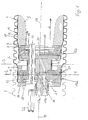
- Fig. 1 is schematically at 1, the corresponding corrugated inner wall of a Corrugator mold baking shown, wherein in the production direction 2 of the corrugated pipe several corresponding mold jaws follow each other directly.
- the Contact surface of two mold jaws is indicated by the line 3 in Fig. 1.
- the production of the multi-walled corrugated pipe is carried out in a conventional manner such that a first, from an annular gap 4 exiting, tubular stream. 5 of plastic melt by suitable means, e.g. in the room 6 applied overpressure, against the inner wall 1 of the corresponding, in Production direction 2 uniformly moving mold baking is created.
- suitable means e.g. in the room 6 applied overpressure
- This Plastic melt tube is replaced by a mandrel 9, the exact training depending on the plastic used and the special pipe shape etc. and therefore is not explained in detail, against the regions 10 of the outer wall eleventh pressed to the forming corrugated tube, wherein the temperature during the An discloses the inner tube 8 of the corrugated tube against the outer wall 11 so is selected that in the areas 10 a welding of outer wall 11th and inner wall 12 takes place and so a corresponding corrugated pipe with ribbed Outside wall 11 and smooth inner wall 12 is formed.
- the formation of the Corrugated pipe itself corresponds to the sketched in Fig. 1 device completely the State of the art.
- Fig. 1 it can be seen that for this purpose, two total of 13a and 13b designated distribution device are provided. These two distribution devices are basically the same. However, the diameter of the Ring slot 4 for the outer wall 11 in the illustrated embodiment something larger than the diameter of the annular slot 7 for the inner wall 12 and Corresponding are also the diameters of the distributing devices 13a and 13b something different. This is necessary in order to prevent the already on the inner wall 1 of the mold jaws adjacent outer wall 11 of the Plastic corrugated pipe with the distributor 13b comes into contact.
- Each of the distributors 13a and 13b comprises two plate-shaped, in outer plan each circular elements, namely a disc-shaped first plate 15 serving as portions of distribution channels 14 within the Plate 15 has bores formed parallel to the plate plane, and a in plan view annular second plate 16, the groove-shaped recesses has, which rest on the in the region of the groove-shaped recesses disc-shaped plate 15 are covered and thus to the in the plate 15th connect trained holes and so the distribution channels 14th to complete.
- the circular in plan outline peripheral surface 24 of the first plate 15 is at a small distance and forming an annular gap 25 of a Outer ring 26 surrounded, the cross section of Fig. 1 can be seen.
- the two distribution devices 13a, 13b are thus from the plate or annular elements 15, 16, 26 assembled and each have Overall, a flat basically plate-shaped configuration.
- the feeding of the plastic melt from the extruder to the distribution devices 13a, 13b takes place via essentially in the production direction 2 extending Feed channels 17a, 17b, in the central axis 18 of the Korrugatorformbacken formed mold cavity run and comparatively can have large cross-section.
- These supply channels 17a, 17b end each in an inlet opening 20 of the corresponding distributor 13a, 13b, from then the distribution channels (see Fig. 2) go out.
- the second supply channel 17b passes through the first Distributor 13a off-center in the form of a plate 15 formed in the Bore 21.
- the bore 21 passes through the plate 15 off-center with distance Inlet opening 20, however, is arranged in the central region of the plate 15 is not covered by the annular plate 16.
- the bore 21 is thus in the cross-sectional area of the central recess of this annular plate 16 arranged. Therefore, the training of a separate aligned is unnecessary Bore in this annular plate 16th
- Feed channel 17b extends in the spacer block 19 which is between the Distributor 13a and downstream in the production direction Distributor 13b is arranged.
- the feed channel 17b points in its course through the spacer block 19 a to the central axis obliquely directed portion and finally opens into an arranged in the central axis 18 end portion into the central inlet 20 of the distributor 13b.
- the passage 22 is in the appropriate position as the Bore 21 off-center with distance to the inlet opening 20 in the distribution plate 15th and arranged in alignment in each distribution device 13a, 13b, so that the Supply lines parallel offset offset to the central center axis 18 Weden can.
- the passage 22 is in each case in a bore in the plate 15 at a distance arranged to the inlet opening 20. She passes through the plate 15 in a Center near area, so that the passage 22 each in the cross-sectional area the central recess of the annular plate 16 is arranged and a separate bore in the annular plate 16 is unnecessary.
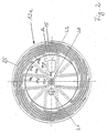
- Fig. 2 is an example of how the distribution channels 14 in the distribution device 13a can be arranged, shown schematically.
- the distribution channels 14 are in the distribution device 13a in a basically arranged star-shaped configuration. All distribution channels 14 have theirs Originating in the central opening 20 and extending in a direction perpendicular to Central axis 18 lying plane A to the periphery of the distribution device 13a out to finally einunden in the annular gap 25.
- the annular gap 25 is between the Peripheral surface 24 of the plate 15 and the radial inner side of the outer ring 26th formed and passes directly into the subsequent nozzle, at the Outlet end of the annular gap 4 is formed.
- Each distribution channel 14 consists of a first radially directed straight Channel section 14r extending from the inlet opening 20 to a Branch point 14v extends.
- Branching point 14v branches the radial channel section 14r into three also straight branch channel sections 14z, which then each pass into arcuate channel sections 14k, the art arranged in the plane
- a distributor helix arranged side by side are and in each case on the peripheral surface 24 of the plate 15 terminate by being there in open the annular gap 25.
- each radial channel section 14r intended. They are arranged crosswise to each other, with adjacent ones Channel sections 14r are each arranged at an angle of 90 °.
- the Branching points 14v are all on one to the inlet opening 20th concentric circle. This means that the radial channel sections 14r each are the same length.
- each radial channel section 14r goes in the Branch point 14v in each case three straight branch channel sections 14z over. she each end on a concentric to the inlet 20 circular line by go there in the arcuate channel sections 14 K.
- the middle Branch passage section 14z radially directed in alignment with the radial Channel section 14r.
- the two outer channel sections 14z run on both sides of the central branch channel portion 14z each at an angle of 45 ° directed to this.
- the middle branch passage portion 14z is shorter than each of them two outer branch channel sections 14z.
- the relative diameters are so chosen that the different length and the associated different flow path of the branch channel sections 14z is compensated and thus from each branch channel section into the arcuate channel sections 14k in each case the same volume flow is supplied. Additionally or alternatively to This compensation via appropriate choice of diameter can be at modified embodiments, a corresponding different Constriction or extension in the branch channel sections 14z to Compensation of the different lengths of the channel sections may be provided.
- the branch channel sections 14z are not formed identically rectilinear or preferably, that the two outer branch channel sections 14z rectilinear, but the middle Branch channel section 14z is formed odd-lined. Furthermore, the Compensation and the arcuate channel sections 14k corresponding Constrictions or extensions or with different Extensions or shortenings may be formed.
- the diameter of all Radial channel sections 14r each identical and over the entire length of the Channel section 14r towards constant.
- the rectilinear adjoining middle of the two channel sections 14z each have the same diameter as the Channel portion 14r, wherein the diameter of this branch channel portion 14z is also constant over the entire length.
- the diameter of the two lateral longer channel sections 14z is each larger than the diameter the middle channel section 14z and also over the entire length of the lateral branch channel sections 14z constant.
- the to the branch channel sections 14z subsequent arcuate channel sections 14k are interconnected identically formed. Their non-circular cross-sectional area corresponds in terms of Area of the cross-sectional area of the side branch passage portions 14z.
- the area of the cross-sectional area of these arcuate channel sections 14k takes, as can be seen from Fig. 1, to the confluence in the annular gap 25 out from.
- the Diameter of the radial channel sections and / or the diameter of Branch channel sections 14z over the length of the respective channel section to Annular gap 25 decreases. The decrease can be continuous over the length of the be formed respective channel sections.
- the arcuate channel sections 14k formed by that in the annular Plate 16 on the support surface with the plate 15 side facing arcuate grooves are formed and these grooves by in this Area resting plate surface of the first distribution plate 15 are covered.
- the arcuate grooves are arranged in the annular plate 16 so that when the Plates are joined, the ends, i. the outlets in the first plate formed branch channel sections 14z respectively open therein.
- the plate 15 is for this purpose as a step plate with a central portion and a formed outer ring stage, wherein the ends of the branch channel sections in the Peripheral surface of the central portion open.
- the complementary graded outer annular plate 16 has an inner annular step and an outer Ring section, wherein the arcuate channel sections 14k forming Grooves are formed in the outer ring portion.
- step plate 15 and ring plate 16 are the arcuate Channel sections formed by support of the outer annular step of the plate 15th on for grooves of the outer ring portion of the plate 16.
- Die Branch channel sections 14z open in each case in the arcuate Channel sections 14k, so continue each of the distribution channels in this way.
- 14 Branch channel sections 14z and 14 arcuate channel sections 14k provided The arcuate guide of the channel sections 14k, as shown in Fig.
- Annular gap 25 in Connection with the along the peripheral surface 24 of the first plate 15 formed Annular gap 25 has the effect of a spiral distributor, whereby by the selected Arrangement flowing over the Verteilkanalab bainitese 14r to 14k flowing Plastic melt both an angular momentum in the circumferential direction and a Impulse in the radial direction experiences.
- Distribution devices corresponding to distribution devices 13a or 13b of the embodiment shown can also be used if only one single-layer pipe to be produced. In this case, then just one only distribution device required. Furthermore, the distribution devices of course also be used when pipes of other types, For example, smooth, seamless tubes to be produced. In this case is It is also not absolutely necessary to provide migratory mold jaws. Here could possibly be with stationary outer shape and a corresponding Core or thorn to be worked.
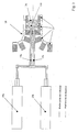
- Figs. 3 to 5 arrangements are schematically shown as using of the inventive idea, i. using the special ones Distribution devices, devices for the production of corrugated pipes constructed can be.
- FIGS. 3 to 5 a movable, from circulating, is on the right Molded halves 27 formed mold 28 shown.
- this movable form 28 are - according to the embodiment of FIG. 1 - two Distributing devices 13a, 13b arranged via supply channels 17a, 17b be fed.
- the inner and outer walls of the Multi-layered corrugated pipe made of different plastics. Accordingly, two extruders, namely an extruder 29a, which are the Plastic melt for the outer wall 11 supplies, as well as an extruder 29 b for Production of the plastic melt for the inner wall 12 is provided.
- Figs. 4 and 5 are also produced two-walled corrugated pipes.
- the inner and outer walls should be made consist of the same material, which is why only one extruder 29 is provided.
- a conventional distribution box 30th is provided, which over comparatively long supply channels 17a, 17b with the Distributor 13 a, 13 b is connected, the distribution of the out of the Extruder 29 exiting plastic flow in the embodiment of the 5 via a Y-distributor 31, to which directly the supply channels 17a, 17b.
- a Y-distributor 31 to which directly the supply channels 17a, 17b.
- the device described offers a variety of ways that Properties of pipes produced with the device as a function of to influence the plastic used.
Landscapes
- Engineering & Computer Science (AREA)
- Mechanical Engineering (AREA)
- Manufacturing & Machinery (AREA)
- Extrusion Moulding Of Plastics Or The Like (AREA)
- Rigid Pipes And Flexible Pipes (AREA)
- Shaping Of Tube Ends By Bending Or Straightening (AREA)
Applications Claiming Priority (3)
| Application Number | Priority Date | Filing Date | Title |
|---|---|---|---|
| DE10107191A DE10107191A1 (de) | 2001-02-16 | 2001-02-16 | Vorrichtung zur Herstellung von Kunststoffrohren |
| DE10107191 | 2001-02-16 | ||
| EP02712769A EP1360061B1 (fr) | 2001-02-16 | 2002-02-12 | Dispositif de realisation de tubes en plastique |
Related Parent Applications (2)
| Application Number | Title | Priority Date | Filing Date |
|---|---|---|---|
| EP02712769.5 Division | 2002-02-12 | ||
| EP02712769A Division EP1360061B1 (fr) | 2001-02-16 | 2002-02-12 | Dispositif de realisation de tubes en plastique |
Publications (3)
| Publication Number | Publication Date |
|---|---|
| EP1577075A2 true EP1577075A2 (fr) | 2005-09-21 |
| EP1577075A3 EP1577075A3 (fr) | 2009-09-16 |
| EP1577075B1 EP1577075B1 (fr) | 2010-08-18 |
Family
ID=7674231
Family Applications (2)
| Application Number | Title | Priority Date | Filing Date |
|---|---|---|---|
| EP05007210A Expired - Lifetime EP1577075B1 (fr) | 2001-02-16 | 2002-02-12 | Dispositif pour la production de tubes plastiques |
| EP02712769A Expired - Lifetime EP1360061B1 (fr) | 2001-02-16 | 2002-02-12 | Dispositif de realisation de tubes en plastique |
Family Applications After (1)
| Application Number | Title | Priority Date | Filing Date |
|---|---|---|---|
| EP02712769A Expired - Lifetime EP1360061B1 (fr) | 2001-02-16 | 2002-02-12 | Dispositif de realisation de tubes en plastique |
Country Status (9)
| Country | Link |
|---|---|
| US (1) | US7037098B2 (fr) |
| EP (2) | EP1577075B1 (fr) |
| CN (1) | CN1223449C (fr) |
| AT (2) | ATE477910T1 (fr) |
| CA (1) | CA2435029C (fr) |
| DE (4) | DE10107191A1 (fr) |
| ES (2) | ES2351086T3 (fr) |
| PT (1) | PT1577075E (fr) |
| WO (1) | WO2002066229A1 (fr) |
Families Citing this family (12)
| Publication number | Priority date | Publication date | Assignee | Title |
|---|---|---|---|---|
| DE10205843B4 (de) * | 2002-02-13 | 2004-11-25 | Battenfeld Extrusionstechnik Gmbh | Doppelstegdorn |
| CN2728745Y (zh) * | 2003-01-10 | 2005-09-28 | 曼夫瑞德·A·A·鲁波克 | 用于模制塑料管的装置 |
| DE102006037885A1 (de) | 2006-08-11 | 2008-02-14 | Unicor Gmbh | Spritzkopf für einen Corrugator |
| EP2116352B1 (fr) | 2008-05-09 | 2010-06-09 | Ralph-Peter Dr.-Ing. Hegler | Outil d'extrusion pour un dispositif pour la fabrication de tuyaux composites en matière synthétique avec des rainures obliques |
| DE102010046501B4 (de) * | 2010-09-24 | 2013-12-12 | Unitec Gmbh Technische Entwicklungen | Vorrichtung bzw. Werkzeug zum kontinuierlichen Herstellen von flexiblen ein- oder mehrlagigen und materialsparenden Kunststoff-Wellrohren in Verbindung mit Wellrohrformmaschinen und umlaufenden Formkokillen. |
| JP5088441B1 (ja) * | 2011-12-22 | 2012-12-05 | 富士ゼロックス株式会社 | 管状体の製造装置、管状体の製造方法 |
| CN104894533B (zh) * | 2015-04-01 | 2017-10-03 | 沈阳拓荆科技有限公司 | 一种半导体设备控温喷淋装置的星形传热介质通道结构 |
| CN105216268B (zh) * | 2015-11-12 | 2017-11-24 | 顾咏亮 | 用于制造木塑地板的模具 |
| DE102017105807B3 (de) * | 2017-03-17 | 2018-08-16 | Schlemmer Holding GmbH | Mehrkomponenten-Extrusionsspritzkopf, Mehrkomponenten-Extrusionsanlage und Verfahren zum Herstellen eines Verbundschlauchs |
| HUE048954T2 (hu) * | 2017-11-07 | 2020-09-28 | W Mueller Gmbh | Gyûrûs elosztó extrúziós tömlõfejhez, tömlõ alakú idomdarab hõre lágyuló mûanyagból történõ elõállításához |
| CN108859054B (zh) * | 2018-08-07 | 2023-12-05 | 江苏烨欣塑业有限公司 | 一种hdpe农田灌溉管制备方法、hdpe农田灌溉管及制作装置 |
| CN117863504B (zh) * | 2024-03-12 | 2024-05-14 | 四川鸿宇恒创塑料制品有限责任公司 | 一种聚氯乙烯管材挤出装置以及挤塑方法 |
Family Cites Families (16)
| Publication number | Priority date | Publication date | Assignee | Title |
|---|---|---|---|---|
| DE1964675A1 (de) * | 1969-12-23 | 1971-07-01 | Windmoeller & Hoelscher | Folienblaskopf zur Herstellung von Kunststoff-Schlauchfolien |
| US3743456A (en) * | 1971-08-20 | 1973-07-03 | Acme Hamilton Mfg Corp | Adjustable die heads for extruders and the like |
| US3809515A (en) * | 1972-03-03 | 1974-05-07 | Farrell Patent Co | Extrusion die for blowing plastic film |
| FR2180570A1 (en) * | 1972-04-21 | 1973-11-30 | Saint Gobain Pont A Mousson | Multiple screw extrusion dies - with independent flow and control downstream from each screw tip |
| DE2752932A1 (de) | 1977-11-26 | 1979-05-31 | Reifenhaeuser Kg | Ringspaltwerkzeug zum strangpressen von thermoplastischem kunststoff |
| US4201532A (en) * | 1978-08-02 | 1980-05-06 | Cole Robert J | Extrusion dies of spiral mandrel type |
| GB2193921B (en) * | 1986-08-15 | 1990-03-21 | Polysystem Machinery Mfg | Extrusion die for blown plastic film |
| DE3737588C3 (de) * | 1987-11-05 | 1993-12-23 | Corma Inc | Verfahren zum Herstellen eines innen glatten, außen gerippten Rohres aus extrudierbarem Kunststoff sowie Vorrichtung zur Durchführung des Verfahrens |
| US5460771A (en) * | 1992-10-16 | 1995-10-24 | Itt Corporation | Process for producing corrugated multi-layer tubing having layers of differing plastic characteristics |
| CA2183633C (fr) * | 1994-02-23 | 2006-08-22 | Edward K. Krause | Tube composite en fluoropolymere et sa fabrication |
| JP3471924B2 (ja) * | 1994-09-21 | 2003-12-02 | 呉羽化学工業株式会社 | スパイラルダイおよびこれを用いる積層体製造方法 |
| US5690972A (en) * | 1996-07-01 | 1997-11-25 | Macro Engineering & Technology Inc. | Annular co-extrusion die |
| DE19703492A1 (de) * | 1997-01-31 | 1998-08-06 | Bekum Maschf Gmbh | Verteiler für in einem Extruder plastifizierte Kunststoffschmelze für deren Aufteilung auf mehrere Beareitungswerkzeuge |
| US6116885A (en) * | 1997-03-21 | 2000-09-12 | Macro Engineering & Technology Inc. | Extrusion of plastic materials in multilayer tubular film |
| DE19835189C2 (de) * | 1998-08-04 | 2001-02-08 | Unicor Rohrsysteme Gmbh | Vorrichtung zur kontinuierlichen Herstellung von nahtlosen Kunststoffrohren |
| IT1319599B1 (it) * | 2000-12-20 | 2003-10-20 | Rosaldo Fare | Testa di melt-blown e procedimento ad alimentazione controllata per laproduzione di fibrille di materiale polimerico |
-
2001
- 2001-02-16 DE DE10107191A patent/DE10107191A1/de not_active Withdrawn
-
2002
- 2002-02-12 EP EP05007210A patent/EP1577075B1/fr not_active Expired - Lifetime
- 2002-02-12 EP EP02712769A patent/EP1360061B1/fr not_active Expired - Lifetime
- 2002-02-12 US US10/467,192 patent/US7037098B2/en not_active Expired - Lifetime
- 2002-02-12 PT PT05007210T patent/PT1577075E/pt unknown
- 2002-02-12 ES ES05007210T patent/ES2351086T3/es not_active Expired - Lifetime
- 2002-02-12 AT AT05007210T patent/ATE477910T1/de active
- 2002-02-12 ES ES02712769T patent/ES2252434T3/es not_active Expired - Lifetime
- 2002-02-12 DE DE20220574U patent/DE20220574U1/de not_active Expired - Lifetime
- 2002-02-12 CA CA002435029A patent/CA2435029C/fr not_active Expired - Lifetime
- 2002-02-12 WO PCT/DE2002/000493 patent/WO2002066229A1/fr not_active Ceased
- 2002-02-12 DE DE50205188T patent/DE50205188D1/de not_active Expired - Lifetime
- 2002-02-12 AT AT02712769T patent/ATE311969T1/de not_active IP Right Cessation
- 2002-02-12 DE DE50214600T patent/DE50214600D1/de not_active Expired - Lifetime
- 2002-02-12 CN CNB028050827A patent/CN1223449C/zh not_active Expired - Lifetime
Also Published As
| Publication number | Publication date |
|---|---|
| US7037098B2 (en) | 2006-05-02 |
| DE50214600D1 (de) | 2010-09-30 |
| CN1223449C (zh) | 2005-10-19 |
| EP1577075B1 (fr) | 2010-08-18 |
| EP1360061A1 (fr) | 2003-11-12 |
| PT1577075E (pt) | 2010-09-16 |
| US20040062829A1 (en) | 2004-04-01 |
| ATE477910T1 (de) | 2010-09-15 |
| ES2252434T3 (es) | 2006-05-16 |
| CA2435029C (fr) | 2007-05-01 |
| EP1577075A3 (fr) | 2009-09-16 |
| DE10107191A1 (de) | 2002-09-05 |
| CA2435029A1 (fr) | 2002-08-29 |
| ES2351086T3 (es) | 2011-01-31 |
| CN1491158A (zh) | 2004-04-21 |
| DE50205188D1 (de) | 2006-01-12 |
| WO2002066229A1 (fr) | 2002-08-29 |
| DE20220574U1 (de) | 2004-01-15 |
| ATE311969T1 (de) | 2005-12-15 |
| EP1360061B1 (fr) | 2005-12-07 |
Similar Documents
| Publication | Publication Date | Title |
|---|---|---|
| DE19835189C2 (de) | Vorrichtung zur kontinuierlichen Herstellung von nahtlosen Kunststoffrohren | |
| DE69425537T2 (de) | Schmelzblasdüse | |
| DE2839552C3 (de) | Düsenkopf zum Herstellen von Kunststoffgranulat | |
| DE4141497A1 (de) | Verfahren und vorrichtung zur formung eines gegenstandes mit vielzellenfoermiger dichte und/oder geometrie | |
| DE69319835T2 (de) | Vorrichtung und Verfahren zum Herstellen eines mehrschichtiges Laminatfilms | |
| EP1360061B1 (fr) | Dispositif de realisation de tubes en plastique | |
| DE19535749C1 (de) | Extrusionskopf zur Herstellung von schlauch- oder rohrförmigen Vorformlingen aus extrudierbarem Kunststoff | |
| DE3832566A1 (de) | Verfahren zum herstellen gefuellter fluessigkeitsbehaelter aus thermoplastischem kunststoff sowie extrusionskopf | |
| DE69711797T2 (de) | Koextrusionsadapter | |
| EP1213122A1 (fr) | Tête d'extrusion avec ouvertoure annulaire pour la fabrication de feuilles soufflées de au moins un flux de matière thermoplastique | |
| DE69708651T2 (de) | Extrusionsvorrichtung und verfahren | |
| DE29810317U1 (de) | Formblock zur Verwendung in einem beweglichen Formtunnel | |
| DE102017107567A1 (de) | Mehrschichtwerkzeug | |
| DE3921631C2 (fr) | ||
| DE1959348A1 (de) | Verfahren und Vorrichtung zum Extrudieren von thermoplastischem Kunststoff | |
| DE3843388A1 (de) | Strangpressduese zum extrudieren keramischer koerper mit wabenartiger struktur | |
| EP1916087A1 (fr) | Dispositif destiné à l'application de matière synthétique sur une pièce à usiner | |
| DE2839967C2 (fr) | ||
| EP2049318B1 (fr) | Tête d'injection pour une machine à onduler pour la fabrication de tubes en matière plastique | |
| WO2002036327A1 (fr) | Dispositif de realisation d'une membrane polymere | |
| EP0243516A1 (fr) | Dispositif pour l'extrusion d'un tube en matière plastique à double paroi | |
| DE102006050543B4 (de) | Vorrichtung zur Aufbringung von Kunststoff auf ein Werkstück | |
| DE69524950T2 (de) | Verbesserte kalibrierstange für eine verteileranordnung | |
| DE102007007139A1 (de) | Vorrichtung zur Aufbringung von Kunststoff auf ein Werkstück | |
| DE102017107563A1 (de) | Mehrschichtwerkzeug |
Legal Events
| Date | Code | Title | Description |
|---|---|---|---|
| PUAI | Public reference made under article 153(3) epc to a published international application that has entered the european phase |
Free format text: ORIGINAL CODE: 0009012 |
|
| AC | Divisional application: reference to earlier application |
Ref document number: 1360061 Country of ref document: EP Kind code of ref document: P |
|
| AK | Designated contracting states |
Kind code of ref document: A2 Designated state(s): AT BE CH CY DE DK ES FI FR GB GR IE IT LI LU MC NL PT SE TR |
|
| PUAL | Search report despatched |
Free format text: ORIGINAL CODE: 0009013 |
|
| AK | Designated contracting states |
Kind code of ref document: A3 Designated state(s): AT BE CH CY DE DK ES FI FR GB GR IE IT LI LU MC NL PT SE TR |
|
| 17P | Request for examination filed |
Effective date: 20091228 |
|
| GRAP | Despatch of communication of intention to grant a patent |
Free format text: ORIGINAL CODE: EPIDOSNIGR1 |
|
| AKX | Designation fees paid |
Designated state(s): AT BE CH CY DE DK ES FI FR GB GR IE IT LI LU MC NL PT SE TR |
|
| GRAS | Grant fee paid |
Free format text: ORIGINAL CODE: EPIDOSNIGR3 |
|
| GRAA | (expected) grant |
Free format text: ORIGINAL CODE: 0009210 |
|
| AC | Divisional application: reference to earlier application |
Ref document number: 1360061 Country of ref document: EP Kind code of ref document: P |
|
| AK | Designated contracting states |
Kind code of ref document: B1 Designated state(s): AT BE CH CY DE DK ES FI FR GB GR IE IT LI LU MC NL PT SE TR |
|
| REG | Reference to a national code |
Ref country code: GB Ref legal event code: FG4D Free format text: NOT ENGLISH |
|
| REG | Reference to a national code |
Ref country code: CH Ref legal event code: EP |
|
| REG | Reference to a national code |
Ref country code: IE Ref legal event code: FG4D Free format text: LANGUAGE OF EP DOCUMENT: GERMAN |
|
| REG | Reference to a national code |
Ref country code: PT Ref legal event code: SC4A Free format text: AVAILABILITY OF NATIONAL TRANSLATION Effective date: 20100910 |
|
| REF | Corresponds to: |
Ref document number: 50214600 Country of ref document: DE Date of ref document: 20100930 Kind code of ref document: P |
|
| REG | Reference to a national code |
Ref country code: SE Ref legal event code: TRGR |
|
| REG | Reference to a national code |
Ref country code: NL Ref legal event code: VDEP Effective date: 20100818 |
|
| PG25 | Lapsed in a contracting state [announced via postgrant information from national office to epo] |
Ref country code: FI Free format text: LAPSE BECAUSE OF FAILURE TO SUBMIT A TRANSLATION OF THE DESCRIPTION OR TO PAY THE FEE WITHIN THE PRESCRIBED TIME-LIMIT Effective date: 20100818 |
|
| REG | Reference to a national code |
Ref country code: ES Ref legal event code: FG2A Effective date: 20110119 |
|
| PG25 | Lapsed in a contracting state [announced via postgrant information from national office to epo] |
Ref country code: CY Free format text: LAPSE BECAUSE OF FAILURE TO SUBMIT A TRANSLATION OF THE DESCRIPTION OR TO PAY THE FEE WITHIN THE PRESCRIBED TIME-LIMIT Effective date: 20100818 |
|
| REG | Reference to a national code |
Ref country code: IE Ref legal event code: FD4D |
|
| PG25 | Lapsed in a contracting state [announced via postgrant information from national office to epo] |
Ref country code: GR Free format text: LAPSE BECAUSE OF FAILURE TO SUBMIT A TRANSLATION OF THE DESCRIPTION OR TO PAY THE FEE WITHIN THE PRESCRIBED TIME-LIMIT Effective date: 20101119 Ref country code: NL Free format text: LAPSE BECAUSE OF FAILURE TO SUBMIT A TRANSLATION OF THE DESCRIPTION OR TO PAY THE FEE WITHIN THE PRESCRIBED TIME-LIMIT Effective date: 20100818 |
|
| PG25 | Lapsed in a contracting state [announced via postgrant information from national office to epo] |
Ref country code: DK Free format text: LAPSE BECAUSE OF FAILURE TO SUBMIT A TRANSLATION OF THE DESCRIPTION OR TO PAY THE FEE WITHIN THE PRESCRIBED TIME-LIMIT Effective date: 20100818 Ref country code: IE Free format text: LAPSE BECAUSE OF FAILURE TO SUBMIT A TRANSLATION OF THE DESCRIPTION OR TO PAY THE FEE WITHIN THE PRESCRIBED TIME-LIMIT Effective date: 20100818 |
|
| PLBE | No opposition filed within time limit |
Free format text: ORIGINAL CODE: 0009261 |
|
| STAA | Information on the status of an ep patent application or granted ep patent |
Free format text: STATUS: NO OPPOSITION FILED WITHIN TIME LIMIT |
|
| 26N | No opposition filed |
Effective date: 20110519 |
|
| BERE | Be: lapsed |
Owner name: UNICOR G.M.B.H. Effective date: 20110228 |
|
| REG | Reference to a national code |
Ref country code: DE Ref legal event code: R097 Ref document number: 50214600 Country of ref document: DE Effective date: 20110519 |
|
| PG25 | Lapsed in a contracting state [announced via postgrant information from national office to epo] |
Ref country code: MC Free format text: LAPSE BECAUSE OF NON-PAYMENT OF DUE FEES Effective date: 20110228 |
|
| REG | Reference to a national code |
Ref country code: CH Ref legal event code: PL |
|
| GBPC | Gb: european patent ceased through non-payment of renewal fee |
Effective date: 20110212 |
|
| PG25 | Lapsed in a contracting state [announced via postgrant information from national office to epo] |
Ref country code: LI Free format text: LAPSE BECAUSE OF NON-PAYMENT OF DUE FEES Effective date: 20110228 Ref country code: CH Free format text: LAPSE BECAUSE OF NON-PAYMENT OF DUE FEES Effective date: 20110228 |
|
| PG25 | Lapsed in a contracting state [announced via postgrant information from national office to epo] |
Ref country code: BE Free format text: LAPSE BECAUSE OF NON-PAYMENT OF DUE FEES Effective date: 20110228 |
|
| PG25 | Lapsed in a contracting state [announced via postgrant information from national office to epo] |
Ref country code: GB Free format text: LAPSE BECAUSE OF NON-PAYMENT OF DUE FEES Effective date: 20110212 |
|
| REG | Reference to a national code |
Ref country code: AT Ref legal event code: MM01 Ref document number: 477910 Country of ref document: AT Kind code of ref document: T Effective date: 20110212 |
|
| PG25 | Lapsed in a contracting state [announced via postgrant information from national office to epo] |
Ref country code: AT Free format text: LAPSE BECAUSE OF NON-PAYMENT OF DUE FEES Effective date: 20110212 |
|
| PG25 | Lapsed in a contracting state [announced via postgrant information from national office to epo] |
Ref country code: LU Free format text: LAPSE BECAUSE OF NON-PAYMENT OF DUE FEES Effective date: 20110212 |
|
| REG | Reference to a national code |
Ref country code: FR Ref legal event code: PLFP Year of fee payment: 15 |
|
| REG | Reference to a national code |
Ref country code: FR Ref legal event code: PLFP Year of fee payment: 16 |
|
| REG | Reference to a national code |
Ref country code: FR Ref legal event code: PLFP Year of fee payment: 17 |
|
| REG | Reference to a national code |
Ref country code: DE Ref legal event code: R079 Ref document number: 50214600 Country of ref document: DE Free format text: PREVIOUS MAIN CLASS: B29C0047700000 Ipc: B29C0048695000 |
|
| PGFP | Annual fee paid to national office [announced via postgrant information from national office to epo] |
Ref country code: PT Payment date: 20210129 Year of fee payment: 20 Ref country code: FR Payment date: 20210217 Year of fee payment: 20 Ref country code: IT Payment date: 20210226 Year of fee payment: 20 |
|
| PGFP | Annual fee paid to national office [announced via postgrant information from national office to epo] |
Ref country code: ES Payment date: 20210323 Year of fee payment: 20 Ref country code: SE Payment date: 20210222 Year of fee payment: 20 Ref country code: TR Payment date: 20210205 Year of fee payment: 20 Ref country code: DE Payment date: 20201217 Year of fee payment: 20 |
|
| REG | Reference to a national code |
Ref country code: DE Ref legal event code: R071 Ref document number: 50214600 Country of ref document: DE |
|
| REG | Reference to a national code |
Ref country code: SE Ref legal event code: EUG |
|
| REG | Reference to a national code |
Ref country code: ES Ref legal event code: FD2A Effective date: 20220526 |
|
| PG25 | Lapsed in a contracting state [announced via postgrant information from national office to epo] |
Ref country code: PT Free format text: LAPSE BECAUSE OF EXPIRATION OF PROTECTION Effective date: 20220222 |
|
| PG25 | Lapsed in a contracting state [announced via postgrant information from national office to epo] |
Ref country code: ES Free format text: LAPSE BECAUSE OF EXPIRATION OF PROTECTION Effective date: 20220213 |