EP1577138B1 - Procédé de mise en ouevre d'un véhicule hybride - Google Patents
Procédé de mise en ouevre d'un véhicule hybride Download PDFInfo
- Publication number
- EP1577138B1 EP1577138B1 EP04028790A EP04028790A EP1577138B1 EP 1577138 B1 EP1577138 B1 EP 1577138B1 EP 04028790 A EP04028790 A EP 04028790A EP 04028790 A EP04028790 A EP 04028790A EP 1577138 B1 EP1577138 B1 EP 1577138B1
- Authority
- EP
- European Patent Office
- Prior art keywords
- torque
- drive torque
- operating state
- internal combustion
- fired mode
- Prior art date
- Legal status (The legal status is an assumption and is not a legal conclusion. Google has not performed a legal analysis and makes no representation as to the accuracy of the status listed.)
- Expired - Lifetime
Links
Images
Classifications
-
- B—PERFORMING OPERATIONS; TRANSPORTING
- B60—VEHICLES IN GENERAL
- B60W—CONJOINT CONTROL OF VEHICLE SUB-UNITS OF DIFFERENT TYPE OR DIFFERENT FUNCTION; CONTROL SYSTEMS SPECIALLY ADAPTED FOR HYBRID VEHICLES; ROAD VEHICLE DRIVE CONTROL SYSTEMS FOR PURPOSES NOT RELATED TO THE CONTROL OF A PARTICULAR SUB-UNIT
- B60W20/00—Control systems specially adapted for hybrid vehicles
-
- B—PERFORMING OPERATIONS; TRANSPORTING
- B60—VEHICLES IN GENERAL
- B60K—ARRANGEMENT OR MOUNTING OF PROPULSION UNITS OR OF TRANSMISSIONS IN VEHICLES; ARRANGEMENT OR MOUNTING OF PLURAL DIVERSE PRIME-MOVERS IN VEHICLES; AUXILIARY DRIVES FOR VEHICLES; INSTRUMENTATION OR DASHBOARDS FOR VEHICLES; ARRANGEMENTS IN CONNECTION WITH COOLING, AIR INTAKE, GAS EXHAUST OR FUEL SUPPLY OF PROPULSION UNITS IN VEHICLES
- B60K6/00—Arrangement or mounting of plural diverse prime-movers for mutual or common propulsion, e.g. hybrid propulsion systems comprising electric motors and internal combustion engines
- B60K6/20—Arrangement or mounting of plural diverse prime-movers for mutual or common propulsion, e.g. hybrid propulsion systems comprising electric motors and internal combustion engines the prime-movers consisting of electric motors and internal combustion engines, e.g. HEVs
- B60K6/42—Arrangement or mounting of plural diverse prime-movers for mutual or common propulsion, e.g. hybrid propulsion systems comprising electric motors and internal combustion engines the prime-movers consisting of electric motors and internal combustion engines, e.g. HEVs characterised by the architecture of the hybrid electric vehicle
- B60K6/48—Parallel type
-
- B—PERFORMING OPERATIONS; TRANSPORTING
- B60—VEHICLES IN GENERAL
- B60W—CONJOINT CONTROL OF VEHICLE SUB-UNITS OF DIFFERENT TYPE OR DIFFERENT FUNCTION; CONTROL SYSTEMS SPECIALLY ADAPTED FOR HYBRID VEHICLES; ROAD VEHICLE DRIVE CONTROL SYSTEMS FOR PURPOSES NOT RELATED TO THE CONTROL OF A PARTICULAR SUB-UNIT
- B60W10/00—Conjoint control of vehicle sub-units of different type or different function
- B60W10/04—Conjoint control of vehicle sub-units of different type or different function including control of propulsion units
- B60W10/06—Conjoint control of vehicle sub-units of different type or different function including control of propulsion units including control of combustion engines
-
- B—PERFORMING OPERATIONS; TRANSPORTING
- B60—VEHICLES IN GENERAL
- B60W—CONJOINT CONTROL OF VEHICLE SUB-UNITS OF DIFFERENT TYPE OR DIFFERENT FUNCTION; CONTROL SYSTEMS SPECIALLY ADAPTED FOR HYBRID VEHICLES; ROAD VEHICLE DRIVE CONTROL SYSTEMS FOR PURPOSES NOT RELATED TO THE CONTROL OF A PARTICULAR SUB-UNIT
- B60W10/00—Conjoint control of vehicle sub-units of different type or different function
- B60W10/04—Conjoint control of vehicle sub-units of different type or different function including control of propulsion units
- B60W10/08—Conjoint control of vehicle sub-units of different type or different function including control of propulsion units including control of electric propulsion units, e.g. motors or generators
-
- F—MECHANICAL ENGINEERING; LIGHTING; HEATING; WEAPONS; BLASTING
- F02—COMBUSTION ENGINES; HOT-GAS OR COMBUSTION-PRODUCT ENGINE PLANTS
- F02P—IGNITION, OTHER THAN COMPRESSION IGNITION, FOR INTERNAL-COMBUSTION ENGINES; TESTING OF IGNITION TIMING IN COMPRESSION-IGNITION ENGINES
- F02P5/00—Advancing or retarding ignition; Control therefor
- F02P5/04—Advancing or retarding ignition; Control therefor automatically, as a function of the working conditions of the engine or vehicle or of the atmospheric conditions
- F02P5/145—Advancing or retarding ignition; Control therefor automatically, as a function of the working conditions of the engine or vehicle or of the atmospheric conditions using electrical means
- F02P5/15—Digital data processing
- F02P5/1502—Digital data processing using one central computing unit
- F02P5/1504—Digital data processing using one central computing unit with particular means during a transient phase, e.g. acceleration, deceleration, gear change
-
- B—PERFORMING OPERATIONS; TRANSPORTING
- B60—VEHICLES IN GENERAL
- B60L—PROPULSION OF ELECTRICALLY-PROPELLED VEHICLES; SUPPLYING ELECTRIC POWER FOR AUXILIARY EQUIPMENT OF ELECTRICALLY-PROPELLED VEHICLES; ELECTRODYNAMIC BRAKE SYSTEMS FOR VEHICLES IN GENERAL; MAGNETIC SUSPENSION OR LEVITATION FOR VEHICLES; MONITORING OPERATING VARIABLES OF ELECTRICALLY-PROPELLED VEHICLES; ELECTRIC SAFETY DEVICES FOR ELECTRICALLY-PROPELLED VEHICLES
- B60L2240/00—Control parameters of input or output; Target parameters
- B60L2240/40—Drive Train control parameters
- B60L2240/48—Drive Train control parameters related to transmissions
- B60L2240/486—Operating parameters
-
- B—PERFORMING OPERATIONS; TRANSPORTING
- B60—VEHICLES IN GENERAL
- B60W—CONJOINT CONTROL OF VEHICLE SUB-UNITS OF DIFFERENT TYPE OR DIFFERENT FUNCTION; CONTROL SYSTEMS SPECIALLY ADAPTED FOR HYBRID VEHICLES; ROAD VEHICLE DRIVE CONTROL SYSTEMS FOR PURPOSES NOT RELATED TO THE CONTROL OF A PARTICULAR SUB-UNIT
- B60W2710/00—Output or target parameters relating to a particular sub-units
- B60W2710/06—Combustion engines, Gas turbines
- B60W2710/0616—Position of fuel or air injector
-
- B—PERFORMING OPERATIONS; TRANSPORTING
- B60—VEHICLES IN GENERAL
- B60W—CONJOINT CONTROL OF VEHICLE SUB-UNITS OF DIFFERENT TYPE OR DIFFERENT FUNCTION; CONTROL SYSTEMS SPECIALLY ADAPTED FOR HYBRID VEHICLES; ROAD VEHICLE DRIVE CONTROL SYSTEMS FOR PURPOSES NOT RELATED TO THE CONTROL OF A PARTICULAR SUB-UNIT
- B60W2710/00—Output or target parameters relating to a particular sub-units
- B60W2710/10—Change speed gearings
- B60W2710/105—Output torque
-
- F—MECHANICAL ENGINEERING; LIGHTING; HEATING; WEAPONS; BLASTING
- F02—COMBUSTION ENGINES; HOT-GAS OR COMBUSTION-PRODUCT ENGINE PLANTS
- F02D—CONTROLLING COMBUSTION ENGINES
- F02D2250/00—Engine control related to specific problems or objectives
- F02D2250/18—Control of the engine output torque
- F02D2250/21—Control of the engine output torque during a transition between engine operation modes or states
-
- F—MECHANICAL ENGINEERING; LIGHTING; HEATING; WEAPONS; BLASTING
- F02—COMBUSTION ENGINES; HOT-GAS OR COMBUSTION-PRODUCT ENGINE PLANTS
- F02D—CONTROLLING COMBUSTION ENGINES
- F02D2250/00—Engine control related to specific problems or objectives
- F02D2250/18—Control of the engine output torque
- F02D2250/24—Control of the engine output torque by using an external load, e.g. a generator
-
- Y—GENERAL TAGGING OF NEW TECHNOLOGICAL DEVELOPMENTS; GENERAL TAGGING OF CROSS-SECTIONAL TECHNOLOGIES SPANNING OVER SEVERAL SECTIONS OF THE IPC; TECHNICAL SUBJECTS COVERED BY FORMER USPC CROSS-REFERENCE ART COLLECTIONS [XRACs] AND DIGESTS
- Y02—TECHNOLOGIES OR APPLICATIONS FOR MITIGATION OR ADAPTATION AGAINST CLIMATE CHANGE
- Y02T—CLIMATE CHANGE MITIGATION TECHNOLOGIES RELATED TO TRANSPORTATION
- Y02T10/00—Road transport of goods or passengers
- Y02T10/10—Internal combustion engine [ICE] based vehicles
- Y02T10/40—Engine management systems
-
- Y—GENERAL TAGGING OF NEW TECHNOLOGICAL DEVELOPMENTS; GENERAL TAGGING OF CROSS-SECTIONAL TECHNOLOGIES SPANNING OVER SEVERAL SECTIONS OF THE IPC; TECHNICAL SUBJECTS COVERED BY FORMER USPC CROSS-REFERENCE ART COLLECTIONS [XRACs] AND DIGESTS
- Y02—TECHNOLOGIES OR APPLICATIONS FOR MITIGATION OR ADAPTATION AGAINST CLIMATE CHANGE
- Y02T—CLIMATE CHANGE MITIGATION TECHNOLOGIES RELATED TO TRANSPORTATION
- Y02T10/00—Road transport of goods or passengers
- Y02T10/60—Other road transportation technologies with climate change mitigation effect
- Y02T10/62—Hybrid vehicles
Definitions
- the invention relates to a method for operating a hybrid motor vehicle with an internal combustion engine and at least one electric machine, wherein the transition from a first operating state with a first drive torque in a second operating state with a lower second drive torque before switching to the second operating state, a drive torque of Internal combustion engine is reduced by reducing a cylinder filling and / or closing a throttle valve, according to the preamble of patent claim 1.
- a problem which is known in an internal combustion engine is jerky vibrations when changing over from the fired operation to the unsprung mode (fuel cutoff).
- the fuel injection or possibly also the ignition can not be stopped abruptly, if the driver, starting from a torque request (accelerator pedal partially or fully depressed) on the engine drag torque (fuel cut or accelerator pedal in position equal to zero percent) is changed.
- the torque jump resulting from the difference between the engine torque during fired operation and the engine drag torque increases with higher drive torque before the fuel cutoff.
- a dashpot function is implemented in today running engine controls usually by a gradual torque reduction with fired engine according to a predeterminable time course, for example by Zylinderhellungsabbau (closing the throttle, gasoline engine directly or indirectly injecting in homogeneous operation) and / or reducing the injection mass (direct injection gasoline engine in stratified operation or diesel engine), first the moment is lowered to the minimum possible value, and then to switch from the lowest possible moment in fired operation in the fuel cut.
- the minimum representable torque in the fired operation (during the dashpot sequence and immediately before the overrun fuel cut-off) is determined in a homogeneously operated gasoline engine usually by the minimum allowable filling in combination with the associated latest possible ignition angle. If lower cylinder fillings are adjusted and / or the ignition angle is delayed further, the combustion limit is undershot, that is, the combustion in the cylinder then runs only insufficiently or not at all.
- a drive system for a motor vehicle with an internal combustion engine, an electric machine and a device for fuel cut of the internal combustion engine is known, wherein the electric machine applied to the internal combustion engine with a torque such that a jerk-reducing effect is brought about.
- the electric machine is activated by means of the activating and Deactivation signal of the fuel cut-off controlled.
- the electrical machine can act advantageously as a motor and as a generator, depending on whether the jerk to be damped stems from the activation or deactivation of fuel cut.
- the invention has for its object to provide a method of the above type with improved dashpot function available.
- a firing angle is set in dependence on the current cylinder filling and / or depending on the current position of the throttle to a value which for this momentary Cylinder charge and / or for this current position of the throttle optimum or approximately optimal efficiency of the internal combustion engine results, in addition, the drive torque is set against a counteracting the drive torque acting counter-torque of at least one of the electric machines.
- At least one of the electrical machines to reduce the drive torque is operated as a generator, wherein a generated electrical energy in an energy storage, such as a battery storage or a Condenser memory is stored.
- an energy storage such as a battery storage or a Condenser memory
- this electrical energy can be used in the further course of the journey for an electromotive drive support or the supply of the vehicle electrical system.
- at least part of the energy otherwise converted by ignition retard adjustment in many operating phases without benefit into exhaust gas or coolant heat is used, which increases the overall efficiency.
- the first operating state is a fired operation
- the second operating state an unfired operation
- the second drive torque is a motor drag torque.
- a firing of the internal combustion engine is interrupted and transferred to an unfired operation, when the cylinder filling reaches the combustion limit at at least almost optimal efficiency ignition angle.
- the cylinder charge and the ignition angle are preferably set to respective values at a greater distance from the firing limit immediately before the transition to unfired operation.
- the cylinder charge is increased by 0.5% to 6%, in particular 1% to 3%, starting from a value at the combustion limit and / or the ignition angle is initiated immediately before the transition to unfired operation from a value at the burning limit by at least 3 ° CA, in particular at least 6 ° CA adjusted to early.
- a transition to unfurnished operation without torque jump with correspondingly increased ride comfort is achieved in that, after the transition to unfired operation, at least one of the electrical machines generates a driving torque in a drive train of the internal combustion engine such that a time characteristic of the drive torque changes from the momentary drive torque Time of switching to unfired operation to a motor drag torque in unfired operation of the engine is infinitely variable.
- the first operating state is a drive with a first gear ratio and the second operating state is a drive with a second gear ratio different from the first gear ratio.
- the drive torque is reduced via a Zündwinkeleingriff the transition to the second operating state for a predetermined period of, for example, 10 ms to 100 ms.
- a desired torque curve over time is predetermined and generates the electric machine during the reduction of the drive torque such a counter-torque that an actual curve of the drive torque over time follows the desired torque curve.
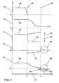
- FIG. 1 A graphical representation of the time course of accelerator pedal position, cylinder filling, ignition angle, torque, which is applied by an electric machine, and total drive torque in the drive train.
- the inventive method for operating a hybrid vehicle with an internal combustion engine and, for example, a coupled electric machine is graphically illustrated in the single FIG.
- a vertical axis at 10 is an angle of pedal position in percent [%], at 12 a relative cylinder fill in percent [%] (current value relative to the maximum possible cylinder fill), at 14 a cylinder angle in degrees crank angle [° KW], at 16 a torque generated by the electric machine in the drive train in Newton-meter [Nm] and at 18 an entire drive torque in the drive train in Newton-meter [Nm] plotted.
- An arrow 20 indicates an adjustment of the ignition angle 14 to early and an arrow 22 indicates an adjustment of the ignition angle 14 to late.
- Graph 26 illustrates the progression of pedal position 10 over time
- graph 28 illustrates the progression of relative cylinder fill 12 over time
- graph 30 illustrates the progression of firing angle 14 over time
- graph 32 illustrates the progression of Moment 16 of the electric machine over time 24
- a graph 34 illustrates the course of the entire drive torque 18 over time 24th
- a fuel cut ie an unfired operation of the internal combustion engine, requested due to the pedal position 0% and it follows the reduction of the drive torque 18 according to graph 34 (dashpot function).
- the overrun fuel cutoff takes place, for example, in that the fuel supply to the internal combustion engine is interrupted.
- the graph 30 which illustrates the time profile of the ignition angle 14 according to the inventive method
- dashed line 40 a time profile of the ignition angle 14 according to a known in the prior art method for reducing the drive torque 18 is shown.
- the drive torque 18 when the drive torque 18 is reduced in accordance with a predetermined time curve, as illustrated by graph 34, which is also referred to as "dashpot function", the drive torque 18 is initially similar to the reduction of the cylinder charge 12 (graph 28) or the closing of the throttle valve (not shown) to reduce.
- the invention is additionally another Adjusting the actual torque to the target curve 34 via torque interventions of the electric machine provided, wherein in the period from t 1 36 to t 2 38, the ignition angle 14 (graph 30) for the internal combustion engine at each operating point, ie in particular at each setting of the cylinder filling or the throttle valve, optimal efficiency or approximately optimal efficiency is set.
- the electric machine After the time t 1 36, ie immediately after the request of the overrun operation, the electric machine generates a negative drive torque according to graph 32, while the cylinder filling 12 is slowly degraded according to graph 28.
- the ignition angle 14 is kept at a level which is optimum for the respective cylinder charge 12, ie the ignition angle 14 is adjusted with increasing degradation of the cylinder charge 12 (arrow 20).
- the dashpot function 34 After the time t 2 38, ie after the beginning of the fuel cut, the dashpot function 34 still has a value for the total drive torque 18, which is higher than a value of a motor drag torque 42, so that in the conventional method of fuel cut 44 comes to a moment jump. According to the invention, it is additionally optionally provided that the electric machine immediately after the time t 2 38 generates a positive, with time decreasing drive torque, so that a stepless transition from the total drive torque 18 at time t 2 38 is achieved on the engine drag torque 42 ,
- the electrical energy generated by the generator operation of the electric machine in the period between t 1 36 and t 2 38 is preferably stored (with the corresponding efficiencies) in an electrical energy storage and can then in the further course of the journey for an electromotive drive support or the supply of Vehicle electrical system can be used.
- the electrical energy storage is, for example, a battery storage and / or a capacitor storage.
- This energy conversion process during the regenerative operation of the electric machine typically lasts only for 200 ms to 800 ms, so that offers a capacitor storage for the use of electrical energy generated because this electrical energy with good efficiencies and in these short phases with high Can store powers so that the realizable by the electric machine regenerative torque or counter-torque is not limited by the performance of the energy storage.
- the torque reduction can be carried out until the engine drag torque 42 by means of the electric machine, as previously explained and shown in the single Figure.
- circuit 46 so that a transition from the fired in the unfired operation at the time t 2 38 no more torque jump occurs, which further improves ride comfort compared to today, possibly also in direct injection gasoline engines in stratified charge mode or diesel engines.
- the time t 2 38 in which the firing of the internal combustion engine is interrupted, corresponds to that point in time at which the cylinder filling 12 reaches the firing limit at (at least almost) optimum firing angle.
- the electric machine changes from a negative regenerative to a positive (motor) moment.
- the desired torque curve 34 can also be adjusted so that the entire dashpot function 34 runs in the same time as in the conventional method.
- cylinder filling 12 and firing angle 14 are set immediately before the transition to the fuel cut-off at time t 2 38 to values which have a greater distance from the combustion limit of a homogeneously operated gasoline engine.
- the relative cylinder charge 12 is increased by 0.5 to 6 percent, preferably by 1 to 3 percent, and / or - if the firing angle is retarded here is - the firing angle by at least 3 degrees crank angle, preferably adjusted by at least 6 degrees crank angle to early (in each case compared to today's standard running or based on the latest possible ignition angle immediately before the time t 2 38).
- the novel realization of the dashpot function 34 can also be used if subsequently, ie at time t 2 38, no fuel cut sondem z. B. due to low engine speed or component protection reasons, the fired operation is maintained with minimal drive torque.
- the method described above can in principle also be used in switching operations of automated transmissions, such as, for example, automatic torque converters, direct-shift transmissions or dual-clutch transmissions.
- the switching times of automatic transmissions must be extremely short in order to ensure a corresponding driving comfort.
- the engine torque must be reduced or the engine and transmission speeds must be synchronized for the shifting process.
- the filling path of the internal combustion engine is usually not fast enough, so that here at high cylinder fillings must be worked with sometimes extremely retarded ignition angles in order to reduce the drive torque generated by the internal combustion engine accordingly.
- the electric machine instead of the Zündwinkelversticiantitch for the torque reduction and the speed reduction (also for engine speed increase in downshifts) can be used in analog forms as in the dashpot function described above. Since in this case, in addition, the catalyst load or the fuel consumption is reduced by dispensing with a mixture enrichment at even high air mass flows, there are further significant advantages for the design of the exhaust aftertreatment system and the overall efficiency of the drive.
- Vehicles with lean-running internal combustion engines in the new European driving cycle NEDC with thermally undamaged catalysts (with a stored sulfur mass less than 0.2 g / l catalyst volume) and a temporally fired lean operating component (without deceleration phases) with lambda> 1.15 of at least 250 seconds (in particular at least 350 seconds) achieve HC emissions of less than 0.07 g / km and a NO x emission of less than 0.05 g / km, today the prior art equips with catalysts containing noble metal contents of greater than or equal to 100 g / have 3 ft.
- the noble metal content of at least one catalyst can be less than 100 g / ft 3 , in particular less than or equal to 80 g / ft 3 and preferably less than or equal to 60 / 40/20/10 g / ft 3 be lowered without increasing the emissions in the NEDC with increasing vehicle mileage compared to the original design with higher precious metal content and without the inventive method deteriorate.
- the above-described method makes it possible to reduce the noble metal content of the catalysts starting from the values stated today as standard and 10%, preferably by 20% and especially preferably by 30%, without the emissions in NEDC increasing Vehicle mileage over the original design with higher precious metal content and without the process of the invention deteriorate.
- the precious metal content can be lowered to less than or equal to 40/30/20/10/5 g / ft 3 .
Landscapes
- Engineering & Computer Science (AREA)
- Chemical & Material Sciences (AREA)
- Combustion & Propulsion (AREA)
- Mechanical Engineering (AREA)
- Transportation (AREA)
- Automation & Control Theory (AREA)
- Signal Processing (AREA)
- General Engineering & Computer Science (AREA)
- Theoretical Computer Science (AREA)
- Control Of Vehicle Engines Or Engines For Specific Uses (AREA)
- Electrical Control Of Air Or Fuel Supplied To Internal-Combustion Engine (AREA)
- Auxiliary Drives, Propulsion Controls, And Safety Devices (AREA)
- Control Of Throttle Valves Provided In The Intake System Or In The Exhaust System (AREA)
- Electrical Control Of Ignition Timing (AREA)
Claims (14)
- Procédé pour faire fonctionner un véhicule hybride, comprenant un moteur à combustion interne et au moins un moteur électrique, dans lequel, lors du passage d'un premier état de fonctionnement avec un premier couple d'entraînement dans un deuxième état de fonctionnement avec un deuxième couple de fonctionnement plus faible, avant de commuter dans le deuxième étant de fonctionnement, un couple d'entraînement du moteur à combustion interne est réduit par une diminution d'un remplissage du cylindre et/ou une fermeture d'un clapet d'étranglement, caractérisé en ce que pendant la réduction du couple d'entraînement au moyen de la diminution du remplissage du cylindre et/ou de la fermeture du clapet d'étranglement, un angle d'allumage est ajusté en fonction du remplissage momentané du cylindre et/ou de la position momentanée du clapet d'étranglement, à une valeur qui produit, pour ce remplissage momentané du cylindre et/ou cette position momentanée du clapet d'étranglement, un rendement optimal ou pratiquement optimal du moteur à combustion interne, le couple d'entraînement étant en outre réduit par le biais d'un couple conjugué d'au moins l'un des moteurs électriques, agissant à l'encontre du couple d'entraînement.
- Procédé selon la revendication 1, caractérisé en ce qu'au moins l'un des moteurs électriques est entraîné en tant que générateur pour réduire le couple d'entraînement, une énergie électrique produite étant stockée dans un accumulateur d'énergie.
- Procédé selon la revendication 1, caractérisé en ce que l'accumulateur d'énergie est un accumulateur à batterie ou un accumulateur à condensateur.
- Procédé selon au moins l'une quelconque des revendications précédentes, caractérisé en ce que le premier état de fonctionnement est un fonctionnement en service, le deuxième état de fonctionnement est un fonctionnement hors service et le deuxième couple d'entraînement est un couple d'inertie de moteur.
- Procédé selon la revendication 4, caractérisé en ce que le fonctionnement de service du moteur à combustion interne est interrompu et il passe au fonctionnement hors service lorsque le remplissage du cylindre atteint la limite de combustion pour un angle d'allumage au moins pratiquement optimal en termes de rendement.
- Procédé selon la revendication 5, caractérisé en ce qu'immédiatement avant le passage dans le fonctionnement hors service, le remplissage du cylindre est ajusté à une valeur avec un plus grand écart par rapport à la limite de combustion.
- Procédé selon la revendication 5 ou 6, caractérisé en ce qu'immédiatement avant le passage dans le fonctionnement hors service, le remplissage du cylindre est augmenté à partir d'une valeur à la limite de combustion, de 0,5 % à 6 %, notamment de 1 % à 3 %.
- Procédé selon au moins l'une quelconque des revendications 5 à 7, caractérisé en ce qu'immédiatement avant le passage dans le fonctionnement hors service, l'angle d'allumage est ajusté en avance à partir d'une valeur à la limite de combustion d'un angle de vilebrequin d'au moins 3°, notamment de 6°.
- Procédé selon au moins l'une quelconque des revendications 5 à 8, caractérisé en ce qu'après le passage au fonctionnement hors service, au moins l'un des moteurs électriques produit un couple d'entraînement dans une chaîne de transmission du moteur à combustion interne, de telle sorte qu'une courbe dans le temps du couple d'entraînement depuis le couple d'entraînement momentané à l'instant de la commutation au mode hors service jusqu'à un couple d'inertie de moteur dans le fonctionnement hors service du moteur à combustion interne se produise de manière progressive.
- Procédé selon au moins l'une quelconque des revendications 1 à 3, caractérisé en ce que le premier état de fonctionnement est un fonctionnement en service et le deuxième état -de fonctionnement est un fonctionnement en service avec un couple d'entraînement minimal.
- Procédé selon .au moins l'une quelconque des revendications 1 à 3, caractérisé en ce que le premier état de fonctionnement est une conduite avec un premier rapport de transmission et le deuxième état de fonctionnement est une conduite avec un deuxième rapport de transmission différent du premier rapport de transmission.
- Procédé selon au moins l'une quelconque des revendications précédentes, caractérisé en ce que lors de la transition au deuxième état de fonctionnement, pendant une durée prédéterminée, le couple d'entraînement est réduit en intervenant sur l'angle d'allumage.
- Procédé selon la revendication 12, caractérisé en ce que la durée est de 10 ms à 100 ms.
- Procédé selon au moins l'une quelconque des revendications précédentes, caractérisé en ce que pour réduire le couple d'entraînement au cours du temps, on prédéfinit une allure de consigne du couple au cours du temps et au moins l'un des moteurs électriques pendant la réduction du couple d'entraînement produit un couple opposé tel qu'une allure instantanée du couple d'entraînement au cours du temps suive l'allure de consigne du couple.
Applications Claiming Priority (2)
| Application Number | Priority Date | Filing Date | Title |
|---|---|---|---|
| DE102004013812A DE102004013812A1 (de) | 2004-03-20 | 2004-03-20 | Verfahren zum Betreiben eines Hybrid-Kraftfahrzeugs |
| DE102004013812 | 2004-03-20 |
Publications (3)
| Publication Number | Publication Date |
|---|---|
| EP1577138A2 EP1577138A2 (fr) | 2005-09-21 |
| EP1577138A3 EP1577138A3 (fr) | 2007-05-23 |
| EP1577138B1 true EP1577138B1 (fr) | 2009-08-19 |
Family
ID=34833218
Family Applications (1)
| Application Number | Title | Priority Date | Filing Date |
|---|---|---|---|
| EP04028790A Expired - Lifetime EP1577138B1 (fr) | 2004-03-20 | 2004-12-04 | Procédé de mise en ouevre d'un véhicule hybride |
Country Status (3)
| Country | Link |
|---|---|
| EP (1) | EP1577138B1 (fr) |
| AT (1) | ATE440000T1 (fr) |
| DE (2) | DE102004013812A1 (fr) |
Families Citing this family (7)
| Publication number | Priority date | Publication date | Assignee | Title |
|---|---|---|---|---|
| DE102007012303B4 (de) * | 2007-03-14 | 2016-10-13 | Robert Bosch Gmbh | Verfahren zum Betreiben eines Hybridantriebs eines Fahrzeugs |
| DE102008041985A1 (de) * | 2008-09-11 | 2010-03-18 | Robert Bosch Gmbh | Hybridantriebssystem |
| US9020670B2 (en) | 2011-12-21 | 2015-04-28 | Ford Global Technologies, Llc | Hybrid electric vehicle and method for smooth engine operation with fixed throttle position |
| DE102012201111A1 (de) | 2012-01-26 | 2013-08-01 | Zf Friedrichshafen Ag | Verfahren zum Betreiben eines Hybridantriebs und Steuerungseinrichtung |
| DE102019107772A1 (de) * | 2018-12-04 | 2020-06-04 | Bayerische Motoren Werke Aktiengesellschaft | Steuereinheit und Verfahren zum Betrieb eines Hybridantriebs |
| DE102020116456A1 (de) | 2020-06-23 | 2021-12-23 | Dr. Ing. H.C. F. Porsche Aktiengesellschaft | Verfahren zum Betreiben einer Antriebseinheit eines Kraftfahrzeugs |
| FR3156402B1 (fr) * | 2023-12-07 | 2025-10-31 | Ampere Sas | Procédé et dispositif de gestion du fonctionnement d’un moteur thermique d’un véhicule automobile hybride équipé d’une boite de vitesses à crabots |
Family Cites Families (8)
| Publication number | Priority date | Publication date | Assignee | Title |
|---|---|---|---|---|
| JP3083310B2 (ja) * | 1990-01-26 | 2000-09-04 | 三菱電機株式会社 | 始動機能付エンジン動力伝達装置 |
| DE19839315A1 (de) * | 1998-08-28 | 2000-03-09 | Isad Electronic Sys Gmbh & Co | Antriebssystem für ein Kraftfahrzeug sowie Verfahren zum Betreiben eines Antriebssystems |
| DE19919454C2 (de) * | 1999-04-29 | 2002-03-28 | Daimler Chrysler Ag | Fahrzeugantriebseinrichtung |
| US6192847B1 (en) * | 1999-06-24 | 2001-02-27 | Ford Global Technologies, Inc. | Method and apparatus for selectively controlling the speed of an engine |
| DE19939250A1 (de) * | 1999-08-19 | 2001-03-22 | Siemens Ag | Verfahren und Vorrichtung zur Dämpfung von Drehschwingungen einer Verbrennungsmaschine |
| DE10206199C1 (de) * | 2001-02-01 | 2002-12-19 | Daimler Chrysler Ag | Steuerung eines Motors |
| DE10157669A1 (de) * | 2001-11-24 | 2003-06-05 | Bosch Gmbh Robert | Verfahren zur Steuerung des Betriebsverhaltens eines Hybridantriebes eines Fahrzeuges |
| DE10232805B4 (de) * | 2002-07-19 | 2006-05-11 | Bayerische Motoren Werke Ag | Startergeneratorvorrichtung und Verfahren zum Steuern einer Startergeneratorvorrichtung bei einem Kraftfahrzeug |
-
2004
- 2004-03-20 DE DE102004013812A patent/DE102004013812A1/de not_active Withdrawn
- 2004-12-04 EP EP04028790A patent/EP1577138B1/fr not_active Expired - Lifetime
- 2004-12-04 AT AT04028790T patent/ATE440000T1/de not_active IP Right Cessation
- 2004-12-04 DE DE502004009920T patent/DE502004009920D1/de not_active Expired - Lifetime
Also Published As
| Publication number | Publication date |
|---|---|
| DE102004013812A1 (de) | 2005-10-06 |
| ATE440000T1 (de) | 2009-09-15 |
| EP1577138A3 (fr) | 2007-05-23 |
| EP1577138A2 (fr) | 2005-09-21 |
| DE502004009920D1 (de) | 2009-10-01 |
Similar Documents
| Publication | Publication Date | Title |
|---|---|---|
| DE19935826B4 (de) | Drehmomentsteuerung für Direkteinspritzer mit Hilfe einer zusätzlichen Drehmomentvorrichtung | |
| DE69819837T2 (de) | Steuerungssystem für Hybridfahrzeug | |
| DE60012422T2 (de) | Steuerapparat um einen Verbrennungsmotor anzulassen und Kraftstoffnaturermittlungsapparat | |
| EP0749524B1 (fr) | Procede et dispositif de commande de vehicules | |
| DE102008003581B4 (de) | Verfahren und Vorrichtung zur Verringerung der Abgastemperatur bei einem Kraftfahrzeug | |
| DE112013007119B4 (de) | Steuervorrichtung für ein Hybridfahrzeug | |
| EP0853723A1 (fr) | Procede et dispositif pour la commande d'un moteur a combustion interne | |
| EP1735172B1 (fr) | Procede pour faire fonctionner un vehicule automobile hybride | |
| DE69913907T2 (de) | System für Brennkraftmaschine | |
| DE102013219701B3 (de) | Verfahren und Vorrichtung zur Steuerung des Übergangs zwischen dem Betrieb mit Schubabschaltung und Normalbetrieb einer mit Kraftstoff-Direkteinspritzung betriebenen Brennkraftmaschine | |
| DE102004035341B4 (de) | Hybridfahrzeug | |
| EP1085187B1 (fr) | Méthode et dispositif pour augmenter le couple d'un moteur à combustion interne à injection directe avec le turbocompresseur d'échappement | |
| DE112004002979B4 (de) | Verbrennungsmotor-Steuerungsvorrichtung und Steuerungsverfahren für einen Verbrennungsmotor | |
| EP1066458B1 (fr) | Procede de fonctionnement d'un moteur a combustion interne | |
| DE4417802B4 (de) | Vorrichtung zur Regelung der Motorleistung oder der Fahrgeschwindigkeit eines Fahrzeugs | |
| EP1577138A2 (fr) | Procédé de mise en ouevre d'un véhicule hybride | |
| DE10001837B4 (de) | Steuerung für eine Auspuffgasreinigungseinrichtung einer Brennkraftmaschine | |
| DE102010012744B4 (de) | Verfahren zum Betreiben einer Brennkraftmaschine mit Betriebsartenübergang | |
| DE102005012931B4 (de) | Verfahren zur Steuerung eines Momentenaufbaus eines Hybridfahrzeugs sowie Hybridfahrzeug | |
| DE10226873B4 (de) | Verfahren zur Steuerung der Betriebsartenwahl einer Verbrennungskraftmaschine | |
| EP3827165B1 (fr) | Procédé de fonctionnement d'un dispositif de réglage de ralenti, dispositif de réglage de ralenti et véhicule automobile | |
| DE102004001724A1 (de) | Verfahren zum Absenken einer Abgastemperatur im Hochlastbereich einer Brennkraftmaschine | |
| WO2022008152A1 (fr) | Système de réduction du couple moteur lors d'un changement de vitesse dans un véhicule à moteur équipé d'un moteur à combustion interne | |
| DE102005058281A1 (de) | Verfahren zur Optimierung einer Schubabschaltphase einer Brennkraftmaschine | |
| WO2013156108A1 (fr) | Procédé pour commander une machine à combustion interne comprenant un moteur et un ensemble turbocompresseur à gaz d'échappement ainsi qu'une boîte de vitesse, dispositif de commande et machine à combustion interne |
Legal Events
| Date | Code | Title | Description |
|---|---|---|---|
| PUAI | Public reference made under article 153(3) epc to a published international application that has entered the european phase |
Free format text: ORIGINAL CODE: 0009012 |
|
| AK | Designated contracting states |
Kind code of ref document: A2 Designated state(s): AT BE BG CH CY CZ DE DK EE ES FI FR GB GR HU IE IS IT LI LT LU MC NL PL PT RO SE SI SK TR |
|
| AX | Request for extension of the european patent |
Extension state: AL BA HR LV MK YU |
|
| PUAL | Search report despatched |
Free format text: ORIGINAL CODE: 0009013 |
|
| AK | Designated contracting states |
Kind code of ref document: A3 Designated state(s): AT BE BG CH CY CZ DE DK EE ES FI FR GB GR HU IE IS IT LI LT LU MC NL PL PT RO SE SI SK TR |
|
| AX | Request for extension of the european patent |
Extension state: AL BA HR LV MK YU |
|
| 17P | Request for examination filed |
Effective date: 20071123 |
|
| AKX | Designation fees paid |
Designated state(s): AT BE BG CH CY CZ DE DK EE ES FI FR GB GR HU IE IS IT LI LT LU MC NL PL PT RO SE SI SK TR |
|
| GRAP | Despatch of communication of intention to grant a patent |
Free format text: ORIGINAL CODE: EPIDOSNIGR1 |
|
| RIC1 | Information provided on ipc code assigned before grant |
Ipc: B60W 20/00 20060101ALI20090330BHEP Ipc: B60W 10/06 20060101ALI20090330BHEP Ipc: F02P 5/15 20060101ALI20090330BHEP Ipc: B60K 6/48 20071001AFI20090330BHEP Ipc: B60W 10/08 20060101ALI20090330BHEP |
|
| GRAS | Grant fee paid |
Free format text: ORIGINAL CODE: EPIDOSNIGR3 |
|
| GRAA | (expected) grant |
Free format text: ORIGINAL CODE: 0009210 |
|
| AK | Designated contracting states |
Kind code of ref document: B1 Designated state(s): AT BE BG CH CY CZ DE DK EE ES FI FR GB GR HU IE IS IT LI LT LU MC NL PL PT RO SE SI SK TR |
|
| REG | Reference to a national code |
Ref country code: GB Ref legal event code: FG4D Free format text: NOT ENGLISH |
|
| REG | Reference to a national code |
Ref country code: CH Ref legal event code: EP |
|
| REG | Reference to a national code |
Ref country code: IE Ref legal event code: FG4D |
|
| REF | Corresponds to: |
Ref document number: 502004009920 Country of ref document: DE Date of ref document: 20091001 Kind code of ref document: P |
|
| LTIE | Lt: invalidation of european patent or patent extension |
Effective date: 20090819 |
|
| PG25 | Lapsed in a contracting state [announced via postgrant information from national office to epo] |
Ref country code: ES Free format text: LAPSE BECAUSE OF FAILURE TO SUBMIT A TRANSLATION OF THE DESCRIPTION OR TO PAY THE FEE WITHIN THE PRESCRIBED TIME-LIMIT Effective date: 20091130 Ref country code: FI Free format text: LAPSE BECAUSE OF FAILURE TO SUBMIT A TRANSLATION OF THE DESCRIPTION OR TO PAY THE FEE WITHIN THE PRESCRIBED TIME-LIMIT Effective date: 20090819 Ref country code: LT Free format text: LAPSE BECAUSE OF FAILURE TO SUBMIT A TRANSLATION OF THE DESCRIPTION OR TO PAY THE FEE WITHIN THE PRESCRIBED TIME-LIMIT Effective date: 20090819 Ref country code: SE Free format text: LAPSE BECAUSE OF FAILURE TO SUBMIT A TRANSLATION OF THE DESCRIPTION OR TO PAY THE FEE WITHIN THE PRESCRIBED TIME-LIMIT Effective date: 20090819 Ref country code: IS Free format text: LAPSE BECAUSE OF FAILURE TO SUBMIT A TRANSLATION OF THE DESCRIPTION OR TO PAY THE FEE WITHIN THE PRESCRIBED TIME-LIMIT Effective date: 20091219 |
|
| NLV1 | Nl: lapsed or annulled due to failure to fulfill the requirements of art. 29p and 29m of the patents act | ||
| PG25 | Lapsed in a contracting state [announced via postgrant information from national office to epo] |
Ref country code: PL Free format text: LAPSE BECAUSE OF FAILURE TO SUBMIT A TRANSLATION OF THE DESCRIPTION OR TO PAY THE FEE WITHIN THE PRESCRIBED TIME-LIMIT Effective date: 20090819 Ref country code: NL Free format text: LAPSE BECAUSE OF FAILURE TO SUBMIT A TRANSLATION OF THE DESCRIPTION OR TO PAY THE FEE WITHIN THE PRESCRIBED TIME-LIMIT Effective date: 20090819 Ref country code: SI Free format text: LAPSE BECAUSE OF FAILURE TO SUBMIT A TRANSLATION OF THE DESCRIPTION OR TO PAY THE FEE WITHIN THE PRESCRIBED TIME-LIMIT Effective date: 20090819 |
|
| REG | Reference to a national code |
Ref country code: IE Ref legal event code: FD4D |
|
| PG25 | Lapsed in a contracting state [announced via postgrant information from national office to epo] |
Ref country code: BG Free format text: LAPSE BECAUSE OF FAILURE TO SUBMIT A TRANSLATION OF THE DESCRIPTION OR TO PAY THE FEE WITHIN THE PRESCRIBED TIME-LIMIT Effective date: 20091119 Ref country code: PT Free format text: LAPSE BECAUSE OF FAILURE TO SUBMIT A TRANSLATION OF THE DESCRIPTION OR TO PAY THE FEE WITHIN THE PRESCRIBED TIME-LIMIT Effective date: 20091221 Ref country code: CY Free format text: LAPSE BECAUSE OF FAILURE TO SUBMIT A TRANSLATION OF THE DESCRIPTION OR TO PAY THE FEE WITHIN THE PRESCRIBED TIME-LIMIT Effective date: 20090819 |
|
| PG25 | Lapsed in a contracting state [announced via postgrant information from national office to epo] |
Ref country code: RO Free format text: LAPSE BECAUSE OF FAILURE TO SUBMIT A TRANSLATION OF THE DESCRIPTION OR TO PAY THE FEE WITHIN THE PRESCRIBED TIME-LIMIT Effective date: 20090819 Ref country code: EE Free format text: LAPSE BECAUSE OF FAILURE TO SUBMIT A TRANSLATION OF THE DESCRIPTION OR TO PAY THE FEE WITHIN THE PRESCRIBED TIME-LIMIT Effective date: 20090819 Ref country code: DK Free format text: LAPSE BECAUSE OF FAILURE TO SUBMIT A TRANSLATION OF THE DESCRIPTION OR TO PAY THE FEE WITHIN THE PRESCRIBED TIME-LIMIT Effective date: 20090819 Ref country code: IE Free format text: LAPSE BECAUSE OF FAILURE TO SUBMIT A TRANSLATION OF THE DESCRIPTION OR TO PAY THE FEE WITHIN THE PRESCRIBED TIME-LIMIT Effective date: 20090819 Ref country code: CZ Free format text: LAPSE BECAUSE OF FAILURE TO SUBMIT A TRANSLATION OF THE DESCRIPTION OR TO PAY THE FEE WITHIN THE PRESCRIBED TIME-LIMIT Effective date: 20090819 |
|
| PG25 | Lapsed in a contracting state [announced via postgrant information from national office to epo] |
Ref country code: SK Free format text: LAPSE BECAUSE OF FAILURE TO SUBMIT A TRANSLATION OF THE DESCRIPTION OR TO PAY THE FEE WITHIN THE PRESCRIBED TIME-LIMIT Effective date: 20090819 |
|
| PLBE | No opposition filed within time limit |
Free format text: ORIGINAL CODE: 0009261 |
|
| STAA | Information on the status of an ep patent application or granted ep patent |
Free format text: STATUS: NO OPPOSITION FILED WITHIN TIME LIMIT |
|
| BERE | Be: lapsed |
Owner name: SKODA AUTO A.S. Effective date: 20091231 Owner name: VOLKSWAGEN AG Effective date: 20091231 |
|
| 26N | No opposition filed |
Effective date: 20100520 |
|
| PG25 | Lapsed in a contracting state [announced via postgrant information from national office to epo] |
Ref country code: MC Free format text: LAPSE BECAUSE OF NON-PAYMENT OF DUE FEES Effective date: 20100701 |
|
| REG | Reference to a national code |
Ref country code: CH Ref legal event code: PL |
|
| PG25 | Lapsed in a contracting state [announced via postgrant information from national office to epo] |
Ref country code: LI Free format text: LAPSE BECAUSE OF NON-PAYMENT OF DUE FEES Effective date: 20091231 Ref country code: BE Free format text: LAPSE BECAUSE OF NON-PAYMENT OF DUE FEES Effective date: 20091231 Ref country code: GR Free format text: LAPSE BECAUSE OF FAILURE TO SUBMIT A TRANSLATION OF THE DESCRIPTION OR TO PAY THE FEE WITHIN THE PRESCRIBED TIME-LIMIT Effective date: 20091120 Ref country code: CH Free format text: LAPSE BECAUSE OF NON-PAYMENT OF DUE FEES Effective date: 20091231 |
|
| PG25 | Lapsed in a contracting state [announced via postgrant information from national office to epo] |
Ref country code: IT Free format text: LAPSE BECAUSE OF FAILURE TO SUBMIT A TRANSLATION OF THE DESCRIPTION OR TO PAY THE FEE WITHIN THE PRESCRIBED TIME-LIMIT Effective date: 20090819 |
|
| PG25 | Lapsed in a contracting state [announced via postgrant information from national office to epo] |
Ref country code: LU Free format text: LAPSE BECAUSE OF NON-PAYMENT OF DUE FEES Effective date: 20091204 |
|
| PG25 | Lapsed in a contracting state [announced via postgrant information from national office to epo] |
Ref country code: AT Free format text: LAPSE BECAUSE OF NON-PAYMENT OF DUE FEES Effective date: 20091204 |
|
| PG25 | Lapsed in a contracting state [announced via postgrant information from national office to epo] |
Ref country code: HU Free format text: LAPSE BECAUSE OF FAILURE TO SUBMIT A TRANSLATION OF THE DESCRIPTION OR TO PAY THE FEE WITHIN THE PRESCRIBED TIME-LIMIT Effective date: 20100220 |
|
| PG25 | Lapsed in a contracting state [announced via postgrant information from national office to epo] |
Ref country code: TR Free format text: LAPSE BECAUSE OF FAILURE TO SUBMIT A TRANSLATION OF THE DESCRIPTION OR TO PAY THE FEE WITHIN THE PRESCRIBED TIME-LIMIT Effective date: 20090819 |
|
| REG | Reference to a national code |
Ref country code: FR Ref legal event code: PLFP Year of fee payment: 12 |
|
| REG | Reference to a national code |
Ref country code: FR Ref legal event code: PLFP Year of fee payment: 13 |
|
| REG | Reference to a national code |
Ref country code: FR Ref legal event code: PLFP Year of fee payment: 14 |
|
| P01 | Opt-out of the competence of the unified patent court (upc) registered |
Effective date: 20230526 |
|
| PGFP | Annual fee paid to national office [announced via postgrant information from national office to epo] |
Ref country code: GB Payment date: 20231219 Year of fee payment: 20 |
|
| PGFP | Annual fee paid to national office [announced via postgrant information from national office to epo] |
Ref country code: FR Payment date: 20231226 Year of fee payment: 20 Ref country code: DE Payment date: 20231231 Year of fee payment: 20 |
|
| REG | Reference to a national code |
Ref country code: DE Ref legal event code: R071 Ref document number: 502004009920 Country of ref document: DE |
|
| REG | Reference to a national code |
Ref country code: GB Ref legal event code: PE20 Expiry date: 20241203 |
|
| PG25 | Lapsed in a contracting state [announced via postgrant information from national office to epo] |
Ref country code: GB Free format text: LAPSE BECAUSE OF EXPIRATION OF PROTECTION Effective date: 20241203 |
|
| PG25 | Lapsed in a contracting state [announced via postgrant information from national office to epo] |
Ref country code: GB Free format text: LAPSE BECAUSE OF EXPIRATION OF PROTECTION Effective date: 20241203 |