EP1577150A1 - Dispositif pour la détection de court-circuits dans des lignes d' alimentation de courant alternatif déconnectées, en particulier dans des lignes pour alimentation électrique de reseaux ferroviaires - Google Patents
Dispositif pour la détection de court-circuits dans des lignes d' alimentation de courant alternatif déconnectées, en particulier dans des lignes pour alimentation électrique de reseaux ferroviaires Download PDFInfo
- Publication number
- EP1577150A1 EP1577150A1 EP04005599A EP04005599A EP1577150A1 EP 1577150 A1 EP1577150 A1 EP 1577150A1 EP 04005599 A EP04005599 A EP 04005599A EP 04005599 A EP04005599 A EP 04005599A EP 1577150 A1 EP1577150 A1 EP 1577150A1
- Authority
- EP
- European Patent Office
- Prior art keywords
- test
- current
- voltage
- semiconductor
- branches
- Prior art date
- Legal status (The legal status is an assumption and is not a legal conclusion. Google has not performed a legal analysis and makes no representation as to the accuracy of the status listed.)
- Granted
Links
- 238000012360 testing method Methods 0.000 claims abstract description 123
- 238000000034 method Methods 0.000 claims abstract description 11
- 239000004065 semiconductor Substances 0.000 claims description 44
- 238000011156 evaluation Methods 0.000 claims description 7
- 101100462143 Nicotiana tabacum OLPA gene Proteins 0.000 description 5
- 238000013461 design Methods 0.000 description 4
- 230000003137 locomotive effect Effects 0.000 description 4
- 239000012212 insulator Substances 0.000 description 3
- 238000005259 measurement Methods 0.000 description 3
- 238000004891 communication Methods 0.000 description 2
- 238000010586 diagram Methods 0.000 description 2
- 238000009415 formwork Methods 0.000 description 2
- 230000001965 increasing effect Effects 0.000 description 2
- 238000004519 manufacturing process Methods 0.000 description 2
- 238000012544 monitoring process Methods 0.000 description 2
- 230000010355 oscillation Effects 0.000 description 2
- 230000008569 process Effects 0.000 description 2
- 230000001681 protective effect Effects 0.000 description 2
- 230000001360 synchronised effect Effects 0.000 description 2
- 230000007704 transition Effects 0.000 description 2
- 230000001960 triggered effect Effects 0.000 description 2
- 230000004913 activation Effects 0.000 description 1
- 238000013459 approach Methods 0.000 description 1
- 230000002457 bidirectional effect Effects 0.000 description 1
- 230000015572 biosynthetic process Effects 0.000 description 1
- 230000008859 change Effects 0.000 description 1
- 238000010276 construction Methods 0.000 description 1
- 230000001276 controlling effect Effects 0.000 description 1
- 230000009849 deactivation Effects 0.000 description 1
- 230000002950 deficient Effects 0.000 description 1
- 230000001419 dependent effect Effects 0.000 description 1
- 238000001514 detection method Methods 0.000 description 1
- 230000005669 field effect Effects 0.000 description 1
- 230000001771 impaired effect Effects 0.000 description 1
- 230000006698 induction Effects 0.000 description 1
- 230000001939 inductive effect Effects 0.000 description 1
- 230000014759 maintenance of location Effects 0.000 description 1
- 229910044991 metal oxide Inorganic materials 0.000 description 1
- 150000004706 metal oxides Chemical class 0.000 description 1
- 238000013021 overheating Methods 0.000 description 1
- 230000002028 premature Effects 0.000 description 1
- 230000003449 preventive effect Effects 0.000 description 1
- 230000001105 regulatory effect Effects 0.000 description 1
- 230000002441 reversible effect Effects 0.000 description 1
- 244000037459 secondary consumers Species 0.000 description 1
- 230000001629 suppression Effects 0.000 description 1
- 238000010998 test method Methods 0.000 description 1
Images

Classifications
-
- B—PERFORMING OPERATIONS; TRANSPORTING
- B60—VEHICLES IN GENERAL
- B60M—POWER SUPPLY LINES, AND DEVICES ALONG RAILS, FOR ELECTRICALLY- PROPELLED VEHICLES
- B60M3/00—Feeding power to supply lines in contact with collector on vehicles; Arrangements for consuming regenerative power
-
- G—PHYSICS
- G01—MEASURING; TESTING
- G01R—MEASURING ELECTRIC VARIABLES; MEASURING MAGNETIC VARIABLES
- G01R31/00—Arrangements for testing electric properties; Arrangements for locating electric faults; Arrangements for electrical testing characterised by what is being tested not provided for elsewhere
- G01R31/50—Testing of electric apparatus, lines, cables or components for short-circuits, continuity, leakage current or incorrect line connections
- G01R31/52—Testing for short-circuits, leakage current or ground faults
Definitions
- the present invention relates to a method for detecting short circuits on switched-off line branches of alternating electrical or Three-phase networks, in particular on line branches for the supply of railway lines.
- Short-circuit wipers arise, for example, due to flashovers due to shortfall the safety distance to live parts, flashovers on the insulators in fog, thunderstorms, through branches, in the overhead line, twigs, Tarpaulins and other foreign bodies, damaged or heavily soiled insulators and defective pantographs of electric traction vehicles.
- Such short-circuit wiper are one-time events that burn up, so to speak, "self-healing" are and allow to resume full network operation. Duration shorts arise, for example, when torn, live parts of the overhead line rest on vehicles, rails or ground floor, conductive objects Insulators bridge electric locomotives with damaged high-voltage roofing equipment remain lying or permanent, low - impedance ground connections Catenary have been created.
- the circuit breaker tripping triggers the OLPA and starts with the execution of their test program.
- the test rail In the older switchgear and in some regions also common in new construction the supply of the test rail from the 15 kV operating rail via the so-called Factory reset, the 230 volt self-supply rail, the low-voltage test resistor and the tester.
- the tester is not permanent in operation; only for testing purposes, OLPA switches the low-voltage circuit breaker in advance of the tester, and after testing out again.
- the test rails In the newer German standard switchgear, the test rails constantly by a high-voltage test resistor with 3.3 kOhm of the 15 kV operating rail out of tension.
- the OLPA automatically switches the respective one in case of a tripped feed branch Test separator after a short lead time of a few seconds.
- the entire trolley section with all feeder cables and feeder lines including on-track electric traction vehicles including the upscale pantograph and the overhead voltage roof equipment with 15 kV test voltage applied over a test period of about 2 seconds.
- test resistor With “bad test result” flows through the still inadmissibly existing Earth connection an increased test current, but which through the test resistor a maximum of 5 A is limited. With a test resistance of 3.3 kOhm and a Voltage of 15 kV may result in a power loss of about 50 kW, over the test time of 10 minutes with manual testing an energy of about 30 MJ implemented in the test resistor. Accordingly, such a test resistor is very voluminous and elaborate. For this reason, the test resistor is only once centrally in a switchgear designed for all feeders. The test cell is to protect against short circuit and overheating consuming. Loosen several feed branches at the same time, can only successively the test and resupply respectively. Also, the switches used in this prior art for input and Switching off the test voltage in the feeder branches are mechanical switch disconnectors and consuming driven.
- EP 0 563 691 and EP 1 192 697 use semiconductor switches which turn off hard after exceeding a test current threshold in the range of less than one millisecond. Thus, before reaching critical currents, the test is terminated and the branch is classified as short-circuited. These methods are not economically viable in networks with high prospective short circuit currents.
- the semiconductor switches must be designed to turn off the power more quickly than it would build up in the short circuit. The resulting cut-off energy must not exceed the breaking capacity of the semiconductors.
- Premature equipment which does not cause an instantaneous increase in current after reclosing, but re-ignite only after a voltage has been built up, are not detected with a short test impulse. Furthermore, the capacity of the short-circuit-free supply section behaves at the switch-on (charge) as a short circuit and thus is not to be distinguished from a short-circuited section with a short pulse duration.
- EP 1 192 697 a test resistor is provided in comparison with EP 0 563 695, which is significantly larger than the network impedance to the building up stream too limit.
- the semiconductor switch In addition to the semiconductor switch are complex and bulky High voltage test resistors needed for current limitation. Both the semiconductor switches, as well as the test resistors must be designed high voltage resistant be. This prevents the economic decentralized use in the line branch.
- the present invention is therefore based on a different approach.
- the state of the art today offers semiconductor components of the type MOSFET (metal Oxides - semiconductor field effect transistor), which in contrast to, for example Thyristors are always fully controllable.
- MOSFET metal Oxides - semiconductor field effect transistor
- the positive temperature coefficient of this Blocks prevents in the transition area between the states on and off the formation of so-called hot spots.
- About the height of the gate voltage can be a desired resistance value between the sorce and drain connections and be stably balanced over a test period. This is the component from a secondary side driver in the small signal range between the states off and transition area controlled. At no time will the device in the application according to the invention in the state A controlled.
- the necessary lightning overvoltage resistance of, for example, 145 kV for the application in the 15kV traction power supply is achieved by series connection.
- the AC voltage control is by antiserial arrangement of several Components and by using integrated in the MOSFETs freewheeling diodes realizable.
- the test current only a defined period of time within only one sine half-wave of the 16.7Hz fundamental to flow. It can be used in such applications a simple unidirectional series arrangement of controllable semiconductor resistors with antiserial diodes to suppress the unnecessary half sine wave be enough.
- the controllable semiconductor resistance from its high-impedance state to a defined resistance value of, for example 3 kOhm reversed and until the time of natural current reversal adjusted to this value .
- the speed of the reversal and the Retention angle can be adapted to the respective network conditions.
- the lead angle should be between the values 0 degrees and 90 degrees on the one hand be chosen sufficiently large, so that at the network to be tested for freedom from errors the greatest possible voltage by charging the network capacity over the set test resistor can build. Also previously damaged equipment are thus reliably recognized as errors by the test procedure. The occurrence of rush currents At unloaded inductances in the network to be tested, the size of the Limiting the lead angle on the other. However, with larger lead angle will when testing for faulty networks on the semiconductor resistor more electrical energy converted into heat.
- the value of the recommended lead angle depends on the conditions of the Off line branch. For line feeders with high capacitive content recommend lead angle of about 40 degrees. Most are but at 15 kV overhead networks Values of 10 degrees are sufficient.
- the criterion of freedom from errors is that the integral of the arrangement determined by the arrangement Flowed test current smaller than one derived from the current mains voltage Threshold has remained.
- This method can be performed with semiconductor devices which only about one hundredth part of the Radiosenors and only about the one thousandth part of the short circuit breaking capacity of the main current path have. Economic production costs are when using these components to reach.
- Such an arrangement can be centrally per switchgear and due to low manufacturing costs of the arrangement and compact design also decentralized per feed branch directly parallel to the circuit breaker switch cylinder for example, be arranged on the switcher.
- Fig. 1 shows the basic structure of the semiconductor test resistor 7 in unipolar Version with its electrical connections A and B arranged in a single-phase network 1 and its impedance 2. Shown on the right is the impedance of the network branch 5 to be tested and possibly indicated by dots existing second feed with network 3 and its impedance 4. The Circuit breaker 6 is turned on when fed by network 1 and it will be the Consumers in the network branch 5 are supplied solely by network 1 or else parallel to network 3.
- the semiconductor test resistor is a control unit 8, which as measured variables the voltage drop between the points A and B and the test current over gets fed to the sensor 9.
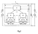
- the test current path contains several series-connected diodes 13, current sensors 12 and MOSFETs 14 which each have a driver circuit 10 is assigned. Between the control unit and the driver circuits are bidirectional potential separating Arranged communication links. Will the driver circuits not activated by the control unit via the communication links this the gate-source voltage of the mosfet below its threshold voltage. All MOSFETs are in this state during the positive half cycle of the Voltage drop between points A and B high impedance. The in the mosfets Integrated diodes prevent reverse voltage at the transistors. During the negative half-wave of the voltage drop, the diodes 13 generally block the test current flow. An executed according to Fig. 1 arrangement can therefore only for a unidirectional Test current flow can be used. Canceling shows that possibly further serially connected components for increasing the dielectric strength are necessary.
- a connection of the circuit breaker becomes the effective value of this voltage drop subjected to a threshold evaluation by the control unit. Is the voltage drop less than, for example, 30 percent of the rated network voltage can do so be assumed that the supply section of network 3 is fed. In In this case, there is no short circuit in the network 5 and the circuit breaker can be switched on.
- the Control unit in the first step over several periods of the fundamental network oscillation To sample the voltage drop across the circuit breaker, the average RMS value form this voltage drop, store this value and the time of the lead angle before the voltage maximum at the end of this step.
- control unit in the second Step all drivers 10 at the same time the signal for setting the defined test resistor value activate.
- the desired resistance of the drain-source channel is set.
- Thenomprüfwiderstand results here from the sum of all arranged in series drain-source channel resistances.
- the value of the test resistor is, for example, around 3kOhm, which is well above the line impedance. At an operating voltage of 15 kV eff, this results in a current limitation to 7 A. Without resistance, a short-circuit current of 45kA might occur.
- the control unit 8 will drive the drivers until the end of the test period and integrate the current at the sensor 9 over the test period.
- test period duration It is proposed a time within a half-wave of the fundamental network oscillation set, advantageously with a lead angle of> 0 degrees and Turned on ⁇ 90 degrees before the voltage maximum and in the subsequent natural Current zero crossing is turned off.
- the influence of the capacitive charging current of the network to be tested for the test result with such a long test duration becomes sufficiently small.
- the turn-off currents are at the end of the test period at such a fixed test period very small, since anyway in this time the process the natural current reversal of the fundamental wave occurs. Notable inductive Abschaltüberschreiben will not arise so first and it can Measures for its suppression be saved.
- the control unit in the third step is the Current integral with a stored average RMS value of the Compare voltage drop dependent threshold.
- the influence of the height of Mains voltage on the measurement result Current integral is not with overhead line networks negligible. At higher voltage will be at a constant set test resistance and otherwise the same network conditions a higher Set test current and thus a higher current integral over the test period.
- the network 5 is classified as short-circuited and the switching on of the circuit breaker 6 prevents.
- FIG. 2 shows the basic structure of the semiconductor test resistor 7 in bipolar design.
- the illustration corresponds to that according to FIG. 1, but the diodes 13 have become the same replaced by MOSFETs 15.
- MOSFETs 15 These will be analog MOSFET 14 in the negative Half-wave of the voltage drop across the semiconductor test resistor is effective. So can the Test period can also be performed in the negative half-wave, if this is the case in exceptional cases should be required.
- When used in three-phase networks is for each Phase of the network requires a separate semiconductor test resistor. It is in a the three phases a bipolar executed semiconductor test resistor necessary be. In the other two, the unipolar version is sufficient. There will be three exams successively necessary to discriminate against all the different network errors can. In two phases, a test period is initiated at the same time.
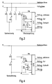
- Fig. 3 shows an operating rail B and a test rail P.
- On the operating rail B is usually at 16.7 Hz overhead line networks an effective voltage of 15 kV.
- the feed branch via the switches S2 and S3 connected to the operating rail B.
- the circuit breaker S3 is triggered in the event of a short circuit or overload, then that the feed branch is no longer supplied by this switchgear.
- a test rail P Parallel to the operating rail B is a test rail P, to which an electrical Test power from the operating rail for testing for short circuit over the Switch S5, the controllable semiconductor test resistor PW, as well as the switch S4 can be applied.
- the semiconductor test resistor is in the illustrated case with a transistor T1 connected antiserially to the diode D1 constructed with integrated freewheeling diode, which can be controlled by a control unit STE is.
- the illustrated current sensor SE1 and the voltage tap on the Transistor provides the control unit with the necessary values for controlling the resistance ready. Not shown in Figure 1 which is necessary to achieve the dielectric strength Series formwork of several elements consisting of D1, T1 and SE1.
- the Control unit STE contains corresponding potential-free driver circuits for driving the semiconductor transistor elements in the resistance region.
- the switches S2, S4, S5 are in normal operation and during the entire test run closed.
- a prerequisite for the start of the test run is the tripped or disconnected circuit breaker S3.
- the switch S1 is first switched on in order to connect the feed branch to the test rail.
- the semiconductor resistor T1 is still high impedance.
- test activate the driver circuit contained in the control unit is activated, which controls the semiconductor resistor (T1) for a test period and synchronized with the voltage curve on the test resistor to a defined resistance value.
- the test current flowing through the test resistor is detected via the current measurement SE1 and fed to the control unit STE.
- the current measured values are integrated by the control unit over the entire test period.
- This current integral is compared for evaluation with a threshold value proportional to the magnitude of the voltage rms value of the mains voltage. If the threshold value is exceeded, the test result is negative.
- the control unit sets the output "Test bad”. The switch S1 is turned off. The affected feed branch remains de-energized and the line test is available again for all feed branches for further tests.
- Fig. 4 shows the possibility of decentralized arrangement. It will be in each feed branch a semiconductor test resistor PW is provided. Compared to the central arrangement can the entire test track assembly and the Streckenprüfschaltfeld omitted. Simultaneous testing of multiple branches shortens supply interruption times essential. The availability of the test in the overall switchgear will be raised.
- switches S2 and S3 are closed and the semiconductor test resistor PW is high impedance.
- the semiconductor test resistor is in the illustrated case with a antiserial to the diode D1 interconnected transistor T1 built with integrated freewheeling diode, which of a control unit STE is controlled.
- the illustrated current sensor SE1 and the Voltage tap across the transistor provides the control unit with the control of the Resistance necessitates values. Not shown in Figure 2 is the achievement the dielectric strength necessary series formwork consisting of several elements from D1, T1 and SE1.
- the control unit STE contains corresponding potential-free Driver circuits for driving the semiconductor transistor elements in Resistance range.
- the switch S2 is closed during normal operation and during the entire test run.
- a prerequisite for the start of the test run is the triggered or deactivated Circuit breaker S3.
- the semiconductor resistor T1 is still high impedance.
- the semiconductor resistor (T1) By one of Control unit STE supplied start signal "check activate” is the in the control unit driver circuit activated, the semiconductor resistor (T1) a Test period long and synchronized with the voltage curve at the test resistor regulated to a defined resistance value.
- the flowing over the test resistor Test current is detected by the current measurement SE1 and fed to the control unit STE.
- the current readings are taken over the entire test period by the control unit integrated.
- This current integral becomes an evaluation of the magnitude of the voltage RMS value compared to the mains voltage proportional threshold. When exceeded of the threshold, the test result is negative.
- the control unit sets the output "exam bad". The affected feed branch remains de-energized.
Landscapes
- Engineering & Computer Science (AREA)
- Mechanical Engineering (AREA)
- Physics & Mathematics (AREA)
- General Physics & Mathematics (AREA)
- Emergency Protection Circuit Devices (AREA)
- Electric Propulsion And Braking For Vehicles (AREA)
- Testing Of Short-Circuits, Discontinuities, Leakage, Or Incorrect Line Connections (AREA)
Priority Applications (3)
| Application Number | Priority Date | Filing Date | Title |
|---|---|---|---|
| AT04005599T ATE305862T1 (de) | 2004-03-09 | 2004-03-09 | Verfahren zur erkennung von kurzschlüssen auf ausgeschalteten leitungsabzweigen von elektrischen wechsel- oder drehstromnetzen, insbesondere auf leitungsabzweigen zur versorgung von eisenbahnstrecken |
| EP04005599A EP1577150B1 (fr) | 2004-03-09 | 2004-03-09 | Dispositif pour la détection de court-circuits dans des lignes d' alimentation de courant alternatif déconnectées, en particulier dans des lignes pour alimentation électrique de reseaux ferroviaires |
| DE502004000087T DE502004000087D1 (de) | 2004-03-09 | 2004-03-09 | Verfahren zur Erkennung von Kurzschlüssen auf ausgeschalteten Leitungsabzweigen von elektrischen Wechsel- oder Drehstromnetzen, insbesondere auf Leitungsabzweigen zur Versorgung von Eisenbahnstrecken |
Applications Claiming Priority (1)
| Application Number | Priority Date | Filing Date | Title |
|---|---|---|---|
| EP04005599A EP1577150B1 (fr) | 2004-03-09 | 2004-03-09 | Dispositif pour la détection de court-circuits dans des lignes d' alimentation de courant alternatif déconnectées, en particulier dans des lignes pour alimentation électrique de reseaux ferroviaires |
Publications (2)
| Publication Number | Publication Date |
|---|---|
| EP1577150A1 true EP1577150A1 (fr) | 2005-09-21 |
| EP1577150B1 EP1577150B1 (fr) | 2005-10-05 |
Family
ID=34833590
Family Applications (1)
| Application Number | Title | Priority Date | Filing Date |
|---|---|---|---|
| EP04005599A Expired - Lifetime EP1577150B1 (fr) | 2004-03-09 | 2004-03-09 | Dispositif pour la détection de court-circuits dans des lignes d' alimentation de courant alternatif déconnectées, en particulier dans des lignes pour alimentation électrique de reseaux ferroviaires |
Country Status (3)
| Country | Link |
|---|---|
| EP (1) | EP1577150B1 (fr) |
| AT (1) | ATE305862T1 (fr) |
| DE (1) | DE502004000087D1 (fr) |
Cited By (4)
| Publication number | Priority date | Publication date | Assignee | Title |
|---|---|---|---|---|
| CN103124063A (zh) * | 2012-07-13 | 2013-05-29 | 中电普瑞科技有限公司 | 一种压比可变的避雷器过压保护装置和实现方法 |
| EP3012642A1 (fr) * | 2014-09-26 | 2016-04-27 | Siemens Aktiengesellschaft | Procédé et système de localisation de panne en cas de court-circuit le long d'une section d'alimentation d'énergie a plusieurs conducteurs |
| EP1949516B2 (fr) † | 2005-10-27 | 2017-08-23 | S & C Electric Company | Procede et appareil de fermeture d'essai de circuit a sensibilisation de courant d'appel |
| CN114523885A (zh) * | 2022-03-03 | 2022-05-24 | 中车青岛四方机车车辆股份有限公司 | 一种高压供电回路保护系统、保护方法及车辆 |
Citations (2)
| Publication number | Priority date | Publication date | Assignee | Title |
|---|---|---|---|---|
| EP0555946A2 (fr) * | 1992-02-14 | 1993-08-18 | Elpro Aktiengesellschaft Berlin - Industrieelektronik und Anlagenbau - | Dispositif de test de ligne pour réseaux de traction, notamment de chemins de fer à voie normale |
| EP0563695A2 (fr) * | 1992-03-31 | 1993-10-06 | Siemens Aktiengesellschaft | Procédé et dispositif pour déterminer des court-circuits dans des branches de réseaux électriques |
-
2004
- 2004-03-09 AT AT04005599T patent/ATE305862T1/de not_active IP Right Cessation
- 2004-03-09 DE DE502004000087T patent/DE502004000087D1/de not_active Expired - Lifetime
- 2004-03-09 EP EP04005599A patent/EP1577150B1/fr not_active Expired - Lifetime
Patent Citations (2)
| Publication number | Priority date | Publication date | Assignee | Title |
|---|---|---|---|---|
| EP0555946A2 (fr) * | 1992-02-14 | 1993-08-18 | Elpro Aktiengesellschaft Berlin - Industrieelektronik und Anlagenbau - | Dispositif de test de ligne pour réseaux de traction, notamment de chemins de fer à voie normale |
| EP0563695A2 (fr) * | 1992-03-31 | 1993-10-06 | Siemens Aktiengesellschaft | Procédé et dispositif pour déterminer des court-circuits dans des branches de réseaux électriques |
Cited By (6)
| Publication number | Priority date | Publication date | Assignee | Title |
|---|---|---|---|---|
| EP1949516B2 (fr) † | 2005-10-27 | 2017-08-23 | S & C Electric Company | Procede et appareil de fermeture d'essai de circuit a sensibilisation de courant d'appel |
| CN103124063A (zh) * | 2012-07-13 | 2013-05-29 | 中电普瑞科技有限公司 | 一种压比可变的避雷器过压保护装置和实现方法 |
| CN103124063B (zh) * | 2012-07-13 | 2015-05-13 | 中电普瑞科技有限公司 | 一种压比可变的避雷器过压保护装置和实现方法 |
| EP3012642A1 (fr) * | 2014-09-26 | 2016-04-27 | Siemens Aktiengesellschaft | Procédé et système de localisation de panne en cas de court-circuit le long d'une section d'alimentation d'énergie a plusieurs conducteurs |
| CN114523885A (zh) * | 2022-03-03 | 2022-05-24 | 中车青岛四方机车车辆股份有限公司 | 一种高压供电回路保护系统、保护方法及车辆 |
| CN114523885B (zh) * | 2022-03-03 | 2024-05-17 | 中车青岛四方机车车辆股份有限公司 | 一种高压供电回路保护系统、保护方法及车辆 |
Also Published As
| Publication number | Publication date |
|---|---|
| EP1577150B1 (fr) | 2005-10-05 |
| DE502004000087D1 (de) | 2005-12-01 |
| ATE305862T1 (de) | 2005-10-15 |
Similar Documents
| Publication | Publication Date | Title |
|---|---|---|
| EP3379725A1 (fr) | Procédé de commande d'un commutateur à courant continu, commutateur à courant continu et système de tension continue | |
| EP0805538A2 (fr) | Protection contre surintensité et contre les courts-circuits | |
| DE102012109012B4 (de) | Schaltungsanordnung für ein Solarkraftwerk mit einer Gleichspannungsquelle für eine Offsetspannung | |
| EP0890220B1 (fr) | Appareil de commutation electronique de derivation | |
| DE102017101451A1 (de) | Niederspannungs-Schutzschaltgerät | |
| DE102011055626A1 (de) | Phasentrennung bei eps-systemen | |
| EP2242665B1 (fr) | Alimentation en énergie électrique d'auxiliaires dans un véhicule sur rails | |
| DE102012024728A1 (de) | Verfahren und Vorrichtung zur Überwachung einer elektrischen Anlage auf einen Rückstrom | |
| EP1577150B1 (fr) | Dispositif pour la détection de court-circuits dans des lignes d' alimentation de courant alternatif déconnectées, en particulier dans des lignes pour alimentation électrique de reseaux ferroviaires | |
| DE102016212211B4 (de) | Kurzschlusserkennung | |
| EP4631769A1 (fr) | Procédé de fonctionnement d'un dispositif d'alimentation électrique, dispositif de commande de coupure et dispositif d'alimentation électrique | |
| EP2347491B1 (fr) | Dispositif pour alimenter un réseau de consommateurs en énergie électrique fournie par un réseau d'alimentation | |
| EP0571423B1 (fr) | Circuit de sous-station a redresseur pour alimentation en courant continu de chemins de fer electriques, et procede | |
| WO2005060061A2 (fr) | Dispositif pour controler un etage final de puissance | |
| DE102019134212A1 (de) | Fahrzeug mit Energiespeichermodul | |
| DE102011004328B4 (de) | Verfahren zum Überbrücken eines Submoduls eines modularen Mehrstufenumrichters | |
| EP3262664A1 (fr) | Procédé permettant de modifier le nombre de spires actives d'un enroulement de régulation dans une installation électrique et installation électrique munie d'un enroulement de régulation | |
| EP1453174A1 (fr) | Méthode et appareil pour detecter des court-circuits dans des branches d'un reseau d'alimentation des sections de voie ferrée | |
| EP2648328A2 (fr) | Protection d'un convertisseur de courant avec circuit intermédiaire contre les dommages causés par la contre-tension d'une machine synchrone | |
| EP3417534B1 (fr) | Convertisseur modulaire multiniveaux | |
| WO2020260673A1 (fr) | Commutateur de puissance destiné à des courants continus | |
| DE102012109283A1 (de) | Stromrichter mit Zusatzschaltung, sowie Verfahren zum Betreiben eines Stromrichters | |
| DE202020101512U1 (de) | Steuereinheit für eine Aufzugsanlage | |
| LU505556B1 (de) | Elektronischer Schalter | |
| DE102022211580B4 (de) | Verfahren zur Ansteuerung von topologischen Schaltern einer Halbbrücke in einem Leistungsmodul eines Inverters |
Legal Events
| Date | Code | Title | Description |
|---|---|---|---|
| GRAP | Despatch of communication of intention to grant a patent |
Free format text: ORIGINAL CODE: EPIDOSNIGR1 |
|
| GRAS | Grant fee paid |
Free format text: ORIGINAL CODE: EPIDOSNIGR3 |
|
| PUAI | Public reference made under article 153(3) epc to a published international application that has entered the european phase |
Free format text: ORIGINAL CODE: 0009012 |
|
| GRAA | (expected) grant |
Free format text: ORIGINAL CODE: 0009210 |
|
| 17P | Request for examination filed |
Effective date: 20041013 |
|
| AK | Designated contracting states |
Kind code of ref document: A1 Designated state(s): AT BE BG CH CY CZ DE DK EE ES FI FR GB GR HU IE IT LI LU MC NL PL PT RO SE SI SK TR |
|
| AX | Request for extension of the european patent |
Extension state: AL LT LV MK |
|
| AK | Designated contracting states |
Kind code of ref document: B1 Designated state(s): AT BE BG CH CY CZ DE DK EE ES FI FR GB GR HU IE IT LI LU MC NL PL PT RO SE SI SK TR |
|
| AX | Request for extension of the european patent |
Extension state: AL LT LV MK |
|
| PG25 | Lapsed in a contracting state [announced via postgrant information from national office to epo] |
Ref country code: IT Free format text: LAPSE BECAUSE OF FAILURE TO SUBMIT A TRANSLATION OF THE DESCRIPTION OR TO PAY THE FEE WITHIN THE PRESCRIBED TIME-LIMIT;WARNING: LAPSES OF ITALIAN PATENTS WITH EFFECTIVE DATE BEFORE 2007 MAY HAVE OCCURRED AT ANY TIME BEFORE 2007. THE CORRECT EFFECTIVE DATE MAY BE DIFFERENT FROM THE ONE RECORDED. Effective date: 20051005 Ref country code: SK Free format text: LAPSE BECAUSE OF FAILURE TO SUBMIT A TRANSLATION OF THE DESCRIPTION OR TO PAY THE FEE WITHIN THE PRESCRIBED TIME-LIMIT Effective date: 20051005 Ref country code: FI Free format text: LAPSE BECAUSE OF FAILURE TO SUBMIT A TRANSLATION OF THE DESCRIPTION OR TO PAY THE FEE WITHIN THE PRESCRIBED TIME-LIMIT Effective date: 20051005 Ref country code: IE Free format text: LAPSE BECAUSE OF FAILURE TO SUBMIT A TRANSLATION OF THE DESCRIPTION OR TO PAY THE FEE WITHIN THE PRESCRIBED TIME-LIMIT Effective date: 20051005 Ref country code: CZ Free format text: LAPSE BECAUSE OF FAILURE TO SUBMIT A TRANSLATION OF THE DESCRIPTION OR TO PAY THE FEE WITHIN THE PRESCRIBED TIME-LIMIT Effective date: 20051005 Ref country code: GB Free format text: LAPSE BECAUSE OF FAILURE TO SUBMIT A TRANSLATION OF THE DESCRIPTION OR TO PAY THE FEE WITHIN THE PRESCRIBED TIME-LIMIT Effective date: 20051005 Ref country code: NL Free format text: LAPSE BECAUSE OF FAILURE TO SUBMIT A TRANSLATION OF THE DESCRIPTION OR TO PAY THE FEE WITHIN THE PRESCRIBED TIME-LIMIT Effective date: 20051005 Ref country code: PL Free format text: LAPSE BECAUSE OF FAILURE TO SUBMIT A TRANSLATION OF THE DESCRIPTION OR TO PAY THE FEE WITHIN THE PRESCRIBED TIME-LIMIT Effective date: 20051005 Ref country code: SI Free format text: LAPSE BECAUSE OF FAILURE TO SUBMIT A TRANSLATION OF THE DESCRIPTION OR TO PAY THE FEE WITHIN THE PRESCRIBED TIME-LIMIT Effective date: 20051005 |
|
| REG | Reference to a national code |
Ref country code: GB Ref legal event code: FG4D Free format text: NOT ENGLISH |
|
| REG | Reference to a national code |
Ref country code: CH Ref legal event code: EP |
|
| REG | Reference to a national code |
Ref country code: IE Ref legal event code: FG4D Free format text: LANGUAGE OF EP DOCUMENT: GERMAN |
|
| REF | Corresponds to: |
Ref document number: 502004000087 Country of ref document: DE Date of ref document: 20051201 Kind code of ref document: P |
|
| REG | Reference to a national code |
Ref country code: SE Ref legal event code: TRGR |
|
| PG25 | Lapsed in a contracting state [announced via postgrant information from national office to epo] |
Ref country code: BG Free format text: LAPSE BECAUSE OF FAILURE TO SUBMIT A TRANSLATION OF THE DESCRIPTION OR TO PAY THE FEE WITHIN THE PRESCRIBED TIME-LIMIT Effective date: 20060105 Ref country code: DK Free format text: LAPSE BECAUSE OF FAILURE TO SUBMIT A TRANSLATION OF THE DESCRIPTION OR TO PAY THE FEE WITHIN THE PRESCRIBED TIME-LIMIT Effective date: 20060105 Ref country code: GR Free format text: LAPSE BECAUSE OF FAILURE TO SUBMIT A TRANSLATION OF THE DESCRIPTION OR TO PAY THE FEE WITHIN THE PRESCRIBED TIME-LIMIT Effective date: 20060105 |
|
| PG25 | Lapsed in a contracting state [announced via postgrant information from national office to epo] |
Ref country code: ES Free format text: LAPSE BECAUSE OF FAILURE TO SUBMIT A TRANSLATION OF THE DESCRIPTION OR TO PAY THE FEE WITHIN THE PRESCRIBED TIME-LIMIT Effective date: 20060116 |
|
| NLV1 | Nl: lapsed or annulled due to failure to fulfill the requirements of art. 29p and 29m of the patents act | ||
| PG25 | Lapsed in a contracting state [announced via postgrant information from national office to epo] |
Ref country code: LU Free format text: LAPSE BECAUSE OF NON-PAYMENT OF DUE FEES Effective date: 20060331 Ref country code: MC Free format text: LAPSE BECAUSE OF NON-PAYMENT OF DUE FEES Effective date: 20060331 Ref country code: BE Free format text: LAPSE BECAUSE OF NON-PAYMENT OF DUE FEES Effective date: 20060331 |
|
| PG25 | Lapsed in a contracting state [announced via postgrant information from national office to epo] |
Ref country code: HU Free format text: LAPSE BECAUSE OF FAILURE TO SUBMIT A TRANSLATION OF THE DESCRIPTION OR TO PAY THE FEE WITHIN THE PRESCRIBED TIME-LIMIT Effective date: 20060406 |
|
| GBV | Gb: ep patent (uk) treated as always having been void in accordance with gb section 77(7)/1977 [no translation filed] |
Effective date: 20051005 |
|
| REG | Reference to a national code |
Ref country code: IE Ref legal event code: FD4D |
|
| AKX | Designation fees paid |
Designated state(s): AT BE BG CH CY CZ DE DK EE ES FI FR GB GR HU IE IT LI LU MC NL PL PT RO SE SI SK TR |
|
| PLBE | No opposition filed within time limit |
Free format text: ORIGINAL CODE: 0009261 |
|
| STAA | Information on the status of an ep patent application or granted ep patent |
Free format text: STATUS: NO OPPOSITION FILED WITHIN TIME LIMIT |
|
| PGFP | Annual fee paid to national office [announced via postgrant information from national office to epo] |
Ref country code: AT Payment date: 20060830 Year of fee payment: 3 |
|
| 26N | No opposition filed |
Effective date: 20060706 |
|
| PG25 | Lapsed in a contracting state [announced via postgrant information from national office to epo] |
Ref country code: FR Free format text: LAPSE BECAUSE OF FAILURE TO SUBMIT A TRANSLATION OF THE DESCRIPTION OR TO PAY THE FEE WITHIN THE PRESCRIBED TIME-LIMIT Effective date: 20061020 |
|
| EN | Fr: translation not filed | ||
| PG25 | Lapsed in a contracting state [announced via postgrant information from national office to epo] |
Ref country code: AT Free format text: LAPSE BECAUSE OF NON-PAYMENT OF DUE FEES Effective date: 20070309 |
|
| BERE | Be: lapsed |
Owner name: VA TECH SAT GMBH & CO Effective date: 20060331 |
|
| PG25 | Lapsed in a contracting state [announced via postgrant information from national office to epo] |
Ref country code: EE Free format text: LAPSE BECAUSE OF FAILURE TO SUBMIT A TRANSLATION OF THE DESCRIPTION OR TO PAY THE FEE WITHIN THE PRESCRIBED TIME-LIMIT Effective date: 20051005 |
|
| PG25 | Lapsed in a contracting state [announced via postgrant information from national office to epo] |
Ref country code: TR Free format text: LAPSE BECAUSE OF FAILURE TO SUBMIT A TRANSLATION OF THE DESCRIPTION OR TO PAY THE FEE WITHIN THE PRESCRIBED TIME-LIMIT Effective date: 20051005 |
|
| PG25 | Lapsed in a contracting state [announced via postgrant information from national office to epo] |
Ref country code: RO Free format text: LAPSE BECAUSE OF FAILURE TO SUBMIT A TRANSLATION OF THE DESCRIPTION OR TO PAY THE FEE WITHIN THE PRESCRIBED TIME-LIMIT Effective date: 20051005 |
|
| REG | Reference to a national code |
Ref country code: CH Ref legal event code: PL |
|
| PG25 | Lapsed in a contracting state [announced via postgrant information from national office to epo] |
Ref country code: CY Free format text: LAPSE BECAUSE OF FAILURE TO SUBMIT A TRANSLATION OF THE DESCRIPTION OR TO PAY THE FEE WITHIN THE PRESCRIBED TIME-LIMIT Effective date: 20051005 Ref country code: FR Free format text: LAPSE BECAUSE OF FAILURE TO SUBMIT A TRANSLATION OF THE DESCRIPTION OR TO PAY THE FEE WITHIN THE PRESCRIBED TIME-LIMIT Effective date: 20051005 |
|
| PG25 | Lapsed in a contracting state [announced via postgrant information from national office to epo] |
Ref country code: LI Free format text: LAPSE BECAUSE OF NON-PAYMENT OF DUE FEES Effective date: 20080331 Ref country code: CH Free format text: LAPSE BECAUSE OF NON-PAYMENT OF DUE FEES Effective date: 20080331 |
|
| PGFP | Annual fee paid to national office [announced via postgrant information from national office to epo] |
Ref country code: SE Payment date: 20100309 Year of fee payment: 7 |
|
| REG | Reference to a national code |
Ref country code: DE Ref legal event code: R081 Ref document number: 502004000087 Country of ref document: DE Owner name: SIEMENS AKTIENGESELLSCHAFT, DE Free format text: FORMER OWNER: VA TECH SAT GMBH & CO., WIEN, AT Effective date: 20110223 |
|
| PG25 | Lapsed in a contracting state [announced via postgrant information from national office to epo] |
Ref country code: PT Free format text: LAPSE BECAUSE OF FAILURE TO SUBMIT A TRANSLATION OF THE DESCRIPTION OR TO PAY THE FEE WITHIN THE PRESCRIBED TIME-LIMIT Effective date: 20051005 |
|
| REG | Reference to a national code |
Ref country code: SE Ref legal event code: EUG |
|
| PG25 | Lapsed in a contracting state [announced via postgrant information from national office to epo] |
Ref country code: DE Free format text: LAPSE BECAUSE OF NON-PAYMENT OF DUE FEES Effective date: 20111001 |
|
| REG | Reference to a national code |
Ref country code: DE Ref legal event code: R084 Ref document number: 502004000087 Country of ref document: DE Effective date: 20130110 |
|
| PG25 | Lapsed in a contracting state [announced via postgrant information from national office to epo] |
Ref country code: SE Free format text: LAPSE BECAUSE OF NON-PAYMENT OF DUE FEES Effective date: 20110310 |
|
| PGFP | Annual fee paid to national office [announced via postgrant information from national office to epo] |
Ref country code: DE Payment date: 20180518 Year of fee payment: 15 |
|
| REG | Reference to a national code |
Ref country code: DE Ref legal event code: R119 Ref document number: 502004000087 Country of ref document: DE |
|
| PG25 | Lapsed in a contracting state [announced via postgrant information from national office to epo] |
Ref country code: DE Free format text: LAPSE BECAUSE OF NON-PAYMENT OF DUE FEES Effective date: 20191001 |