EP1577158B1 - Fahrzeugsitzkissen, und Herstellungsverfahren - Google Patents
Fahrzeugsitzkissen, und Herstellungsverfahren Download PDFInfo
- Publication number
- EP1577158B1 EP1577158B1 EP04425188A EP04425188A EP1577158B1 EP 1577158 B1 EP1577158 B1 EP 1577158B1 EP 04425188 A EP04425188 A EP 04425188A EP 04425188 A EP04425188 A EP 04425188A EP 1577158 B1 EP1577158 B1 EP 1577158B1
- Authority
- EP
- European Patent Office
- Prior art keywords
- cushion
- reference plane
- plane
- contact pressures
- millimetres
- Prior art date
- Legal status (The legal status is an assumption and is not a legal conclusion. Google has not performed a legal analysis and makes no representation as to the accuracy of the status listed.)
- Expired - Lifetime
Links
- 238000000034 method Methods 0.000 title claims description 17
- 238000009826 distribution Methods 0.000 claims abstract description 12
- 239000000463 material Substances 0.000 claims abstract description 12
- 230000002093 peripheral effect Effects 0.000 claims abstract description 7
- 230000000284 resting effect Effects 0.000 claims description 2
- 230000037396 body weight Effects 0.000 abstract 1
- 239000013589 supplement Substances 0.000 description 3
- 230000000295 complement effect Effects 0.000 description 2
- 229920005830 Polyurethane Foam Polymers 0.000 description 1
- 230000004308 accommodation Effects 0.000 description 1
- 230000015572 biosynthetic process Effects 0.000 description 1
- 210000000988 bone and bone Anatomy 0.000 description 1
- 239000006261 foam material Substances 0.000 description 1
- 230000000670 limiting effect Effects 0.000 description 1
- 238000005259 measurement Methods 0.000 description 1
- 230000036961 partial effect Effects 0.000 description 1
- 239000011496 polyurethane foam Substances 0.000 description 1
- 230000002829 reductive effect Effects 0.000 description 1
- 230000002441 reversible effect Effects 0.000 description 1
Images


Classifications
-
- B—PERFORMING OPERATIONS; TRANSPORTING
- B60—VEHICLES IN GENERAL
- B60N—SEATS SPECIALLY ADAPTED FOR VEHICLES; VEHICLE PASSENGER ACCOMMODATION NOT OTHERWISE PROVIDED FOR
- B60N2/00—Seats specially adapted for vehicles; Arrangement or mounting of seats in vehicles
- B60N2/70—Upholstery springs ; Upholstery
- B60N2/7017—Upholstery springs ; Upholstery characterised by the manufacturing process; manufacturing upholstery or upholstery springs not otherwise provided for
-
- B—PERFORMING OPERATIONS; TRANSPORTING
- B60—VEHICLES IN GENERAL
- B60N—SEATS SPECIALLY ADAPTED FOR VEHICLES; VEHICLE PASSENGER ACCOMMODATION NOT OTHERWISE PROVIDED FOR
- B60N2/00—Seats specially adapted for vehicles; Arrangement or mounting of seats in vehicles
- B60N2/64—Back-rests or cushions
- B60N2/643—Back-rests or cushions shape of the back-rests
-
- B—PERFORMING OPERATIONS; TRANSPORTING
- B60—VEHICLES IN GENERAL
- B60N—SEATS SPECIALLY ADAPTED FOR VEHICLES; VEHICLE PASSENGER ACCOMMODATION NOT OTHERWISE PROVIDED FOR
- B60N2/00—Seats specially adapted for vehicles; Arrangement or mounting of seats in vehicles
- B60N2/64—Back-rests or cushions
- B60N2/646—Back-rests or cushions shape of the cushion
-
- B—PERFORMING OPERATIONS; TRANSPORTING
- B60—VEHICLES IN GENERAL
- B60N—SEATS SPECIALLY ADAPTED FOR VEHICLES; VEHICLE PASSENGER ACCOMMODATION NOT OTHERWISE PROVIDED FOR
- B60N2/00—Seats specially adapted for vehicles; Arrangement or mounting of seats in vehicles
- B60N2/70—Upholstery springs ; Upholstery
Definitions
- the present invention relates to a vehicle seat cushion, and to a relevant method of forming said seat cushion.
- cushions or padding are used, both on the backrests and seat portions of the seats, which are relatively thick perpendicularly to the supporting surface, so as to absorb stress in the supporting surface contact regions and attenuate as far as possible any aching feeling caused by contact pressure distribution peaks, particularly over relatively long journeys.
- the cushions of known seats of the above type are unsatisfactory by being relatively bulky, and, particularly as regards the seat portions, by occupying practically all the space between the floor of the vehicle and the user seating surface.
- the US-A-4 718 727 discloses a removable and reversible seat supplement for any kind of chairs, which includes a seat cushion and/or backrest, generally concave on one side and convex on the other side.
- the seat supplement presents intermediate areas having on one side a projection with height increasing stepwise, and on the opposite side a depression with a depth increasing complementary.
- the seat supplement can be reversed by the user according to its size or builds.
- the US-A-3 749 442 discloses another seat assembly having a removable or portable base adapted to be mounted on a chair or like.
- the assembly comprises also two complementary seat elements supported thereon for individual yieldingly universal tilting movement to accommodate to different positions of a user's body.
- the seat elements have recesses or apertures for receiving the ischial tuberosity bones of the user, and the back of the seat has a localized recess for partial reception of the lumbar portion of the user's backbone.
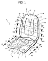
- Number 1 in Figure 1 indicates as a whole a seat (shown partly) of a vehicle (not shown).
- the terms “forwards”, “rearwards”, “front”, “rear”, “bottom”, “top”, “side”, “horizontal”, “vertical”, etc.. are used with reference to the normal accommodation position of the driver or passengers of the vehicle (as shown in Figure 1 ), and with reference to the longitudinal travelling direction of the vehicle.
- Seat 1 comprises a seat portion 3 and a backrest 4, which in turn comprise respective cushions 5, 6 fitted to respective frames (not shown).
- Cushions 5, 6 have a vertical plane P of symmetry ( Figures 4 to 11 ) parallel to the longitudinal travelling direction of the vehicle, comprise upholstered padding made of foam material, and define respective surfaces 7, 8 facing the user, in use, and terminating laterally with respective edges 9, 10, which project upwards and forwards respectively to laterally retain the user as the vehicle is moving.
- Surfaces 7, 8 are shaped symmetrically with respect to plane P, and comprise respective intermediate areas 11, 12 coincident with the regions in which roughly 70% of the weight of the user's body is discharged in use; and respective peripheral areas 13, 14, which are adjacent to areas 11, 12, are subjected, in use, to the remaining 30% of the user's weight, and comprise respective lateral regions 15, 16 connected to edges 9, 10. More specifically, area 13 also comprises a central region 17 interposed between two front end branches 18 of area 11, which correspond to the regions contacting the user's legs.
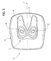
- areas 11, 12 project with respect to areas 13, 14, and are preferably shaped according to the following method from the shape of a standard reference seat 20, of which a plan view of the seat portion 23 only is shown in Figure 3 .
- the seat portion and backrest of reference seat 20 comprise respective supporting planes A and B, which are perpendicular to the plane P of symmetry of the seat, and are defined using as an anthropometric reference the body of a manikin, indicated 21 in Figure 2 , as specified in SAE Standard J826b of January 1974, and classified 95 percentile (i.e. at the top end, in terms of anthropometric dimensions, of 95% of the population).
- plane A slopes upwards and forwards by an angle D of 15° to 25° with respect to a horizontal axis X lying in plane P, and is located at a distance F of 100 millimetres from point H. More specifically, the selected angle D is inversely proportional to the vertical distance, measured as specified in SAE Standard J1100 of June 1984 and not shown in Figure 2 , between point H and the heel 22 of manikin 21.
- Plane B slopes upwards and rearwards by an angle M of 25° with respect to a vertical axis Z lying in plane P, and is located at a distance R of 130 millimetres from point H.
- a contact pressure distribution is determined at the design stage as a reference to establish the relief of areas 11, 12 with respect to planes A, B.
- the contact pressure distribution may be determined by applying a load equal to that of a user's body in the seated position and resting on planes A and B, e.g. by means of manikin 21, and then determining the contact pressures; or may be determined by determining the contact pressures on planes A and B of a sample group of users, and then calculating an average of the findings; or may be determined theoretically on the basis of desired user comfort considerations.
- the height of the padding material on planes A and B is directly proportional to the contact pressure findings, with a proportionality constant selected as a function of the stiffness of the padding material, and of the desired pressure level on seat 1, i.e. depending on whether "racing" or "comfort” performance is intended.
- a proportionality constant selected as a function of the stiffness of the padding material, and of the desired pressure level on seat 1, i.e. depending on whether "racing" or "comfort” performance is intended.
- a proportionality constant of roughly 0.5 g/cm2/mm is preferably selected.
- Number 23 in Figure 3 indicates the seat portion of reference seat 20, on which is shown an example of the distribution of contact pressure levels that can be determined on plane A.
- Contact with manikin 21 mostly occurs in a U-shaped region 24 defined by a perimeter 25, outside which contact pressure is relatively low; and pressure increases gradually towards two intermediate areas 26 symmetrical with respect to plane P and corresponding to the regions supporting the ischial tuberosities of the manikin.
- region 24 coincides, in plan view, with area 11 of seat 1, the outer profile of area 11 rises gradually to two tips ( Figure 1 ), corresponding to areas 26, in proportion to the pressure determined.
- padding material is also added on plane A outside perimeter 25 in proportion to the pressure determined, so that peripheral area 13 does not coincide with plane A.
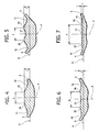
- Figures 4 to 11 show sections illustrating in more detail the shape of cushions 5, 6. More specifically, Figure 4 shows a section of seat portion 3 along a plane IV-IV (see also Figure 2 ) perpendicular to the X axis and defining a plane containing point H; and Figures 5 to 7 show sections along planes V-V, VI-VI and VII-VII, also perpendicular to the X axis and separated forwards from plane IV-IV by 100, 200 and 300 millimetres respectively.
- Figure 8 shows a section of backrest 4 along a plane VIII-VIII perpendicular to the Z axis and defining a plane containing point H; and Figures 9 to 11 show sections along planes IX-IX, X-X and XI-XI, also perpendicular to the Z axis and separated upwards from plane VIII-VIII by 100, 200 and 300 millimetres respectively.
- surfaces 7, 8 comprise respective central depressions 31, 32 located at plane P, elongated along plane P, and separating respective pairs of lateral portions 35, 36 of areas 11, 12, and therefore said tips.
- surfaces 7, 8 are sectioned in planes perpendicular to plane P and intersecting depressions 31, 32, in particular along said planes V-V, VI-VI, X-X and XI-XI
- the outer profiles of surfaces 7, 8 comprise: respective concave central portions 37, 38 defining depressions 31, 32; respective pairs of convex lateral portions 39, 40 connected to portions 37, 38, located on opposite sides of relative depression 31, 32, and defining portions 35, 36; and respective pairs of concave lateral portions 41, 42 connected to portions 39, 40 and defining regions 15, 16 of areas 13, 14.
- the peaks of portions 39 are separated by a distance K ranging between 120 and 225 millimetres, and are separated from plane A by a distance J ranging between 0 and 100 millimetres, depending on the position of the section plane along the X axis.
- the peaks of portions 40 are separated by a distance T ranging between 100 and 200 millimetres, and are separated from plane B by a distance U ranging between 0 and 60 millimetres, depending on the position of the section plane along the Z axis.
- seat 1 has padding material on planes A and B, which means the amount of padding material in the bottom portion of seat portion 3 and in the rear portion of backrest 4 may be reduced to reduce the size of the seat.
- Areas 11 and 12 are relatively easy to shape, by simply determining the contact pressure distributions at the design stage - either on the basis of test measurements using a manikin, or using a sample group of users, or theoretically - and by applying straightforward calculations to calculate the amount of padding material to be added on planes A and B, and therefore the profile of areas 11, 12.
Landscapes
- Engineering & Computer Science (AREA)
- Aviation & Aerospace Engineering (AREA)
- Transportation (AREA)
- Mechanical Engineering (AREA)
- Manufacturing & Machinery (AREA)
- Mattresses And Other Support Structures For Chairs And Beds (AREA)
- Automobile Manufacture Line, Endless Track Vehicle, Trailer (AREA)
- Seats For Vehicles (AREA)
Claims (17)
- Verfahren zum Bilden eines Fahrzeugsitzkissens (5, 6), wobei das Sitzkissen eine Stützfläche (7, 8) aufweist, umfassend:- Einen Mittelbereich (11, 12), an dem ein Großteil des Gewichtes des Körpers des Benützers bei Verwendung ruht;- Einen peripheren Bereich (13, 14) benachbart zu dem Mittelbereich (11, 12), und an welchem der Rest des Gewichtes des Körpers des Benutzers bei Verwendung ruht;wobei der Mittelbereich (11, 12) mit Bezug auf den peripheren Bereich (13, 14) vorspringt;
wobei das Verfahren dadurch gekennzeichnet ist, dass es die Schritte umfasst:- Definieren einer Referenzebene (A, B), senkrecht zur vertikalen Symmetrieebene (P) des Kissens (5, 6);- Bestimmen einer Verteilung von Kontaktdrücken an der Referenzebene (A, B) durch einen Körper in einer sitzenden Position und ruhend an der Referenzebene (A, B);- Bereitstellen einer Menge an Polsterungsmaterial an der Referenzebene (A, B) auf eine Höhe, die abhängig ist von den bestimmten Kontaktdrücken. - Verfahren nach Anspruch 1, dadurch gekennzeichnet, dass die Höhe des Polsterungsmaterials, welches an der Referenzebene (A, B) bereitgestellt wird direkt proportional zu den bestimmten Kontaktdrücken ist.
- Verfahren nach Anspruch 2, dadurch gekennzeichnet, dass die Proportionalitätskonstante zwischen der Höhe und den Kontaktdrücken gewählt ist als eine Funktion der Steife des Polsterungsmaterials.
- Verfahren nach einem der Ansprüche 1 bis 3, dadurch gekennzeichnet, dass die Verteilung der Kontaktdrücke bestimmt wird durch die Positionierung eines Dummies (21) an der Referenzebene (A, B), mit einer Last gleich zu jener die bei Verwendung durch einen Benutzer ausgeübt wird, mittels Bestimmung der Kontaktdrücke.
- Verfahren nach einem der Ansprüche 1 bis 3, dadurch gekennzeichnet, dass die Verteilung von Kontaktdrücken bestimmt wird durch bestimmen der Kontaktdrücke an der Referenzebene (A, B) einer Benutzerprobengruppe und durch errechnen eines Durchschnittes der Ermittlungen.
- Verfahren nach einem der Ansprüche 1 bis 3, dadurch gekennzeichnet, dass die Verteilung von Kontaktdrücken theoretisch bestimmt wird basierend auf gewünschtem Komfort.
- Verfahren nach einem der Ansprüche 1 bis 6, dadurch gekennzeichnet, dass der Schritt des Definierens der Referenzebene (A, B) Handlungen umfasst von:- Definieren eines Referenzkörpers (21);- Auswählen eines Referenzpunktes (H) an dem Referenzkörper (21) in einer sitzenden Positionierung;- Positionieren der Referenzebene (A, B) bei einer Neigung (D, M) und einem vorbestimmten Abstand (F, R) mit Bezug auf den ausgewählten Referenzpunkt (H).
- Verfahren nach Anspruch 7, dadurch gekennzeichnet, dass der Referenzpunkt (H) ausgewählt ist am Gelenk zwischen der Hüfte und den Beinen eines Standardreferenzdummies (21).
- Verfahren nach Anspruch 8, dadurch gekennzeichnet, dass beim Ausbilden eines Kissens (5) eines Sitzabschnittes (3) die Referenzebene (A) aufwärtig und vorwärtig geneigt vorliegt bei einem Winkel (D) von 15° bis 25° mit Bezug auf eine Horizontalachse (X) und befindlich ist bei einem Abstand (F) von 100 Millimetern bezüglich des Referenzpunktes (H); und beim bilden eines Kissens (6) einer Rückenlehne (4) die Referenzebene (D) aufwärtig und rückwärtig geneigt ist um einen Winkel (M) von 25° mit Bezug auf eine vertikal Achse (Z), und befindlich ist bei einem Abstand (R) von 130 Millimetern mit Bezug auf den Referenzpunkt (H).
- Fahrzeugsitzkissen (5, 6), gekennzeichnet durch die Ausbildung gemäß dem Verfahren nach einem der vorangegangenen Ansprüche, wobei der Mittelbereich (11, 12) Scheitelbereiche (26) umfasst, entsprechend den Scheiteln der bestimmten Kontaktdrücke; wobei das vorspringen des Mittelbereiches (11, 12) kontinuierlich hin zu den Scheitelbereichen (26) zunimmt.
- Kissen nach Anspruch 10, dadurch gekennzeichnet, dass es eine vertikale Symmetrieebene (P) umfasst; und dadurch, dass die Stützfläche (7, 8) eine mittlere Absenkung (31, 32) an der vertikalen Symmetrieebene (P) umfasst.
- Kissen nach Anspruch 11, dadurch gekennzeichnet, dass die mittlere Absenkung (31, 32) länglich entlang der vertikalen Symmetrieebene (P) ist; wobei der Mittelbereich (11, 12) zwei vorspringende Lateralabschnitte (35, 36) umfasst, separiert durch die mittlere Absenkung (31, 32).
- Kissen nach Anspruch 12, dadurch gekennzeichnet, dass mittels Sektionierung der Stützfläche (7, 8) entlang Schnittebenen senkrecht zur vertikalen Symmetrieebene (P) und die mittlere Absenkung (31, 32) schneidend das äußere Profil der Stützfläche umfasst:- einen konkaven Mittelabschnitt (37, 38), die mittlere Absenkung (31, 32) definierend;- ein Paar von konvexen Lateralabschnitten (39, 40), verbunden bezüglich des konkaven Mittelabschnittes (37, 38), befindlich an entgegengesetzten Seiten der mittleren Absenkung (31, 32) und die vorspringenden Lateralabschnitte (35, 36) definierend;- ein Paar von konkaven Lateralabschnitten (41, 42), verbunden bezüglich der konvexen Lateralabschnitte (39, 40), und jeweils Lateralabschnitte (15, 16) des peripheren Bereiches (13, 14) definierend.
- Kissen nach Anspruch 13, dadurch gekennzeichnet, dass es geeignet ist für einen Sitzabschnitt (3) des Sitzes (1); und dadurch, dass der Abstand zwischen den Scheitelbereichen der konvexen Lateralabschnitte (39) in einen Bereich liegt zwischen 120 und 225 Millimetern, und zwar abhängig von dem Ort der Schnittebenen.
- Kissen nach Anspruch 13, dadurch gekennzeichnet, dass es geeignet ist für eine Rückenlehne (4) des Sitzes (1); und dadurch, dass die Entfernung zwischen Scheitelbereichen der konvexen Lateralabschnitte (40) in einem Bereich liegt zwischen 100 und 200 Millimetern, und zwar abhängig von dem Ort der Schnittebenen.
- Kissen nach Anspruch 15, dadurch gekennzeichnet, dass die Scheitelbereiche bei einer Höhe vorliegen in einem Bereich zwischen 0 und 60 Millimetern mit Bezug auf eine erste Idealreferenzebene (B), senkrecht vorliegend bezüglich der vertikalen Symmetrieebene (P); wobei die erste Idealreferenzebene (B) aufwärtig und rückwärtig geneigt ist um einen Winkel (M) von 25° mit Bezug auf eine Vertikalachse (Z), und befindlich ist bei einem Abstand (R) von 130 Millimeter mit Bezug auf das Gelenk (H) zwischen der Hüfte und den Beinen eines Referenzkörpers (21) in einer sitzenden Position.
- Kissen nach Anspruch 14, dadurch gekennzeichnet, dass die Scheitelbereiche bei einer Höhe vorliegen in einem Bereich zwischen 0 und 100 mm mit Bezug auf eine zweite Idealreferenzebene (A), senkrecht vorliegend bezüglich der vertikalen Symmetrieebene (P); wobei die zweite Idealreferenzebene (A) aufwärtig und vorwärtig geneigt ist um einen Winkel (D) von 15° bis 25° mit Bezug auf eine Horizontalachse (X), und befindlich ist bei einer Entfernung oder einem Abstand (F) von 100 Millimeter bezüglich dem Gelenk (H) zwischen der Hüfte und den Beinen eines Referenzkörpers (21) in einer sitzenden Position oder Positionierung.
Priority Applications (3)
| Application Number | Priority Date | Filing Date | Title |
|---|---|---|---|
| EP04425188A EP1577158B1 (de) | 2004-03-17 | 2004-03-17 | Fahrzeugsitzkissen, und Herstellungsverfahren |
| DE602004023049T DE602004023049D1 (de) | 2004-03-17 | 2004-03-17 | Fahrzeugsitzkissen, und Herstellungsverfahren |
| AT04425188T ATE442279T1 (de) | 2004-03-17 | 2004-03-17 | Fahrzeugsitzkissen, und herstellungsverfahren |
Applications Claiming Priority (1)
| Application Number | Priority Date | Filing Date | Title |
|---|---|---|---|
| EP04425188A EP1577158B1 (de) | 2004-03-17 | 2004-03-17 | Fahrzeugsitzkissen, und Herstellungsverfahren |
Publications (2)
| Publication Number | Publication Date |
|---|---|
| EP1577158A1 EP1577158A1 (de) | 2005-09-21 |
| EP1577158B1 true EP1577158B1 (de) | 2009-09-09 |
Family
ID=34833838
Family Applications (1)
| Application Number | Title | Priority Date | Filing Date |
|---|---|---|---|
| EP04425188A Expired - Lifetime EP1577158B1 (de) | 2004-03-17 | 2004-03-17 | Fahrzeugsitzkissen, und Herstellungsverfahren |
Country Status (3)
| Country | Link |
|---|---|
| EP (1) | EP1577158B1 (de) |
| AT (1) | ATE442279T1 (de) |
| DE (1) | DE602004023049D1 (de) |
Families Citing this family (3)
| Publication number | Priority date | Publication date | Assignee | Title |
|---|---|---|---|---|
| FR2974545B1 (fr) * | 2011-04-27 | 2016-08-26 | Soc Nat Des Chemins De Fer Francais S N C F | Siege de vehicule muni d'un renfort permettant l'orientation du bassin afin d'ameliorer le confort du passager |
| DE102011114622A1 (de) | 2011-09-30 | 2013-04-04 | Sitech Sitztechnik Gmbh | Fahrzeugsitz mit aus autoreaktivenGerüststrukturen ausgebildeten Seitenwangen |
| DE102012020049B4 (de) * | 2012-10-12 | 2022-01-27 | Sitech Sitztechnik Gmbh | Kindersitz nach Finray-Prinzip |
Family Cites Families (11)
| Publication number | Priority date | Publication date | Assignee | Title |
|---|---|---|---|---|
| NL98570C (de) * | 1957-02-05 | 1961-07-17 | ||
| US3145054A (en) * | 1962-07-12 | 1964-08-18 | Jr John Sopko | Portable chair seat with a backsupporting pneumatic cushion |
| US3503649A (en) * | 1968-04-01 | 1970-03-31 | Merle E Johnson | Contoured support cushion |
| DE2039121A1 (de) * | 1970-08-06 | 1972-02-10 | Stephan Diehl | Nach Koerpermassen angefertigte Sitzschale und Herstellungsverfahren |
| US3749442A (en) * | 1971-08-30 | 1973-07-31 | J Berg | Seat having relatively adjustable sections |
| US4718727A (en) * | 1984-05-29 | 1988-01-12 | Sheppard Michael B | Reversible seat cushion and backrest |
| IT1241270B (it) * | 1990-06-29 | 1993-12-29 | Fiat Auto Spa | Procedimento per realizzare vaschette di contenimento per cuscini, particolarmente cuscini di sedili per autoveicoli. |
| DE19601974C2 (de) * | 1996-01-20 | 1998-07-02 | Daimler Benz Ag | Verfahren zur Ermittlung des Druckkomforts eines Sitz- und/oder Lehnenpolsters |
| US6713001B1 (en) * | 1997-12-29 | 2004-03-30 | Lear Corporation | Surface imaging method for a vehicle seat |
| DE19850226B4 (de) * | 1998-10-26 | 2006-03-09 | Nadia Chinouda | Orthopädische Sitzauflage |
| DE10148662B4 (de) * | 2001-10-02 | 2006-05-24 | Daimlerchrysler Ag | Verfahren zur quantitativen Ermittlung des dynamischen Sitzkomforts eines Sitzpolsters |
-
2004
- 2004-03-17 AT AT04425188T patent/ATE442279T1/de not_active IP Right Cessation
- 2004-03-17 EP EP04425188A patent/EP1577158B1/de not_active Expired - Lifetime
- 2004-03-17 DE DE602004023049T patent/DE602004023049D1/de not_active Expired - Lifetime
Also Published As
| Publication number | Publication date |
|---|---|
| ATE442279T1 (de) | 2009-09-15 |
| DE602004023049D1 (de) | 2009-10-22 |
| EP1577158A1 (de) | 2005-09-21 |
Similar Documents
| Publication | Publication Date | Title |
|---|---|---|
| JP4442876B2 (ja) | 車両用シート | |
| US8733843B2 (en) | Process for producing a supporting shell for a seat | |
| JP2523149B2 (ja) | 椅子部材 | |
| US4668015A (en) | Chair without a back/a stool | |
| CA2521200A1 (en) | Seat with adjustable support system | |
| US20130113264A1 (en) | Comfortable orthopedic chair for prevention of spinal diseases | |
| EP0786954B1 (de) | Verbesserungen für stühle | |
| JP7482941B2 (ja) | 姿勢保持具 | |
| CN101283866A (zh) | 靠背设有形状记忆海绵的椅子 | |
| EP2353928A1 (de) | Sitz und Rückenlehne für ein Industriefahrzeug | |
| EP1577158B1 (de) | Fahrzeugsitzkissen, und Herstellungsverfahren | |
| EP0153360B1 (de) | Unterstützungsplatte in einem sitz | |
| JP4196744B2 (ja) | 車両用シート | |
| JP2004290605A (ja) | 車両用シートの背凭シート | |
| CA2520267A1 (en) | Tiltable chair accomodating male and female user seating position preferences | |
| KR102574701B1 (ko) | 자세 교정형 의자 | |
| WO2000030501A1 (en) | Rocking chair | |
| CN110856579B (zh) | 就座用坐垫以及椅子用座面 | |
| JPH11253268A (ja) | 車両用シート | |
| JPH11235942A (ja) | 乗合い車両用腰掛け | |
| Lim et al. | The effect of lumbar support prominence on driver's comfort and body pressure distribution | |
| US20250236227A1 (en) | Vehicle seat | |
| JP2024166820A (ja) | 車両用シート | |
| US20070130750A1 (en) | Method of providing a seat back involving the use of a design manikin | |
| JP5510994B2 (ja) | 腰掛 |
Legal Events
| Date | Code | Title | Description |
|---|---|---|---|
| PUAI | Public reference made under article 153(3) epc to a published international application that has entered the european phase |
Free format text: ORIGINAL CODE: 0009012 |
|
| 17P | Request for examination filed |
Effective date: 20041230 |
|
| AK | Designated contracting states |
Kind code of ref document: A1 Designated state(s): AT BE BG CH CY CZ DE DK EE ES FI FR GB GR HU IE IT LI LU MC NL PL PT RO SE SI SK TR |
|
| AX | Request for extension of the european patent |
Extension state: AL LT LV MK |
|
| AKX | Designation fees paid |
Designated state(s): AT BE BG CH CY CZ DE DK EE ES FI FR GB GR HU IE IT LI LU MC NL PL PT RO SE SI SK TR |
|
| GRAP | Despatch of communication of intention to grant a patent |
Free format text: ORIGINAL CODE: EPIDOSNIGR1 |
|
| GRAS | Grant fee paid |
Free format text: ORIGINAL CODE: EPIDOSNIGR3 |
|
| GRAA | (expected) grant |
Free format text: ORIGINAL CODE: 0009210 |
|
| RIN1 | Information on inventor provided before grant (corrected) |
Inventor name: MASOERO, GIORGIO,C/O C.R.F.SOCIETA CONSORTILE PER |
|
| AK | Designated contracting states |
Kind code of ref document: B1 Designated state(s): AT BE BG CH CY CZ DE DK EE ES FI FR GB GR HU IE IT LI LU MC NL PL PT RO SE SI SK TR |
|
| REG | Reference to a national code |
Ref country code: GB Ref legal event code: FG4D |
|
| REG | Reference to a national code |
Ref country code: CH Ref legal event code: EP |
|
| REG | Reference to a national code |
Ref country code: IE Ref legal event code: FG4D |
|
| REF | Corresponds to: |
Ref document number: 602004023049 Country of ref document: DE Date of ref document: 20091022 Kind code of ref document: P |
|
| PG25 | Lapsed in a contracting state [announced via postgrant information from national office to epo] |
Ref country code: SE Free format text: LAPSE BECAUSE OF FAILURE TO SUBMIT A TRANSLATION OF THE DESCRIPTION OR TO PAY THE FEE WITHIN THE PRESCRIBED TIME-LIMIT Effective date: 20090909 Ref country code: FI Free format text: LAPSE BECAUSE OF FAILURE TO SUBMIT A TRANSLATION OF THE DESCRIPTION OR TO PAY THE FEE WITHIN THE PRESCRIBED TIME-LIMIT Effective date: 20090909 |
|
| NLV1 | Nl: lapsed or annulled due to failure to fulfill the requirements of art. 29p and 29m of the patents act | ||
| PG25 | Lapsed in a contracting state [announced via postgrant information from national office to epo] |
Ref country code: PL Free format text: LAPSE BECAUSE OF FAILURE TO SUBMIT A TRANSLATION OF THE DESCRIPTION OR TO PAY THE FEE WITHIN THE PRESCRIBED TIME-LIMIT Effective date: 20090909 Ref country code: NL Free format text: LAPSE BECAUSE OF FAILURE TO SUBMIT A TRANSLATION OF THE DESCRIPTION OR TO PAY THE FEE WITHIN THE PRESCRIBED TIME-LIMIT Effective date: 20090909 Ref country code: SI Free format text: LAPSE BECAUSE OF FAILURE TO SUBMIT A TRANSLATION OF THE DESCRIPTION OR TO PAY THE FEE WITHIN THE PRESCRIBED TIME-LIMIT Effective date: 20090909 |
|
| PG25 | Lapsed in a contracting state [announced via postgrant information from national office to epo] |
Ref country code: CY Free format text: LAPSE BECAUSE OF FAILURE TO SUBMIT A TRANSLATION OF THE DESCRIPTION OR TO PAY THE FEE WITHIN THE PRESCRIBED TIME-LIMIT Effective date: 20090909 |
|
| PG25 | Lapsed in a contracting state [announced via postgrant information from national office to epo] |
Ref country code: RO Free format text: LAPSE BECAUSE OF FAILURE TO SUBMIT A TRANSLATION OF THE DESCRIPTION OR TO PAY THE FEE WITHIN THE PRESCRIBED TIME-LIMIT Effective date: 20090909 Ref country code: ES Free format text: LAPSE BECAUSE OF FAILURE TO SUBMIT A TRANSLATION OF THE DESCRIPTION OR TO PAY THE FEE WITHIN THE PRESCRIBED TIME-LIMIT Effective date: 20091220 Ref country code: PT Free format text: LAPSE BECAUSE OF FAILURE TO SUBMIT A TRANSLATION OF THE DESCRIPTION OR TO PAY THE FEE WITHIN THE PRESCRIBED TIME-LIMIT Effective date: 20100111 Ref country code: CZ Free format text: LAPSE BECAUSE OF FAILURE TO SUBMIT A TRANSLATION OF THE DESCRIPTION OR TO PAY THE FEE WITHIN THE PRESCRIBED TIME-LIMIT Effective date: 20090909 Ref country code: EE Free format text: LAPSE BECAUSE OF FAILURE TO SUBMIT A TRANSLATION OF THE DESCRIPTION OR TO PAY THE FEE WITHIN THE PRESCRIBED TIME-LIMIT Effective date: 20090909 |
|
| PG25 | Lapsed in a contracting state [announced via postgrant information from national office to epo] |
Ref country code: SK Free format text: LAPSE BECAUSE OF FAILURE TO SUBMIT A TRANSLATION OF THE DESCRIPTION OR TO PAY THE FEE WITHIN THE PRESCRIBED TIME-LIMIT Effective date: 20090909 |
|
| PG25 | Lapsed in a contracting state [announced via postgrant information from national office to epo] |
Ref country code: BE Free format text: LAPSE BECAUSE OF FAILURE TO SUBMIT A TRANSLATION OF THE DESCRIPTION OR TO PAY THE FEE WITHIN THE PRESCRIBED TIME-LIMIT Effective date: 20090909 Ref country code: AT Free format text: LAPSE BECAUSE OF FAILURE TO SUBMIT A TRANSLATION OF THE DESCRIPTION OR TO PAY THE FEE WITHIN THE PRESCRIBED TIME-LIMIT Effective date: 20090909 |
|
| PLBE | No opposition filed within time limit |
Free format text: ORIGINAL CODE: 0009261 |
|
| STAA | Information on the status of an ep patent application or granted ep patent |
Free format text: STATUS: NO OPPOSITION FILED WITHIN TIME LIMIT |
|
| PG25 | Lapsed in a contracting state [announced via postgrant information from national office to epo] |
Ref country code: DK Free format text: LAPSE BECAUSE OF FAILURE TO SUBMIT A TRANSLATION OF THE DESCRIPTION OR TO PAY THE FEE WITHIN THE PRESCRIBED TIME-LIMIT Effective date: 20090909 |
|
| 26N | No opposition filed |
Effective date: 20100610 |
|
| PG25 | Lapsed in a contracting state [announced via postgrant information from national office to epo] |
Ref country code: MC Free format text: LAPSE BECAUSE OF NON-PAYMENT OF DUE FEES Effective date: 20100331 Ref country code: GR Free format text: LAPSE BECAUSE OF FAILURE TO SUBMIT A TRANSLATION OF THE DESCRIPTION OR TO PAY THE FEE WITHIN THE PRESCRIBED TIME-LIMIT Effective date: 20091210 |
|
| REG | Reference to a national code |
Ref country code: CH Ref legal event code: PL |
|
| GBPC | Gb: european patent ceased through non-payment of renewal fee |
Effective date: 20100317 |
|
| PG25 | Lapsed in a contracting state [announced via postgrant information from national office to epo] |
Ref country code: IE Free format text: LAPSE BECAUSE OF NON-PAYMENT OF DUE FEES Effective date: 20100317 |
|
| PG25 | Lapsed in a contracting state [announced via postgrant information from national office to epo] |
Ref country code: CH Free format text: LAPSE BECAUSE OF NON-PAYMENT OF DUE FEES Effective date: 20100331 Ref country code: LI Free format text: LAPSE BECAUSE OF NON-PAYMENT OF DUE FEES Effective date: 20100331 |
|
| PG25 | Lapsed in a contracting state [announced via postgrant information from national office to epo] |
Ref country code: GB Free format text: LAPSE BECAUSE OF NON-PAYMENT OF DUE FEES Effective date: 20100317 |
|
| PGFP | Annual fee paid to national office [announced via postgrant information from national office to epo] |
Ref country code: FR Payment date: 20110317 Year of fee payment: 8 |
|
| PGFP | Annual fee paid to national office [announced via postgrant information from national office to epo] |
Ref country code: DE Payment date: 20110309 Year of fee payment: 8 |
|
| PGFP | Annual fee paid to national office [announced via postgrant information from national office to epo] |
Ref country code: IT Payment date: 20110328 Year of fee payment: 8 |
|
| PG25 | Lapsed in a contracting state [announced via postgrant information from national office to epo] |
Ref country code: HU Free format text: LAPSE BECAUSE OF FAILURE TO SUBMIT A TRANSLATION OF THE DESCRIPTION OR TO PAY THE FEE WITHIN THE PRESCRIBED TIME-LIMIT Effective date: 20100310 Ref country code: LU Free format text: LAPSE BECAUSE OF NON-PAYMENT OF DUE FEES Effective date: 20100317 Ref country code: BG Free format text: LAPSE BECAUSE OF FAILURE TO SUBMIT A TRANSLATION OF THE DESCRIPTION OR TO PAY THE FEE WITHIN THE PRESCRIBED TIME-LIMIT Effective date: 20090909 |
|
| PG25 | Lapsed in a contracting state [announced via postgrant information from national office to epo] |
Ref country code: TR Free format text: LAPSE BECAUSE OF FAILURE TO SUBMIT A TRANSLATION OF THE DESCRIPTION OR TO PAY THE FEE WITHIN THE PRESCRIBED TIME-LIMIT Effective date: 20090909 |
|
| REG | Reference to a national code |
Ref country code: FR Ref legal event code: ST Effective date: 20121130 |
|
| REG | Reference to a national code |
Ref country code: DE Ref legal event code: R119 Ref document number: 602004023049 Country of ref document: DE Effective date: 20121002 |
|
| PG25 | Lapsed in a contracting state [announced via postgrant information from national office to epo] |
Ref country code: FR Free format text: LAPSE BECAUSE OF NON-PAYMENT OF DUE FEES Effective date: 20120402 |
|
| PG25 | Lapsed in a contracting state [announced via postgrant information from national office to epo] |
Ref country code: IT Free format text: LAPSE BECAUSE OF NON-PAYMENT OF DUE FEES Effective date: 20120317 |
|
| PG25 | Lapsed in a contracting state [announced via postgrant information from national office to epo] |
Ref country code: DE Free format text: LAPSE BECAUSE OF NON-PAYMENT OF DUE FEES Effective date: 20121002 |