EP1577193A1 - Système de direction du type "steer-by-wire" avec embrayage électroaimant - Google Patents
Système de direction du type "steer-by-wire" avec embrayage électroaimant Download PDFInfo
- Publication number
- EP1577193A1 EP1577193A1 EP05251392A EP05251392A EP1577193A1 EP 1577193 A1 EP1577193 A1 EP 1577193A1 EP 05251392 A EP05251392 A EP 05251392A EP 05251392 A EP05251392 A EP 05251392A EP 1577193 A1 EP1577193 A1 EP 1577193A1
- Authority
- EP
- European Patent Office
- Prior art keywords
- steer
- armature
- rotor
- solenoid coil
- wire system
- Prior art date
- Legal status (The legal status is an assumption and is not a legal conclusion. Google has not performed a legal analysis and makes no representation as to the accuracy of the status listed.)
- Granted
Links
- 230000002441 reversible effect Effects 0.000 claims abstract description 4
- 230000004907 flux Effects 0.000 claims description 9
- 230000007423 decrease Effects 0.000 claims description 2
- 230000002950 deficient Effects 0.000 abstract description 6
- 230000005540 biological transmission Effects 0.000 description 5
- 230000002093 peripheral effect Effects 0.000 description 4
- 238000010276 construction Methods 0.000 description 3
- 239000000463 material Substances 0.000 description 3
- 230000033001 locomotion Effects 0.000 description 2
- 230000007935 neutral effect Effects 0.000 description 2
- 238000005516 engineering process Methods 0.000 description 1
- 239000000696 magnetic material Substances 0.000 description 1
- 230000003252 repetitive effect Effects 0.000 description 1
- 239000007787 solid Substances 0.000 description 1
- 230000000087 stabilizing effect Effects 0.000 description 1
Images




Classifications
-
- B—PERFORMING OPERATIONS; TRANSPORTING
- B62—LAND VEHICLES FOR TRAVELLING OTHERWISE THAN ON RAILS
- B62D—MOTOR VEHICLES; TRAILERS
- B62D5/00—Power-assisted or power-driven steering
- B62D5/001—Mechanical components or aspects of steer-by-wire systems, not otherwise provided for in this maingroup
- B62D5/003—Backup systems, e.g. for manual steering
-
- B—PERFORMING OPERATIONS; TRANSPORTING
- B62—LAND VEHICLES FOR TRAVELLING OTHERWISE THAN ON RAILS
- B62D—MOTOR VEHICLES; TRAILERS
- B62D5/00—Power-assisted or power-driven steering
- B62D5/04—Power-assisted or power-driven steering electrical, e.g. using an electric servo-motor connected to, or forming part of, the steering gear
- B62D5/043—Power-assisted or power-driven steering electrical, e.g. using an electric servo-motor connected to, or forming part of, the steering gear characterised by clutch means between driving element, e.g. motor, and driven element, e.g. steering column or steering gear
- B62D5/0433—Power-assisted or power-driven steering electrical, e.g. using an electric servo-motor connected to, or forming part of, the steering gear characterised by clutch means between driving element, e.g. motor, and driven element, e.g. steering column or steering gear the clutch being of on-off type
-
- F—MECHANICAL ENGINEERING; LIGHTING; HEATING; WEAPONS; BLASTING
- F16—ENGINEERING ELEMENTS AND UNITS; GENERAL MEASURES FOR PRODUCING AND MAINTAINING EFFECTIVE FUNCTIONING OF MACHINES OR INSTALLATIONS; THERMAL INSULATION IN GENERAL
- F16D—COUPLINGS FOR TRANSMITTING ROTATION; CLUTCHES; BRAKES
- F16D27/00—Magnetically- or electrically- actuated clutches; Control or electric circuits therefor
- F16D27/10—Magnetically- or electrically- actuated clutches; Control or electric circuits therefor with an electromagnet not rotating with a clutching member, i.e. without collecting rings
- F16D27/108—Magnetically- or electrically- actuated clutches; Control or electric circuits therefor with an electromagnet not rotating with a clutching member, i.e. without collecting rings with axially movable clutching members
- F16D27/112—Magnetically- or electrically- actuated clutches; Control or electric circuits therefor with an electromagnet not rotating with a clutching member, i.e. without collecting rings with axially movable clutching members with flat friction surfaces, e.g. discs
-
- F—MECHANICAL ENGINEERING; LIGHTING; HEATING; WEAPONS; BLASTING
- F16—ENGINEERING ELEMENTS AND UNITS; GENERAL MEASURES FOR PRODUCING AND MAINTAINING EFFECTIVE FUNCTIONING OF MACHINES OR INSTALLATIONS; THERMAL INSULATION IN GENERAL
- F16D—COUPLINGS FOR TRANSMITTING ROTATION; CLUTCHES; BRAKES
- F16D28/00—Electrically-actuated clutches
-
- F—MECHANICAL ENGINEERING; LIGHTING; HEATING; WEAPONS; BLASTING
- F16—ENGINEERING ELEMENTS AND UNITS; GENERAL MEASURES FOR PRODUCING AND MAINTAINING EFFECTIVE FUNCTIONING OF MACHINES OR INSTALLATIONS; THERMAL INSULATION IN GENERAL
- F16D—COUPLINGS FOR TRANSMITTING ROTATION; CLUTCHES; BRAKES
- F16D41/00—Freewheels or freewheel clutches
- F16D41/06—Freewheels or freewheel clutches with intermediate wedging coupling members between an inner and an outer surface
- F16D41/064—Freewheels or freewheel clutches with intermediate wedging coupling members between an inner and an outer surface the intermediate members wedging by rolling and having a circular cross-section, e.g. balls
- F16D41/066—Freewheels or freewheel clutches with intermediate wedging coupling members between an inner and an outer surface the intermediate members wedging by rolling and having a circular cross-section, e.g. balls all members having the same size and only one of the two surfaces being cylindrical
- F16D41/067—Freewheels or freewheel clutches with intermediate wedging coupling members between an inner and an outer surface the intermediate members wedging by rolling and having a circular cross-section, e.g. balls all members having the same size and only one of the two surfaces being cylindrical and the members being distributed by a separate cage encircling the axis of rotation
-
- F—MECHANICAL ENGINEERING; LIGHTING; HEATING; WEAPONS; BLASTING
- F16—ENGINEERING ELEMENTS AND UNITS; GENERAL MEASURES FOR PRODUCING AND MAINTAINING EFFECTIVE FUNCTIONING OF MACHINES OR INSTALLATIONS; THERMAL INSULATION IN GENERAL
- F16D—COUPLINGS FOR TRANSMITTING ROTATION; CLUTCHES; BRAKES
- F16D41/00—Freewheels or freewheel clutches
- F16D41/06—Freewheels or freewheel clutches with intermediate wedging coupling members between an inner and an outer surface
- F16D41/08—Freewheels or freewheel clutches with intermediate wedging coupling members between an inner and an outer surface with provision for altering the freewheeling action
- F16D41/086—Freewheels or freewheel clutches with intermediate wedging coupling members between an inner and an outer surface with provision for altering the freewheeling action the intermediate members being of circular cross-section and wedging by rolling
- F16D41/088—Freewheels or freewheel clutches with intermediate wedging coupling members between an inner and an outer surface with provision for altering the freewheeling action the intermediate members being of circular cross-section and wedging by rolling the intermediate members being of only one size and wedging by a movement not having an axial component, between inner and outer races, one of which is cylindrical
Definitions
- This invention relates to a steer-by-wire system, and more particularly it relates to a fail-safe mechanism for steer-by-wire systems, so designed that when a defective condition develops in a steer-by-wire system, a shaft connected directly to the steering wheel is connected to a shaft connected to the steering gear, so as to make direct steering by the steering wheel possible.
- Steer-by-wire systems replace a system in which the steering wheel and the steering gear of an automobile are not mechanically connected, and are adapted to control the steer angle by rotating a motor through electric signals. Since steer-by-wire systems, which dispense with steering shaft and the like for connecting the steering wheel and steering gear, increase the degree of freedom of car interior layout and allow automatic control of road wheel steer angle according to the vehicle speed; thus, steer-by-wire systems are expected to improve safety travel and motion performance of vehicles.
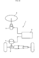
- Fig. 14 schematically illustrates a steer-by-wire system 1.
- a steering wheel 2 and a steering gear 3 are not mechanically connected, and instead the steer angle of the steering gear 3 is operated through a steer actuator 5 controlled by a controller 6 according to the steer angle of the steering wheel 2, and a reaction simulator 4 imparts a steer reaction controlled by the controller 6 to the steering wheel 2.
- Japanese Patent Application Laid-Open under No. 2001-30-1639 discloses a fail-safe mechanism therefor, in which the steering wheel and the steering gear are connected by a solenoid clutch to allow direct steering by the steering wheel.
- An object of the invention is to provide a steer-by-wire system adapted to be less influenced by a failure in the electric system, to reduce power consumption, to be compacted in size as a whole, and to reduce the drag torque during dragging.
- a steer-by-wire system of the invention comprises a first shaft connected to a steering wheel, a first motor imparting a steer reaction to the first shaft, a second shaft connected to a steering gear, a second motor for imparting steer force to the second shaft, and a clutch installed between the first and second shafts for switching the first and second shafts between a connected position and a non-connected position, the arrangement being such that normally said clutch is held in the disengaged state and steering is effected by the first motor imparting a steer reaction to the first shaft and the second motor imparting a steer force to the second shaft, wherein the clutch 10 is composed of a mechanical clutch section, and a solenoid coil controlling said mechanical clutch section, and is a reverse actuation type clutch such that when the solenoid coil is in the energized state, the mechanical clutch section is in the disengaged state, while when the solenoid coil is in the de-energized state, the mechanical clutch section is in the engaged state.
- the clutch may have the following elements:
- the clutch may have the following element:
- the steer-by-wire system of the invention comprises a mechanical clutch disposed between inner and outer rings, with engaging elements for engagement, and a solenoid coil, the arrangement being such that when the solenoid coil is energized, the mechanical clutch section is placed in the disengaged state, while when the solenoid coil is de-energized, the mechanical clutch section is placed in the engaged state. Therefore, the mechanical clutch section which works as a practical fail-safe mechanism can be easily controlled by controlling the energized state of the solenoid coil, and since the mechanical clutch section is engaged when the solenoid coil is de-energized, it is possible to prevent occurrence of steer incapability due to a defective condition of the electric system, thus improving the safety of the steer-by-wire system.
- the solenoid coil is used to control the engaged state of the mechanical clutch section, and it is possible to reduce the power consumption as compared with the solenoid clutch which directly transmits power.
- the portion which makes the steering wheel and the steering gear engaged or disengaged is the mechanical clutch section, and since the mechanical clutch section has a large allowable transmission torque as compared with friction type clutches including solenoid clutches, the clutch section can be compacted in size.
- Fig. 1 shows the entire arrangement of a steer-by-wire system 1
- Figs. 2 - 7 show a first embodiment
- Figs. 8 - 13 show a second embodiment.
- a steering wheel 2 and a steering gear 3 are not mechanically connected and instead it is arranged that the steer angle of the steering gear 3 is operated through a steer actuator 5 controlled by a controller 6 according to the steer angle of the steering wheel 2, and a steer reaction controlled by the controller 6 is imparted to the steering wheel 2 by a reaction simulator 4.
- a reaction simulator 4 This is basically the same as in the prior art in Fig. 14.
- the reference character 7 denotes road wheels. Attached to a first shaft 8 directly connected to the steering wheel 2 is a first motor 4 for transmitting the steer reaction to the first shaft 8.
- a clutch 10 is disposed between the first and second shafts 8 and 9.
- the clutch 10 is of such construction that it is switched to connect or disconnect the first and second shafts 8 and 9, thus constituting a fail-safe mechanism for the steer-by-wire system 1. That is, if a defective condition occurs in the steer-by-wire system 1, the clutch 10 is placed in the engaged state to allow direct steer by the steering wheel 2.
- the clutch 10 is a mechanical clutch in which engaging elements disposed between the inner and outer rings engage each other to establish an engaged state, and is of such construction that when the solenoid coil is energized, the mechanical clutch is placed in the disengaged state, while when the solenoid coil is de-energized, the mechanical clutch is placed in the engaged state.
- the concrete arrangement of the clutch 10 is as follows.
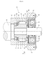
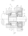
- the clutch 10 as shown in Figs. 2 and 4, has an inner ring 11 and an outer ring 12 which are supported for relative rotation.
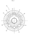
- the inner peripheral surface of the outer ring 12 is a cylindrical surface 20, and the outer peripheral surface of the inner ring 11 is formed with cam surfaces 19 which cooperate with the cylindrical surface 20 of the outer ring 12 to define wedge spaces therebetween.
- a cage 13 Interposed between the cam surface 19 of the inner ring 11 and the cylindrical surface 20 of the outer ring 12 is a cage 13 held for rotation relative to the inner ring 11.
- the cage 13 has the same number of pockets 21 as the number of cam surfaces 19 in the inner ring 11, with a roller 14 incorporated in each pocket 21.
- the cage 13 is elastically supported circumferentially by a switch spring 18.
- the switch spring 18 consists of an annular section and a pair of substantially radially extending engaging sections.
- the annular section is mounted in a peripheral groove formed in the end of the inner ring 11, while the engaging sections project outward through holes extending radially of the inner ring 11 to engage notches in the cage 13.
- the cage 13 is usually held in a neutral position (Fig. 3) where the rollers 14 do not simultaneously contact the cam surface 19 of the inner ring 11 and the cylindrical surface 20 of the outer ring 12. Therefore, the inner and outer rings 11 and 12 are in a relatively rotatable state. As shown in Fig.
- the inner ring 11 is serration- or spline-joined, for torque transmission, to a first rotary shaft 22 connected to either one of the first and second shafts 8 and 9 of the steer-by-wire system 100.
- the outer ring 12 is serration- or spline-joined, for torque transmission, to a second rotary shaft 23 connected to the other of the first and second shafts 8 and 9 of the steer-by-wire system 100. Therefore, the connected or disconnected state of the first and second shafts 8 and 9 of the steer-by-wire system 100 can be determined by controlling the engaged or disengaged state of the clutch 10.
- a rotor 16 is attached to the rotary shaft 22.
- the rotor 16 in this case, is supported through a roller bearing, and the rotary shaft 22 and the rotor 16 are relatively rotatable.
- the rotor 16 is fitted to the outer ring 12 through a rotor guide 27 made of nonmagnetic material.
- One end of the rotor 16 is formed with a radially outwardly bent projection, which is inserted into a notch in the outer ring 12 to serve as a whirl-stop for both.
- Interposed between the rotor 16 and the outer ring 12 are an armature 15 and a switching plate 26.
- the armature 15 is in such a relation that it is not movable relative to the cage 13 except axially. That is, a portion of the cage 13 which extends axially is inserted into a through hole in the armature 15, whereby the armature 15 and the cage 13 are not relatively rotatable but are relatively movable only axially.
- an elastic member 28 Interposed between the armature 15 and the end surface of the inner ring 11 is an elastic member 28 for urging the armature 15 against the switching plate 26.
- the movement of the armature 15 to the switching plate 26 is restricted by a stop ring 30 mounted on the rotary shaft 22.
- An elastic member 29 is interposed between the switching plate 26 and the rotor 16.
- the switching plate 26, rotor 16 and rotor guide 27 are in such a relation that they are relatively movable only axially. That is, the switching plate 26 has a radial projection, which is engaged in an axial groove formed in the inner peripheral surface of the rotor guide 27.
- the rotor 16 has a recess for receiving the solenoid coil 17 and is provided with a slit 25 axially extending therethrough from the recess to the switching plate 26.
- the solenoid coil 17 is fixed to the case 24 which belongs to the stationary system. There is a clearance between the rotor 16 and the solenoid coil 17, and both are relatively rotatable.
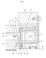
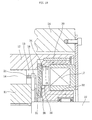
- Figs. 2 and 4 show the solenoid coil 17 in the energized state. That is, when the solenoid coil 17 is energized, the switching plate 26 is attracted to the rotor 16. At this time, by the action of the elastic member 28, the armature 15 is moved to a position where it contacts the stop ring 30. The stop ring 30 plays the role of preventing the armature 15 from contacting the switching plate 26 when the latter is attracted to the rotor 16. This ensures that the armature 15 does not contact the outer ring 12 (or the member deprived of freedom of rotation relative to the outer ring 12), that the rollers 14 are held in the neutral position by the action of the switch spring 18 (Fig. 3), and that the inner and outer rings 11 and 12 maintain the disconnected state.
- Figs. 5 and 6 show the solenoid coil 17 in the de-energized state.
- the switching plate 26 is separated from the rotor 16 and is in frictional contact with the armature 15.
- the rollers 14 are moved to cut into the wedge spaces against the elastic force of the switch spring 17 to establish the connected state of the inner and outer rings 11 and 12.
- setting is made such that the pressing force F 29 of the elastic member 29 is greater than the pressing force F 28 of the elastic member 28 and the armature 15 is pressed to the outer ring 12 for frictional contact therewith, it is possible to increase the friction area to require a smaller force in switching from the disconnected to connected state.
- making the armature 15 of nonmagnetic material makes it less vulnerable to the influence of magnetic flux generated when the solenoid coil 17 is energized, thus stabilizing operability.
- FIG. 8 A second embodiment will now be described with reference to Figs. 8 through 13.
- This embodiment abolishes the switching plate 26 used in the first embodiment described above and adds a permanent magnet 34.
- Substantially the same parts and regions as those in the first embodiment are denoted by the same reference characters and a repetitive description thereof is omitted.
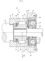
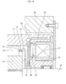
- Figs. 8, 9 and 10 show the disconnected state.
- an armature 31 made of magnetic material is in such a relation that it is movable relative to the cage 13 only axially, as in the case of the armature 15 in the first embodiment.
- a rotor 32 together with a rotor guide 33 of nonmagnetic material is fixed to the outer ring 12, such that the rotor 32 is opposed to the armature 31.
- the rotor 32 has a slit 35 extending therethrough from a recess receiving the solenoid coil 17 to the armature 31, with the permanent magnet 34 fixed in said slit 35.
- the solenoid coil 17 is energized, as shown in broken lines in Fig.
- the magnetic flux of the solenoid coil 17 is produced in a direction opposite to the magnetic flux (solid line arrow) of the permanent magnet 34 passing through the armature 31.
- the attractive force due to the magnetic flux of the armature 31 is cancelled, the armature 31 is separated from the rotor 32 by the action of the elastic member 36.
- Figs. 11, 12 and 13 show a connected state.
- the solenoid coil 17 is in the de-energized state, the magnetic flux generated by the permanent magnet 34 passes through the armature 31, as shown by solid arrows in Fig. 13.
- the armature 31 is attracted to the rotor 32, and the armature 31 and rotor 32 are frictionally contacted; thus, the clutch is engaged.
- the first and second embodiments use a reverse action type clutch as a fail-safe mechanism for steer-by-wire systems, such that the energization of the solenoid coil results in the disengaged state and the de-energization of the solenoid coil results in the engaged state.
- a reverse action type clutch as a fail-safe mechanism for steer-by-wire systems, such that the energization of the solenoid coil results in the disengaged state and the de-energization of the solenoid coil results in the engaged state.
- the outer ring is formed with a cylindrical surface; and the inner ring is formed with cam surfaces; however, reversely, the inner ring may be formed with a cylindrical surface while forming the outer ring with cam surfaces.
Landscapes
- Engineering & Computer Science (AREA)
- General Engineering & Computer Science (AREA)
- Mechanical Engineering (AREA)
- Chemical & Material Sciences (AREA)
- Combustion & Propulsion (AREA)
- Transportation (AREA)
- Physics & Mathematics (AREA)
- Electromagnetism (AREA)
- Power Steering Mechanism (AREA)
Applications Claiming Priority (2)
| Application Number | Priority Date | Filing Date | Title |
|---|---|---|---|
| JP2004076615A JP4347100B2 (ja) | 2004-03-17 | 2004-03-17 | ステアバイワイヤシステム |
| JP2004076615 | 2004-03-17 |
Publications (2)
| Publication Number | Publication Date |
|---|---|
| EP1577193A1 true EP1577193A1 (fr) | 2005-09-21 |
| EP1577193B1 EP1577193B1 (fr) | 2007-10-24 |
Family
ID=34836548
Family Applications (1)
| Application Number | Title | Priority Date | Filing Date |
|---|---|---|---|
| EP05251392A Ceased EP1577193B1 (fr) | 2004-03-17 | 2005-03-08 | Système de direction du type "steer-by-wire" avec embrayage électroaimant |
Country Status (4)
| Country | Link |
|---|---|
| US (1) | US7448464B2 (fr) |
| EP (1) | EP1577193B1 (fr) |
| JP (1) | JP4347100B2 (fr) |
| DE (1) | DE602005002965T2 (fr) |
Cited By (6)
| Publication number | Priority date | Publication date | Assignee | Title |
|---|---|---|---|---|
| EP1792803A1 (fr) | 2005-12-01 | 2007-06-06 | Nissan Motor Co., Ltd. | Appareil de direction |
| CN104995078A (zh) * | 2013-01-11 | 2015-10-21 | 日产自动车株式会社 | 转向控制装置、转向控制方法 |
| CN106164523A (zh) * | 2014-03-27 | 2016-11-23 | Ntn株式会社 | 旋转传递装置 |
| CN106256655A (zh) * | 2015-06-16 | 2016-12-28 | 株式会社捷太格特 | 转向装置 |
| EP3971436A1 (fr) * | 2020-09-17 | 2022-03-23 | Segway Technology Co., Ltd. | Essieu pour un véhicule avec embrayage à roue libre commutable électromagnétique |
| EP4406815A4 (fr) * | 2021-09-22 | 2025-01-15 | NTN Corporation | Système de direction à commande électrique |
Families Citing this family (32)
| Publication number | Priority date | Publication date | Assignee | Title |
|---|---|---|---|---|
| JP4682639B2 (ja) * | 2005-02-15 | 2011-05-11 | 日産自動車株式会社 | 操舵制御装置 |
| JP4625727B2 (ja) * | 2005-06-30 | 2011-02-02 | 日立オートモティブシステムズ株式会社 | 電磁アクチュエータ及びそれを用いたクラッチ機構及び自動車の動力伝達機構 |
| JP4622837B2 (ja) * | 2005-12-09 | 2011-02-02 | トヨタ自動車株式会社 | 車両の操舵装置 |
| JP4876634B2 (ja) * | 2006-03-01 | 2012-02-15 | 日産自動車株式会社 | 車両用操舵制御装置 |
| EP1837267B1 (fr) * | 2006-03-15 | 2013-02-27 | Mazda Motor Corporation | Dispositif de direction pour véhicule |
| US7810605B2 (en) | 2006-12-28 | 2010-10-12 | Nissan Motor Co., Ltd. | Vehicle steering device and control method for vehicle steering device |
| JP4420036B2 (ja) | 2007-02-05 | 2010-02-24 | 日産自動車株式会社 | 車両用操舵制御装置 |
| JP4367520B2 (ja) * | 2007-04-26 | 2009-11-18 | 日産自動車株式会社 | 車両用可変ギヤ比操舵装置 |
| US20100311016A1 (en) * | 2008-01-14 | 2010-12-09 | En Technologies Limited | Steering mechanism |
| JP5124832B2 (ja) * | 2008-01-31 | 2013-01-23 | 本田技研工業株式会社 | 車両の操舵装置 |
| JP2010221758A (ja) * | 2009-03-19 | 2010-10-07 | Nissan Motor Co Ltd | 車両用操舵装置のクラッチ |
| JP5402133B2 (ja) * | 2009-03-19 | 2014-01-29 | 日産自動車株式会社 | 車両用操舵装置のクラッチ |
| JP5589290B2 (ja) * | 2009-03-24 | 2014-09-17 | 日産自動車株式会社 | 車両用操舵装置 |
| DE102010014284B4 (de) * | 2010-04-08 | 2012-03-08 | Deutsches Zentrum für Luft- und Raumfahrt e.V. | Steuereinrichtung |
| US20120031726A1 (en) * | 2010-08-05 | 2012-02-09 | Columbus Mckinnon Corporation | Modular clutch assembly |
| JP5658046B2 (ja) * | 2011-01-21 | 2015-01-21 | Ntn株式会社 | 回転伝達装置 |
| JP6121119B2 (ja) * | 2011-09-26 | 2017-04-26 | Ntn株式会社 | 回転伝達装置 |
| DE102011116264A1 (de) | 2011-10-19 | 2013-04-25 | Rheinmetall Landsysteme Gmbh | In einem Kraftfahrzeug anordbare Vorrichtung mit mindestens einem Aktuator für eine Kraftfahrzeug-Steer-by-Wire-Lenkeinrichtung |
| JP5673630B2 (ja) * | 2012-09-04 | 2015-02-18 | トヨタ自動車株式会社 | 操舵装置 |
| US9478341B2 (en) | 2012-11-12 | 2016-10-25 | Borgwarner Inc. | Solenoid assembly for friction clutch |
| JP2015044479A (ja) * | 2013-08-28 | 2015-03-12 | Ntn株式会社 | 車両用操舵装置 |
| JP6191387B2 (ja) | 2013-08-29 | 2017-09-06 | 株式会社ジェイテクト | 継手構造及び風力発電装置 |
| JP2015189346A (ja) * | 2014-03-28 | 2015-11-02 | Ntn株式会社 | 車両操舵システム用ユニット |
| JP6607371B2 (ja) | 2015-06-16 | 2019-11-20 | 株式会社ジェイテクト | ステアリング装置 |
| JP2017136919A (ja) * | 2016-02-02 | 2017-08-10 | 株式会社ジェイテクト | ステアリング装置 |
| DE102016210956A1 (de) * | 2016-06-20 | 2017-12-21 | Schaeffler Technologies AG & Co. KG | Tretpedalvorrichtung mit Freilaufeinrichtung |
| CN108343686A (zh) * | 2017-01-22 | 2018-07-31 | 上海鸣志电器股份有限公司 | 一种线性离合器 |
| SE544243C2 (en) * | 2018-09-05 | 2022-03-15 | Sentient Ip Ab | Method and device for combined hydraulic and electric power assisted steering |
| KR102055744B1 (ko) * | 2018-11-29 | 2019-12-13 | 김항래 | 드리프팅 전동 보드 |
| CN112960033B (zh) * | 2021-04-21 | 2024-11-05 | 豫北转向系统(新乡)股份有限公司 | 一种用于汽车转向系统的同步离合器 |
| JP7841992B2 (ja) * | 2022-08-30 | 2026-04-07 | Ntn株式会社 | ステアバイワイヤ式操舵システム |
| JP2024033083A (ja) * | 2022-08-30 | 2024-03-13 | Ntn株式会社 | ステアバイワイヤ式操舵システム |
Citations (3)
| Publication number | Priority date | Publication date | Assignee | Title |
|---|---|---|---|---|
| EP0447626A2 (fr) * | 1990-03-23 | 1991-09-25 | Dr.Ing.h.c. F. Porsche Aktiengesellschaft | Déclencheur pour une direction cybernétique |
| JP2003090356A (ja) * | 2001-09-17 | 2003-03-28 | Ntn Corp | 回転伝達装置 |
| US20040182670A1 (en) * | 2002-07-02 | 2004-09-23 | Hiromi Nojiri | Rotation transmission device |
Family Cites Families (5)
| Publication number | Priority date | Publication date | Assignee | Title |
|---|---|---|---|---|
| US6231448B1 (en) * | 1997-05-16 | 2001-05-15 | Mitsuba Corporation | Power steering system |
| JP4419114B2 (ja) * | 2000-11-14 | 2010-02-24 | 株式会社ジェイテクト | 車両用操舵装置 |
| US6817457B2 (en) * | 2001-07-26 | 2004-11-16 | Ntn Corporation | Two-way roller clutch with torque limiting feature |
| JP4107471B2 (ja) * | 2001-11-19 | 2008-06-25 | 三菱電機株式会社 | 車両用操舵装置 |
| US20050155809A1 (en) * | 2004-01-20 | 2005-07-21 | Krzesicki Richard M. | Mechanical clutch coupling back-up for electric steering system |
-
2004
- 2004-03-17 JP JP2004076615A patent/JP4347100B2/ja not_active Expired - Fee Related
-
2005
- 2005-03-08 DE DE602005002965T patent/DE602005002965T2/de not_active Expired - Lifetime
- 2005-03-08 EP EP05251392A patent/EP1577193B1/fr not_active Ceased
- 2005-03-11 US US11/077,357 patent/US7448464B2/en not_active Expired - Fee Related
Patent Citations (3)
| Publication number | Priority date | Publication date | Assignee | Title |
|---|---|---|---|---|
| EP0447626A2 (fr) * | 1990-03-23 | 1991-09-25 | Dr.Ing.h.c. F. Porsche Aktiengesellschaft | Déclencheur pour une direction cybernétique |
| JP2003090356A (ja) * | 2001-09-17 | 2003-03-28 | Ntn Corp | 回転伝達装置 |
| US20040182670A1 (en) * | 2002-07-02 | 2004-09-23 | Hiromi Nojiri | Rotation transmission device |
Non-Patent Citations (1)
| Title |
|---|
| PATENT ABSTRACTS OF JAPAN vol. 2003, no. 07 3 July 2003 (2003-07-03) * |
Cited By (12)
| Publication number | Priority date | Publication date | Assignee | Title |
|---|---|---|---|---|
| EP1792803A1 (fr) | 2005-12-01 | 2007-06-06 | Nissan Motor Co., Ltd. | Appareil de direction |
| CN104995078A (zh) * | 2013-01-11 | 2015-10-21 | 日产自动车株式会社 | 转向控制装置、转向控制方法 |
| CN104995078B (zh) * | 2013-01-11 | 2017-06-09 | 日产自动车株式会社 | 转向控制装置、转向控制方法 |
| CN106164523A (zh) * | 2014-03-27 | 2016-11-23 | Ntn株式会社 | 旋转传递装置 |
| CN106164523B (zh) * | 2014-03-27 | 2018-11-09 | Ntn株式会社 | 旋转传递装置 |
| US10138954B2 (en) | 2014-03-27 | 2018-11-27 | Ntn Corporation | Rotation transmission device |
| CN106256655A (zh) * | 2015-06-16 | 2016-12-28 | 株式会社捷太格特 | 转向装置 |
| EP3109132A1 (fr) * | 2015-06-16 | 2016-12-28 | Jtekt Corporation | Système de direction |
| US9988073B2 (en) | 2015-06-16 | 2018-06-05 | Jtekt Corporation | Steering system |
| EP3971436A1 (fr) * | 2020-09-17 | 2022-03-23 | Segway Technology Co., Ltd. | Essieu pour un véhicule avec embrayage à roue libre commutable électromagnétique |
| US11415184B2 (en) | 2020-09-17 | 2022-08-16 | Segway Technology Co. Ltd. | Axle and vehicle |
| EP4406815A4 (fr) * | 2021-09-22 | 2025-01-15 | NTN Corporation | Système de direction à commande électrique |
Also Published As
| Publication number | Publication date |
|---|---|
| DE602005002965D1 (de) | 2007-12-06 |
| DE602005002965T2 (de) | 2008-08-07 |
| JP2005262969A (ja) | 2005-09-29 |
| EP1577193B1 (fr) | 2007-10-24 |
| JP4347100B2 (ja) | 2009-10-21 |
| US20050205336A1 (en) | 2005-09-22 |
| US7448464B2 (en) | 2008-11-11 |
Similar Documents
| Publication | Publication Date | Title |
|---|---|---|
| US7448464B2 (en) | Steer-by-wire system | |
| CN107444478B (zh) | 用于车辆线控转向系统的控制组件 | |
| CA2919537C (fr) | Embrayage a roue libre selectionnable muni d'une entretoise a induit separe | |
| US6257386B1 (en) | Power cut/connect device | |
| EP3124817B1 (fr) | Dispositif de transmission de rotation | |
| KR101831393B1 (ko) | 전자 액추에이터 | |
| JP2009293759A (ja) | 回転伝達装置 | |
| JP2007315602A (ja) | 電磁操作式ユニット、特にクラッチ/ブレーキ又はロッキング装置 | |
| JP4200853B2 (ja) | 駆動力伝達装置及びそのアンバランス確認方法 | |
| US11519468B2 (en) | Rotating e-clutch assembly providing four operating modes | |
| JP4252392B2 (ja) | クラッチ | |
| JP7696265B2 (ja) | ステアバイワイヤ式操舵装置 | |
| JP4606921B2 (ja) | 回転伝達装置 | |
| JP2000274450A (ja) | 動力断続装置 | |
| JP2008051244A (ja) | 回転伝達装置 | |
| JP2007270986A (ja) | 回転伝達装置 | |
| JP2008032036A (ja) | 回転伝達装置 | |
| JP2007187249A (ja) | 回転伝達装置 | |
| JP2025149113A (ja) | 回転伝達装置 | |
| JP2025082296A (ja) | 双方向電磁クラッチ及びシフト装置 | |
| JP2023157173A (ja) | ステアリング装置 | |
| JP2007270983A (ja) | ステアバイワイヤシステム用回転伝達装置 | |
| JP2008144850A (ja) | 回転伝達装置 | |
| JP2023117695A (ja) | 回転伝達装置及びステアバイワイヤ方式の車両用操舵装置 | |
| EP2290253B1 (fr) | Système de transmission de puissance pour véhicule changeant d'état de transmission de puissance par commande électrique |
Legal Events
| Date | Code | Title | Description |
|---|---|---|---|
| PUAI | Public reference made under article 153(3) epc to a published international application that has entered the european phase |
Free format text: ORIGINAL CODE: 0009012 |
|
| AK | Designated contracting states |
Kind code of ref document: A1 Designated state(s): AT BE BG CH CY CZ DE DK EE ES FI FR GB GR HU IE IS IT LI LT LU MC NL PL PT RO SE SI SK TR |
|
| AX | Request for extension of the european patent |
Extension state: AL BA HR LV MK YU |
|
| 17P | Request for examination filed |
Effective date: 20060208 |
|
| AKX | Designation fees paid |
Designated state(s): DE |
|
| GRAP | Despatch of communication of intention to grant a patent |
Free format text: ORIGINAL CODE: EPIDOSNIGR1 |
|
| GRAS | Grant fee paid |
Free format text: ORIGINAL CODE: EPIDOSNIGR3 |
|
| GRAA | (expected) grant |
Free format text: ORIGINAL CODE: 0009210 |
|
| AK | Designated contracting states |
Kind code of ref document: B1 Designated state(s): DE |
|
| REF | Corresponds to: |
Ref document number: 602005002965 Country of ref document: DE Date of ref document: 20071206 Kind code of ref document: P |
|
| PLBE | No opposition filed within time limit |
Free format text: ORIGINAL CODE: 0009261 |
|
| STAA | Information on the status of an ep patent application or granted ep patent |
Free format text: STATUS: NO OPPOSITION FILED WITHIN TIME LIMIT |
|
| 26N | No opposition filed |
Effective date: 20080725 |
|
| PGFP | Annual fee paid to national office [announced via postgrant information from national office to epo] |
Ref country code: DE Payment date: 20170228 Year of fee payment: 13 |
|
| REG | Reference to a national code |
Ref country code: DE Ref legal event code: R119 Ref document number: 602005002965 Country of ref document: DE |
|
| PG25 | Lapsed in a contracting state [announced via postgrant information from national office to epo] |
Ref country code: DE Free format text: LAPSE BECAUSE OF NON-PAYMENT OF DUE FEES Effective date: 20181002 |