EP1577198A2 - Section de chenille pour véhicule chenillé avec semelle - Google Patents
Section de chenille pour véhicule chenillé avec semelle Download PDFInfo
- Publication number
- EP1577198A2 EP1577198A2 EP05004603A EP05004603A EP1577198A2 EP 1577198 A2 EP1577198 A2 EP 1577198A2 EP 05004603 A EP05004603 A EP 05004603A EP 05004603 A EP05004603 A EP 05004603A EP 1577198 A2 EP1577198 A2 EP 1577198A2
- Authority
- EP
- European Patent Office
- Prior art keywords
- track
- central
- attachment
- plate
- width
- Prior art date
- Legal status (The legal status is an assumption and is not a legal conclusion. Google has not performed a legal analysis and makes no representation as to the accuracy of the status listed.)
- Granted
Links
- 230000007704 transition Effects 0.000 claims description 4
- 230000003993 interaction Effects 0.000 claims description 2
- 230000003014 reinforcing effect Effects 0.000 claims description 2
- 238000012790 confirmation Methods 0.000 claims 1
- 230000001419 dependent effect Effects 0.000 claims 1
- 238000005452 bending Methods 0.000 description 5
- 230000000295 complement effect Effects 0.000 description 3
- 238000013459 approach Methods 0.000 description 2
- 230000015572 biosynthetic process Effects 0.000 description 1
- UQMRAFJOBWOFNS-UHFFFAOYSA-N butyl 2-(2,4-dichlorophenoxy)acetate Chemical compound CCCCOC(=O)COC1=CC=C(Cl)C=C1Cl UQMRAFJOBWOFNS-UHFFFAOYSA-N 0.000 description 1
- 238000009434 installation Methods 0.000 description 1
- 230000002787 reinforcement Effects 0.000 description 1
- 230000003313 weakening effect Effects 0.000 description 1
Images


Classifications
-
- B—PERFORMING OPERATIONS; TRANSPORTING
- B62—LAND VEHICLES FOR TRAVELLING OTHERWISE THAN ON RAILS
- B62D—MOTOR VEHICLES; TRAILERS
- B62D55/00—Endless track vehicles
- B62D55/08—Endless track units; Parts thereof
- B62D55/18—Tracks
- B62D55/26—Ground engaging parts or elements
- B62D55/28—Ground engaging parts or elements detachable
Definitions
- the invention relates to a track chain for a tracked vehicle for a drive plate for a such caterpillar.
- each link plate cross-bolt fastening is bolted to a track of a tracked vehicle by means of several, each a link plate cross-bolt fastening.
- Usual are a total of 4 mounting bolts per drive plate, with two fastening bolts are provided per link plate.
- each drive plate is weakened by the required for the fastening bolts through holes just at or in the immediate vicinity of the cross section, where it is exposed to a maximum bending moment.
- the object of the invention is to provide an improved track chain for a tracked vehicle, as well as an improved disk drive, in which the above-described problem of weakening a heavily loaded cross-section no longer exists or at least significantly mitigated.
- a track for a tracked vehicle solved which is characterized in that at least one chain link of the track a central Attachment means for releasably securing a drive plate, which is within a central, arranged adjacent to a longitudinal center plane of the track Fastening area is located.
- the central mounting area can range up to 75% or up to 50% or up to 25% have a width of the chain link.
- the central attachment means may be through one or two transverse to the longitudinal center plane extending attachment approach (approaches) of one or both link plates of the chain link be formed.
- the central fastening means by a between two Chain link areas of the chain link extending and integrally formed therewith Connection area is formed.
- the central attachment means may be at least one central Mounting opening with internal thread for receiving at least one fastening bolt include.
- the central fastening means in the aforementioned manner by a fastening lug or a connection region is formed, it can be provided that the central fastening means with respect to an operating surface of the track outside the bearing surface of the Chain link along the longitudinal center plane stepped inwardly staggered, with lateral Transition shoulders between the central fastener and the abutment surface a Centering for a complementary trained Zentrianssausformung a Make drive plate.
- the central fastening means by a chain link attached to the chain link, the chain link transversely to the longitudinal center plane spanning Adapter plate is formed.
- the adapter plate can on both sides of the longitudinal center plane in each case at least one lateral Have mounting hole for attachment to the link plates.
- the adapter plate at least one within the central mounting area Has located central mounting opening for mounting the drive plate.
- the at least one central attachment opening of the adapter plate (each) by an internally threaded and with the adapter plate insoluble connected reinforcing sleeve is formed.
- the adapter plate may have a width substantially equal to the width of the chain link equivalent. It can be provided that the adapter plate has a width which until is twice the width of the chain link.
- the adapter plate transversely to the longitudinal center plane substantially is rigid.
- the invention further relates to a drive plate for a crawler according to the invention, wherein the drive plate by a central fastening means for attachment within the central attachment area of the track.
- the central attachment means may comprise at least one attachment opening which may be formed symmetrically to the longitudinal center plane. Preferred is a (single) central Attachment opening provided.
- the drive plate is transverse to the longitudinal center plane elastic.
- the at least one mounting hole as a mounting hole formed with stepped diameters.
- the adapter plate aligned recesses for centering interaction are arranged with bolt heads of mounting bolts of the adapter plate.
- the Staggered central fastening means is staggered, can be provided that at a in the assembled state of the contact surface of the chain link facing the top of Drive plate a complementary to the transition shoulders Zentri mecanicsausformung is formed, which cooperates centering with the transitional shoulders.
- the invention further relates to a tracked vehicle with an inventive Track.
- Figs. 7 and 8 are sectional and plan views show a conventional track plate for a crawler track of a tracked vehicle.
- the known drive plate 1 is fastened with four fastening bolts on a track, the bolts passing through four mounting holes passing through the drive plate 2, 4 grab.
- Each mounting hole has a smaller diameter portion, which serves to receive a stud shaft, and a section of larger diameter, which serves to receive a bolt head. Because the width of the track is only slightly larger than the center distance, i.
- a drive disk 1 as shown in FIGS. 7 and 8, fastened with four fastening bolts on a chain link, which is designed similar to the designated in Fig. 1 and 2 with 104 chain link, wherein the fastening bolts in four Mounting holes corresponding to the mounting holes 20 of the chain link 104th intervention.
- the chain link of the track central fastening means for releasably securing a drive plate in Difference to the known fasteners (corresponding to the mounting holes 20) in the lateral region of the link plates 16.
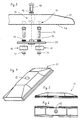
- FIGS. 4 to 6 show a drive plate 10 according to the invention in a perspective view, Side view and top view. As you can see, the drive plate 10 only one single, central attachment opening 12 for attachment to a track on.
- Fig. 1 and 2 illustrate the attachment of the drive plate 10 of the invention to a Track, where there in particular a track according to the invention and several different Chain links are shown.
- the track 14 consists of chain links 101 - 107, the (with Exception of the chain link 101) of left and right link plates 16 and these in Longitudinal and transverse direction interconnecting chain pin 18 exist.
- the chain link 101 is integral with left and right link portions 16a, 16b and one formed therebetween connecting portion 17 is formed.
- the chain link 101 of Fig. 1 and 2 shows a first embodiment of the invention, in the central fastening means by a transversely to a longitudinal center plane 40th extending connecting portion 17 of the chain link 101 is formed.
- a central attachment opening 22 allows a screw connection with a drive plate 10 according to FIG. 3 and 4, as shown in Figs. 1 and 2, right.
- the mounting opening 22 can with Be provided internal thread to the attachment by means of a fastening bolt 42 (as at the links 106 and 107).
- FIG. 1 and 2 show by means of further chain links or link plates pairs 102, 103 a Variant of the fastening solution described above, with no continuous Connection area, but one side of one of the link plates 16 outgoing mounting lug 19 is provided, extending to the vicinity of the opposite link plate extends and in which a slightly eccentric mounting opening 22 is provided.
- the attachment lug 19 even further extends in the direction of the opposite link plate, in which case the attachment opening 22 could be arranged on the longitudinal center plane 40.
- the mounting opening 22 is not on the Longitudinal center plane 40 is located, but laterally offset thereto. Also, the arrangement of several on the longitudinal center plane 40 or laterally slightly offset therefrom mounting holes is possible.
- the chain links 104-107 serve to explain a further embodiment of the invention.
- an adapter plate 24 is first attached.
- fastening bolts 26 engage through fastening bores 28 of the adapter plate 24 and through the mounting holes 20 of the link plates 16 in fastening nuts 30 the inside of the link plates.
- Bolt heads 32 of the fastening bolts 26 are above the adapter plate 24 before.
- the adapter plate 24 has a central attachment opening 34, which for reinforcement in Form of an internally threaded sleeve 36 (Fig. 3) is formed.
- a drive plate 10 according to the invention is provided with a single, central fastening bolt 42, which engages in the internally threaded sleeve 36, bolted to the adapter plate 24, wherein for the positive fixing of the drive plate four cylindrical recesses 44 in which the track 14 facing upper side 46 are provided in the the bolt heads 32 enter, so that the drive plate 10 against rotation about the longitudinal axis of the fastening bolt 42 is secured.
- the fastening bolt 42 of the drive plate 10 engages through a central attachment opening 12, which has a multi-stepped diameter, as shown in FIG. 1 and also FIG. 3 show, namely a central portion 12 a with a diameter of a shaft diameter of the fastening bolt 42 corresponds to a lower portion 12 b with a Diameter corresponding to a bolt head of the mounting bolt 42, and an upper Section 12 c with a diameter corresponding to an outer diameter of the sleeve 36.
- Fig. 3 shows an exploded view in side and sectional view, approximately along the line III-III in Fig. 2, a drive plate mounting 70 according to the invention, with the adapter plate 24 and thus to be screwed drive plate 10.
- the fastening bolts 42 and 26, washers 72 are assigned.
- the fastening nuts 30 are designed as self-locking nuts.
- the drive plate 10 according to the invention is weakened exclusively in its central region by a continuous attachment opening 12, which is, however, unproblematic in view of the expected loads, since bending stresses occur only further outside, namely in the Near the lateral edges of the adapter plate 24. In this area, no debilitating holes are present, so that the stresses arising during operation can be well received.
- the adapter plate 24 in the lateral direction, i. across to Longitudinal direction 40, a little way across the width B of the track 14 and over the outer Edge of the link plates 16 to widen out, as shown in Fig. 2 and 3, so that where the greatest bending moments occur during operation, i. e. at the edge of the adapter plate 24, a certain distance from the inevitable extent debilitating recesses 44 exists.
Landscapes
- Engineering & Computer Science (AREA)
- Chemical & Material Sciences (AREA)
- Combustion & Propulsion (AREA)
- Transportation (AREA)
- Mechanical Engineering (AREA)
- Devices For Conveying Motion By Means Of Endless Flexible Members (AREA)
- Platform Screen Doors And Railroad Systems (AREA)
- Handcart (AREA)
- Machines For Laying And Maintaining Railways (AREA)
- Train Traffic Observation, Control, And Security (AREA)
Applications Claiming Priority (2)
| Application Number | Priority Date | Filing Date | Title |
|---|---|---|---|
| DE102004013705A DE102004013705B4 (de) | 2004-03-18 | 2004-03-18 | Gleiskette für ein Kettenfahrzeug und Laufwerksplatte dafür |
| DE102004013705 | 2004-03-18 |
Publications (3)
| Publication Number | Publication Date |
|---|---|
| EP1577198A2 true EP1577198A2 (fr) | 2005-09-21 |
| EP1577198A3 EP1577198A3 (fr) | 2006-04-26 |
| EP1577198B1 EP1577198B1 (fr) | 2008-01-16 |
Family
ID=34833210
Family Applications (1)
| Application Number | Title | Priority Date | Filing Date |
|---|---|---|---|
| EP05004603A Expired - Lifetime EP1577198B1 (fr) | 2004-03-18 | 2005-03-03 | Section de chenille pour véhicule chenillé avec semelle |
Country Status (3)
| Country | Link |
|---|---|
| EP (1) | EP1577198B1 (fr) |
| AT (1) | ATE383993T1 (fr) |
| DE (2) | DE102004013705B4 (fr) |
Cited By (1)
| Publication number | Priority date | Publication date | Assignee | Title |
|---|---|---|---|---|
| CN113602370A (zh) * | 2021-07-30 | 2021-11-05 | 浙江浙能嘉华发电有限公司 | 一种推煤机转场用单筋履带套 |
Families Citing this family (1)
| Publication number | Priority date | Publication date | Assignee | Title |
|---|---|---|---|---|
| KR102528060B1 (ko) * | 2021-06-16 | 2023-05-04 | 동일고무벨트주식회사 | 스틸트랙용 러버패드 |
Family Cites Families (4)
| Publication number | Priority date | Publication date | Assignee | Title |
|---|---|---|---|---|
| US1485026A (en) * | 1919-03-31 | 1924-02-26 | Gruber Edward | Unit for track belts |
| US1487416A (en) * | 1921-10-01 | 1924-03-18 | Fred B Whitlock | Traction element for tractors |
| GB969732A (en) * | 1962-04-19 | 1964-09-16 | Diehl Karl | Improvements in vehicle track links |
| US4602825A (en) * | 1979-08-23 | 1986-07-29 | Caterpillar Tractor Co. | Anti-torsion means for track assemblies for track-type vehicles |
-
2004
- 2004-03-18 DE DE102004013705A patent/DE102004013705B4/de not_active Expired - Fee Related
-
2005
- 2005-03-03 AT AT05004603T patent/ATE383993T1/de active
- 2005-03-03 EP EP05004603A patent/EP1577198B1/fr not_active Expired - Lifetime
- 2005-03-03 DE DE502005002534T patent/DE502005002534D1/de not_active Expired - Lifetime
Non-Patent Citations (1)
| Title |
|---|
| None |
Cited By (1)
| Publication number | Priority date | Publication date | Assignee | Title |
|---|---|---|---|---|
| CN113602370A (zh) * | 2021-07-30 | 2021-11-05 | 浙江浙能嘉华发电有限公司 | 一种推煤机转场用单筋履带套 |
Also Published As
| Publication number | Publication date |
|---|---|
| DE102004013705B4 (de) | 2007-02-01 |
| EP1577198B1 (fr) | 2008-01-16 |
| DE502005002534D1 (de) | 2008-03-06 |
| DE102004013705A1 (de) | 2005-10-20 |
| ATE383993T1 (de) | 2008-02-15 |
| EP1577198A3 (fr) | 2006-04-26 |
Similar Documents
| Publication | Publication Date | Title |
|---|---|---|
| EP3158851B1 (fr) | Courroie crantée, en particulier pour machines agricoles | |
| DE102006031452A1 (de) | Querbrücke zur Versteifung des Tunnelbereiches einer Bodenstruktur eines Kraftfahrzeuges | |
| DE112012004817T5 (de) | Raupe-Ketten-Verbindungsvorrichtung | |
| EP2778028B1 (fr) | Système de barre pour une chenille d'entraînement d'un véhicule à chenilles | |
| DE2064454C3 (de) | Gleiskette für Gleiskettenfahrzeuge | |
| EP1870324A2 (fr) | Châssis à chaîne | |
| WO2017140652A1 (fr) | Plaque d'usure conçue pour une chenille d'un véhicule chenillé, chenille et engin de chantier | |
| EP1577198B1 (fr) | Section de chenille pour véhicule chenillé avec semelle | |
| DE2811296A1 (de) | Kettenschuhanordnung | |
| EP0367755B1 (fr) | Dispositif d'entraînement | |
| DE2905346A1 (de) | Spurrollenanordnung | |
| DE3016151C2 (de) | Befestigung von Mitnehmern an einer oder mehreren Rundstahlketten | |
| DE20207342U1 (de) | Antriebsrad für ein Laufwerk eines Raupenbandfahrzeugs | |
| DE2232790A1 (de) | Befestigungsanordnung fuer einen zylinder mit kolben | |
| DE102016111542A1 (de) | Schubkette mit standardisiertem Endstück | |
| CH636053A5 (de) | Gleiskette nach dem ein-gelenkbolzen-typ. | |
| WO2019015816A1 (fr) | Roue motrice pour train de roulement à chenilles d'un véhicule à chenilles | |
| DE102009051043A1 (de) | Becherförderer | |
| EP3939867A1 (fr) | Chenilles d'entraînement pour un véhicule à chenilles | |
| DE1234557B (de) | Verbinder-Gleiskette, insbesondere fuer Panzerfahrzeuge | |
| EP4212414B1 (fr) | Chariot inférieur pour machine de travail | |
| EP3031704B1 (fr) | Chenilles | |
| EP1245510A1 (fr) | Courroie crantée comportant des raclettes | |
| WO2020074370A1 (fr) | Ligne de convoyage pour un convoyeur | |
| DE102013211332B4 (de) | Fahrzeugsitz mit Verriegelungseinheit |
Legal Events
| Date | Code | Title | Description |
|---|---|---|---|
| PUAI | Public reference made under article 153(3) epc to a published international application that has entered the european phase |
Free format text: ORIGINAL CODE: 0009012 |
|
| AK | Designated contracting states |
Kind code of ref document: A2 Designated state(s): AT BE BG CH CY CZ DE DK EE ES FI FR GB GR HU IE IS IT LI LT LU MC NL PL PT RO SE SI SK TR |
|
| AX | Request for extension of the european patent |
Extension state: AL BA HR LV MK YU |
|
| PUAL | Search report despatched |
Free format text: ORIGINAL CODE: 0009013 |
|
| AK | Designated contracting states |
Kind code of ref document: A3 Designated state(s): AT BE BG CH CY CZ DE DK EE ES FI FR GB GR HU IE IS IT LI LT LU MC NL PL PT RO SE SI SK TR |
|
| AX | Request for extension of the european patent |
Extension state: AL BA HR LV MK YU |
|
| 17P | Request for examination filed |
Effective date: 20060403 |
|
| AKX | Designation fees paid |
Designated state(s): AT BE BG CH CY CZ DE DK EE ES FI FR GB GR HU IE IS IT LI LT LU MC NL PL PT RO SE SI SK TR |
|
| 17Q | First examination report despatched |
Effective date: 20070416 |
|
| GRAP | Despatch of communication of intention to grant a patent |
Free format text: ORIGINAL CODE: EPIDOSNIGR1 |
|
| GRAS | Grant fee paid |
Free format text: ORIGINAL CODE: EPIDOSNIGR3 |
|
| GRAA | (expected) grant |
Free format text: ORIGINAL CODE: 0009210 |
|
| AK | Designated contracting states |
Kind code of ref document: B1 Designated state(s): AT BE BG CH CY CZ DE DK EE ES FI FR GB GR HU IE IS IT LI LT LU MC NL PL PT RO SE SI SK TR |
|
| REG | Reference to a national code |
Ref country code: GB Ref legal event code: FG4D Free format text: NOT ENGLISH |
|
| REG | Reference to a national code |
Ref country code: CH Ref legal event code: EP |
|
| REG | Reference to a national code |
Ref country code: IE Ref legal event code: FG4D Free format text: LANGUAGE OF EP DOCUMENT: GERMAN |
|
| GBT | Gb: translation of ep patent filed (gb section 77(6)(a)/1977) |
Effective date: 20080206 |
|
| REF | Corresponds to: |
Ref document number: 502005002534 Country of ref document: DE Date of ref document: 20080306 Kind code of ref document: P |
|
| REG | Reference to a national code |
Ref country code: CH Ref legal event code: NV Representative=s name: NOVAGRAAF INTERNATIONAL SA |
|
| PG25 | Lapsed in a contracting state [announced via postgrant information from national office to epo] |
Ref country code: FI Free format text: LAPSE BECAUSE OF FAILURE TO SUBMIT A TRANSLATION OF THE DESCRIPTION OR TO PAY THE FEE WITHIN THE PRESCRIBED TIME-LIMIT Effective date: 20080116 Ref country code: IS Free format text: LAPSE BECAUSE OF FAILURE TO SUBMIT A TRANSLATION OF THE DESCRIPTION OR TO PAY THE FEE WITHIN THE PRESCRIBED TIME-LIMIT Effective date: 20080516 Ref country code: ES Free format text: LAPSE BECAUSE OF FAILURE TO SUBMIT A TRANSLATION OF THE DESCRIPTION OR TO PAY THE FEE WITHIN THE PRESCRIBED TIME-LIMIT Effective date: 20080427 Ref country code: LT Free format text: LAPSE BECAUSE OF FAILURE TO SUBMIT A TRANSLATION OF THE DESCRIPTION OR TO PAY THE FEE WITHIN THE PRESCRIBED TIME-LIMIT Effective date: 20080116 |
|
| ET | Fr: translation filed | ||
| PG25 | Lapsed in a contracting state [announced via postgrant information from national office to epo] |
Ref country code: BG Free format text: LAPSE BECAUSE OF FAILURE TO SUBMIT A TRANSLATION OF THE DESCRIPTION OR TO PAY THE FEE WITHIN THE PRESCRIBED TIME-LIMIT Effective date: 20080416 |
|
| BERE | Be: lapsed |
Owner name: LUTZ, HILDEBRANDT Effective date: 20080331 |
|
| PG25 | Lapsed in a contracting state [announced via postgrant information from national office to epo] |
Ref country code: PL Free format text: LAPSE BECAUSE OF FAILURE TO SUBMIT A TRANSLATION OF THE DESCRIPTION OR TO PAY THE FEE WITHIN THE PRESCRIBED TIME-LIMIT Effective date: 20080116 Ref country code: SI Free format text: LAPSE BECAUSE OF FAILURE TO SUBMIT A TRANSLATION OF THE DESCRIPTION OR TO PAY THE FEE WITHIN THE PRESCRIBED TIME-LIMIT Effective date: 20080116 Ref country code: PT Free format text: LAPSE BECAUSE OF FAILURE TO SUBMIT A TRANSLATION OF THE DESCRIPTION OR TO PAY THE FEE WITHIN THE PRESCRIBED TIME-LIMIT Effective date: 20080616 |
|
| PG25 | Lapsed in a contracting state [announced via postgrant information from national office to epo] |
Ref country code: DK Free format text: LAPSE BECAUSE OF FAILURE TO SUBMIT A TRANSLATION OF THE DESCRIPTION OR TO PAY THE FEE WITHIN THE PRESCRIBED TIME-LIMIT Effective date: 20080116 Ref country code: MC Free format text: LAPSE BECAUSE OF NON-PAYMENT OF DUE FEES Effective date: 20080331 Ref country code: CZ Free format text: LAPSE BECAUSE OF FAILURE TO SUBMIT A TRANSLATION OF THE DESCRIPTION OR TO PAY THE FEE WITHIN THE PRESCRIBED TIME-LIMIT Effective date: 20080116 Ref country code: SE Free format text: LAPSE BECAUSE OF FAILURE TO SUBMIT A TRANSLATION OF THE DESCRIPTION OR TO PAY THE FEE WITHIN THE PRESCRIBED TIME-LIMIT Effective date: 20080416 Ref country code: SK Free format text: LAPSE BECAUSE OF FAILURE TO SUBMIT A TRANSLATION OF THE DESCRIPTION OR TO PAY THE FEE WITHIN THE PRESCRIBED TIME-LIMIT Effective date: 20080116 |
|
| PLBE | No opposition filed within time limit |
Free format text: ORIGINAL CODE: 0009261 |
|
| STAA | Information on the status of an ep patent application or granted ep patent |
Free format text: STATUS: NO OPPOSITION FILED WITHIN TIME LIMIT |
|
| PG25 | Lapsed in a contracting state [announced via postgrant information from national office to epo] |
Ref country code: RO Free format text: LAPSE BECAUSE OF FAILURE TO SUBMIT A TRANSLATION OF THE DESCRIPTION OR TO PAY THE FEE WITHIN THE PRESCRIBED TIME-LIMIT Effective date: 20080116 |
|
| 26N | No opposition filed |
Effective date: 20081017 |
|
| PG25 | Lapsed in a contracting state [announced via postgrant information from national office to epo] |
Ref country code: EE Free format text: LAPSE BECAUSE OF FAILURE TO SUBMIT A TRANSLATION OF THE DESCRIPTION OR TO PAY THE FEE WITHIN THE PRESCRIBED TIME-LIMIT Effective date: 20080116 |
|
| PG25 | Lapsed in a contracting state [announced via postgrant information from national office to epo] |
Ref country code: BE Free format text: LAPSE BECAUSE OF NON-PAYMENT OF DUE FEES Effective date: 20080331 |
|
| PG25 | Lapsed in a contracting state [announced via postgrant information from national office to epo] |
Ref country code: CY Free format text: LAPSE BECAUSE OF FAILURE TO SUBMIT A TRANSLATION OF THE DESCRIPTION OR TO PAY THE FEE WITHIN THE PRESCRIBED TIME-LIMIT Effective date: 20080116 |
|
| PG25 | Lapsed in a contracting state [announced via postgrant information from national office to epo] |
Ref country code: IT Free format text: LAPSE BECAUSE OF FAILURE TO SUBMIT A TRANSLATION OF THE DESCRIPTION OR TO PAY THE FEE WITHIN THE PRESCRIBED TIME-LIMIT Effective date: 20080116 |
|
| PG25 | Lapsed in a contracting state [announced via postgrant information from national office to epo] |
Ref country code: LU Free format text: LAPSE BECAUSE OF NON-PAYMENT OF DUE FEES Effective date: 20080303 Ref country code: HU Free format text: LAPSE BECAUSE OF FAILURE TO SUBMIT A TRANSLATION OF THE DESCRIPTION OR TO PAY THE FEE WITHIN THE PRESCRIBED TIME-LIMIT Effective date: 20080717 |
|
| PG25 | Lapsed in a contracting state [announced via postgrant information from national office to epo] |
Ref country code: TR Free format text: LAPSE BECAUSE OF FAILURE TO SUBMIT A TRANSLATION OF THE DESCRIPTION OR TO PAY THE FEE WITHIN THE PRESCRIBED TIME-LIMIT Effective date: 20080116 |
|
| PG25 | Lapsed in a contracting state [announced via postgrant information from national office to epo] |
Ref country code: GR Free format text: LAPSE BECAUSE OF FAILURE TO SUBMIT A TRANSLATION OF THE DESCRIPTION OR TO PAY THE FEE WITHIN THE PRESCRIBED TIME-LIMIT Effective date: 20080417 |
|
| REG | Reference to a national code |
Ref country code: CH Ref legal event code: PFA Owner name: LUTZ, HILDEBRANDT Free format text: LUTZ, HILDEBRANDT#RINGSTRASSE 78#27612 LOXSTEDT (DE) -TRANSFER TO- LUTZ, HILDEBRANDT#RINGSTRASSE 78#27612 LOXSTEDT (DE) |
|
| REG | Reference to a national code |
Ref country code: FR Ref legal event code: PLFP Year of fee payment: 12 |
|
| REG | Reference to a national code |
Ref country code: FR Ref legal event code: PLFP Year of fee payment: 13 |
|
| REG | Reference to a national code |
Ref country code: FR Ref legal event code: PLFP Year of fee payment: 14 |
|
| PGFP | Annual fee paid to national office [announced via postgrant information from national office to epo] |
Ref country code: NL Payment date: 20240326 Year of fee payment: 20 Ref country code: IE Payment date: 20240319 Year of fee payment: 20 |
|
| PGFP | Annual fee paid to national office [announced via postgrant information from national office to epo] |
Ref country code: AT Payment date: 20240319 Year of fee payment: 20 |
|
| PGFP | Annual fee paid to national office [announced via postgrant information from national office to epo] |
Ref country code: DE Payment date: 20240328 Year of fee payment: 20 Ref country code: GB Payment date: 20240319 Year of fee payment: 20 |
|
| PGFP | Annual fee paid to national office [announced via postgrant information from national office to epo] |
Ref country code: FR Payment date: 20240326 Year of fee payment: 20 |
|
| PGFP | Annual fee paid to national office [announced via postgrant information from national office to epo] |
Ref country code: CH Payment date: 20240401 Year of fee payment: 20 |
|
| REG | Reference to a national code |
Ref country code: DE Ref legal event code: R071 Ref document number: 502005002534 Country of ref document: DE |
|
| REG | Reference to a national code |
Ref country code: NL Ref legal event code: MK Effective date: 20250302 |
|
| REG | Reference to a national code |
Ref country code: CH Ref legal event code: PL |
|
| REG | Reference to a national code |
Ref country code: GB Ref legal event code: PE20 Expiry date: 20250302 |
|
| REG | Reference to a national code |
Ref country code: AT Ref legal event code: MK07 Ref document number: 383993 Country of ref document: AT Kind code of ref document: T Effective date: 20250303 |
|
| PG25 | Lapsed in a contracting state [announced via postgrant information from national office to epo] |
Ref country code: IE Free format text: LAPSE BECAUSE OF EXPIRATION OF PROTECTION Effective date: 20250303 |
|
| REG | Reference to a national code |
Ref country code: IE Ref legal event code: MK9A |
|
| PG25 | Lapsed in a contracting state [announced via postgrant information from national office to epo] |
Ref country code: GB Free format text: LAPSE BECAUSE OF EXPIRATION OF PROTECTION Effective date: 20250302 |