EP1577239B1 - Margeur pour un dispositif de poinçonnage ou estampage - Google Patents
Margeur pour un dispositif de poinçonnage ou estampage Download PDFInfo
- Publication number
- EP1577239B1 EP1577239B1 EP05101440A EP05101440A EP1577239B1 EP 1577239 B1 EP1577239 B1 EP 1577239B1 EP 05101440 A EP05101440 A EP 05101440A EP 05101440 A EP05101440 A EP 05101440A EP 1577239 B1 EP1577239 B1 EP 1577239B1
- Authority
- EP
- European Patent Office
- Prior art keywords
- diecutting
- stamping device
- fact
- sheets
- stack
- Prior art date
- Legal status (The legal status is an assumption and is not a legal conclusion. Google has not performed a legal analysis and makes no representation as to the accuracy of the status listed.)
- Expired - Lifetime
Links
- 238000004080 punching Methods 0.000 title description 59
- 238000004049 embossing Methods 0.000 claims description 50
- 238000000034 method Methods 0.000 abstract description 6
- 230000032258 transport Effects 0.000 description 9
- 238000000151 deposition Methods 0.000 description 4
- 239000002699 waste material Substances 0.000 description 4
- 238000005520 cutting process Methods 0.000 description 2
- 239000000123 paper Substances 0.000 description 2
- 239000000047 product Substances 0.000 description 2
- 241000252254 Catostomidae Species 0.000 description 1
- 230000006978 adaptation Effects 0.000 description 1
- 238000005452 bending Methods 0.000 description 1
- 239000007795 chemical reaction product Substances 0.000 description 1
- 239000003795 chemical substances by application Substances 0.000 description 1
- 230000007423 decrease Effects 0.000 description 1
- 238000004519 manufacturing process Methods 0.000 description 1
- 239000005022 packaging material Substances 0.000 description 1
- 238000004806 packaging method and process Methods 0.000 description 1
- 238000000926 separation method Methods 0.000 description 1
- 238000010008 shearing Methods 0.000 description 1
- 239000007858 starting material Substances 0.000 description 1
- 238000009966 trimming Methods 0.000 description 1
Images


Classifications
-
- B—PERFORMING OPERATIONS; TRANSPORTING
- B65—CONVEYING; PACKING; STORING; HANDLING THIN OR FILAMENTARY MATERIAL
- B65H—HANDLING THIN OR FILAMENTARY MATERIAL, e.g. SHEETS, WEBS, CABLES
- B65H3/00—Separating articles from piles
- B65H3/08—Separating articles from piles using pneumatic force
- B65H3/0808—Suction grippers
- B65H3/0816—Suction grippers separating from the top of pile
-
- B—PERFORMING OPERATIONS; TRANSPORTING
- B65—CONVEYING; PACKING; STORING; HANDLING THIN OR FILAMENTARY MATERIAL
- B65H—HANDLING THIN OR FILAMENTARY MATERIAL, e.g. SHEETS, WEBS, CABLES
- B65H11/00—Feed tables
- B65H11/002—Feed tables incorporating transport belts
-
- B—PERFORMING OPERATIONS; TRANSPORTING
- B65—CONVEYING; PACKING; STORING; HANDLING THIN OR FILAMENTARY MATERIAL
- B65H—HANDLING THIN OR FILAMENTARY MATERIAL, e.g. SHEETS, WEBS, CABLES
- B65H3/00—Separating articles from piles
- B65H3/44—Simultaneously, alternately, or selectively separating articles from two or more piles
-
- B—PERFORMING OPERATIONS; TRANSPORTING
- B65—CONVEYING; PACKING; STORING; HANDLING THIN OR FILAMENTARY MATERIAL
- B65H—HANDLING THIN OR FILAMENTARY MATERIAL, e.g. SHEETS, WEBS, CABLES
- B65H35/00—Delivering articles from cutting or line-perforating machines; Article or web delivery apparatus incorporating cutting or line-perforating devices, e.g. adhesive tape dispensers
- B65H35/0006—Article or web delivery apparatus incorporating cutting or line-perforating devices
-
- B—PERFORMING OPERATIONS; TRANSPORTING
- B65—CONVEYING; PACKING; STORING; HANDLING THIN OR FILAMENTARY MATERIAL
- B65H—HANDLING THIN OR FILAMENTARY MATERIAL, e.g. SHEETS, WEBS, CABLES
- B65H2601/00—Problem to be solved or advantage achieved
- B65H2601/40—Increasing or maximizing
- B65H2601/42—Increasing or maximizing entities relating to the handling machine
- B65H2601/421—Capacity
-
- B—PERFORMING OPERATIONS; TRANSPORTING
- B65—CONVEYING; PACKING; STORING; HANDLING THIN OR FILAMENTARY MATERIAL
- B65H—HANDLING THIN OR FILAMENTARY MATERIAL, e.g. SHEETS, WEBS, CABLES
- B65H2601/00—Problem to be solved or advantage achieved
- B65H2601/40—Increasing or maximizing
- B65H2601/42—Increasing or maximizing entities relating to the handling machine
- B65H2601/422—Versatility
Definitions
- the invention relates to an investor for a punching or embossing device, as well as a punching or embossing device with such an investor, and a method for punching or embossing of sheets with a stamping or embossing device.
- punching As punching the cutting is referred to as closed, geometric blank forms that can be circular, oval or polygonal as well as fantasy shapes of all kinds. Even the practices practiced in print finishing such as punching with punch, repel corners and register punching are counted to this area.
- the punching is carried out against a punching pad or against stamp partly it is also shearing operations (cf print finishing, training manual for bookbinders, Bundesvious Druck e.V. 1996, page 351 ff.).
- Packaging material made of paper, cardboard, cardboard or corrugated cardboard are mainly punched in sheet format. When punching but also creasing lines or blind embossing can be introduced into the benefit. This complex process makes it indispensable to punch the sheets individually, as the end products are usually sophisticated packaging. For optimum results, stamping tools with the lowest tolerances and extremely precise and reliable punching machines are required.
- stamping machines are often so-called flat bed punches in which the printed sheets stacked on a pallet are fed to the punching machine.
- the sheets are precisely aligned at three points with side and front marks, taken over by a gripper carriage with a gripper bar and positioned exactly between the die and the punching plate.
- the complete sheet is punched in a stroke in the next station (breaking station), the waste is mechanically removed by stripping tools.
- Such a flat bed punch is for example from the DE 30 44 083 A1 known.
- the two tables are equipped with cutting and scoring tools or corresponding counter tools with which punched out of the cyclically guided between the table surface sheets the benefits and at the same time pressed the necessary for clean folding grooves. In the subsequent breakout the waste is removed by machine tools. Depending on the equipment of the machine finally the punched benefits can be separated in a designatedWhentrenn arthritis.
- punching and embossing machines process large format products, for example in a format up to 105 x 74 or 100 x 140. To a lesser extent, even small sheet sizes (for example in the format 50 x 70) are processed. Smaller punching or embossing machines are sometimes developed and used for these smaller sheet sizes, or alternatively, when investing in a small format machine that processes small formats on large machines. The latter may be more economical than the purchase of a small format machine, but the economy is still relatively low when a large-format machine is used only for punching or embossing small-sized sheet.
- the US 3,391,924 A1 describes a device in which two separate sheets are fed from two adjacent sheet stacks of a printing press.
- the sheet feeder has suction means to lift and sing single sheets from a respective stack of sheets. Two sheets are simultaneously deducted from the two sheet stacks.
- the disadvantage of this is that when a sheet stack has to be refilled, the machine must be stopped. This has a negative effect on the production performance of a stamping or embossing device. It is therefore the object of the present invention to make the stamping or embossing of small-sized sheets with a large-sized punching or embossing device more economical, and to increase the performance of a large-sized punching or embossing device for small sheet sizes.
- the feeder according to the invention is thus distinguished by the fact that several stacks are provided next to one another in the transport direction, of which the feeder withdraws sheets by means of suitable means and supplies them to a punching or embossing device.
- the term investor is quite generally for those device that feeds the punching or embossing device sheet.
- This inventive investor could also consist of two or more conventional, smaller sized Einzelbogenanlegern parallel to each other operate.
- these plurality of single-sheet investors only form a feeder according to the invention, so that such embodiments are likewise encompassed by the invention.
- the feeder can thereby simultaneously withdraw sheets from several stacks and feed them to the punching and embossing apparatus, although sequential peeling of the sheets from different stacks may also be advantageous, particularly with regard to refilling the stacks from which the feeder withdraws the sheets .
- a doubling of the throughput of the punching or embossing device so that high speeds per sheet can be achieved in this way, for example 14 000 sheets per hour.
- the performance of the punching device increases accordingly. In this way, therefore, the sheet throughput can be increased by the punching or embossing device at the same number of strokes of the punching or embossing device by a multiple.
- the means for applying at least one separating sucker per stack is operable independently of the separating suckers of the other stack.
- the punching or embossing device is in the punching or embossing device is a large-sized punching or embossing device and the sheet to small format sheet, in particular a punching and embossing device for a 105 x 74 format and the Sheet by sheet of 50 x 70 format.
- the means for applying sheets are designed such that even sheets from a single stack can be applied.
- the punching or embossing device with the same feeder can also process those products which were originally intended for processing with the punching or embossing device of the corresponding format.
- the means for applying at least one independent suction head per stack, for sucking the uppermost sheet of the stack is further developed.
- the means for applying at least one stack each have a control roller and / or a sheet flap.
- the means for applying at least each stack on a side mark, for lateral alignment of the respective sheet also have an independent drive.
- the page marks can be operated in such a way that the respective sheets of all the stacks are aligned laterally at the same time.
- the means for applying at least one stack each have a front mark for aligning the front side of the sheet.
- the front marks for aligning the front of the sheet per stack to an independent drive.
- the front marks can be operated in such a way that the respective sheets of all the stacks are aligned simultaneously.
- the invention also relates to a punching or embossing device having a feeder according to the invention with one, several or all previous features.
- the punching or embossing device gripper on a gripper bar, for transporting the sheet through the punching or embossing device, said gripper and gripper bar are designed such that the grippers are variably attached to the gripper bar.
- the rapier can be adapted by means of variably attachable gripper on the plurality of sheets that are applied by juxtaposed stacks. It can also be advantageously achieved in this way that the grippers can assume an ideal positioning with respect to the edges of the sheet. This can prevent the corners of the sheets from bending when punched.
- each stack in the feeder are assigned a set of Feinjustagestoffn.
- FIG. 1 shows a schematic representation of a known punching or embossing device 1.
- FIG. 1 shows a schematic representation of a known punching or embossing device 1.
- drive and guide means cams and control means to illustrate the effects of the device is not shown or only described in general terms.
- FIG. 1 the basic structure of a sheet punching and embossing machine 1 for punching, breaking and depositing sheets of paper, cardboard and the like is shown.
- the punching and embossing machine 1 consists of a punching device 2, a breakout device 3 and a depositing device 4, which are supported and enclosed by a common machine housing 5.
- the sheet 6 are gripped by mounted on revolving chains 7 rapiers 8 at its front edge and intermittently pulled through the various stations 2, 3 and 4 of the punching and embossing machine 1.
- the punching station 2 includes a device consisting of a lower table 9 and an upper table 10.
- the lower table 9 is fixedly mounted in the machine frame and provided with a counter plate to the punching knife.
- the upper table 10 is mounted vertically movable and driven by a drive for the device.
- the gripper bar 8 transports the sheet 6 from the punching and embossing station 2 in the subsequent breaking station 3, which may be equipped with breakout tools.
- the breaking station 3 are pushed out of the sheet with the help of the break-off tools the unnecessary pieces of waste from the sheet, whereby these waste pieces 11 fall into a container-like carriage 12 inserted below the station.
- the depositing station 4 can also contain a pallet 13, on which the individual sheets are stacked in the form of a stack 14, so that after reaching a certain stack height, the pallets with the stacked sheets 14 can be moved away from the area of the punching and embossing machine 1.
- the chains 7 carry a plurality of gripper bars 8, for example, there are eight, so that multiple sheets 6 can be processed simultaneously in the various stations 2, 3 and 4.
- FIG. 1 and in FIG. 2 is the transport movement of the sheet 6, 6a, 6b represented by the punching and embossing device 1 by the arrow with the reference TB.
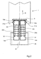
- a first stack 16a and next to a second stack 16b are shown in the feeder 30.
- the two stacks 16a, 16b are shown symmetrically to the center line M of feeder 30 and punching or embossing device 1.
- feeder 30 a device which supplies the punching or embossing device 1 sheet 6, 6a, 6b.
- This inventive feeder could also consist of two or more conventional, smaller sized Einzelbogenanlegern operated in parallel.
- Suction heads 42a, 42b are arranged at the upper end of the stack 16a, 16b. These suction heads 42a, 42b are connected to a suction device 40, 40a, 40b. It may be in one embodiment, as in FIG. 3 shown to act as a common suction device 40 or, as in the embodiment in FIG. 4 shown to each have a suction device 40a, 40b, which is associated with the corresponding stack. In the embodiment in FIG. 3 For example, the suction heads 42a, 42b may be connected to the suction device 40 such that the suction heads 42a, 42b are supplied with suction air independently of each other.
- the suction device 40, 40a, 40b generates at the suction heads 42a, 42b a suitable cycled negative pressure, so that the suction heads 42a, 42b can grip the uppermost sheets 6a, 6b of the stacks 16a, 16b and feed them to a transport device 20a, 20b.
- each stack 16a, 16b are each associated with 2 suction heads 42a, 42b.
- clock rollers 32 are arranged above the stacks 16a, 16b. These clock rollers 32 generate a scale flow of the sheets 6, 6a, 6b in the direction of the transport movement TB to the punching or embossing device 1.
- the scale flow of the sheets 6, 6a, 6b is moved forward by pairs of conveyor belts 20.
- the pairs of conveyor belts are advantageously driven separately in batches.
- the conveyor belts 20, which are assigned to the respective stacks 16a, 16b synchronize with each other by mechanical or electronic means.
- side marks 21a, 21b and not shown known to those skilled in front brands for lateral alignment and orientation of the front of the sheet 6a, 6b.
- the side marks 21a, 21b and front marks, respectively are associated with the respective stacks 16a, 16b so as to independently align the respective sheets 6a, 6b.
- the alignment takes place simultaneously for all the sheets which are to be punched together in the following.
- the sheets 6a, 6b After the sheets 6a, 6b have been aligned, they are gripped by grippers 18a, 18b attached to a rapier bar 8.
- the grippers 18a, 18b are slidably mounted on the gripper bar 8, so that the position of the grippers 18a, 18b relative to the sheets 6a, 6b can be adjusted, so that a suitable adaptation to the format and number of simultaneously processed sheet 6a, 6b is possible.
- the punching or embossing device 1 comprises a stacking device, not shown, which generates the required number of stacks 16a, 16b on a pallet, which can then find application in the feeder 30.
Landscapes
- Engineering & Computer Science (AREA)
- Mechanical Engineering (AREA)
- Sheets, Magazines, And Separation Thereof (AREA)
- Machines For Manufacturing Corrugated Board In Mechanical Paper-Making Processes (AREA)
- Perforating, Stamping-Out Or Severing By Means Other Than Cutting (AREA)
- Delivering By Means Of Belts And Rollers (AREA)
- Registering Or Overturning Sheets (AREA)
- Feeding Of Articles By Means Other Than Belts Or Rollers (AREA)
Claims (14)
- Dispositif de perforation ou de découpe (1) de grand format destiné au traitement de feuilles (6, 6a, 6b) de petit format, le dispositif de perforation ou de découpe (1) comportant un margeur (30) avec des moyens (20a, 20b, 21a, 21b, 30, 32, 40, 40a, 40b, 42a, 42b) destinés à saisir des feuilles (6, 6a, 6b) dans une pluralité de piles (16a, 16b), les piles (16a, 16b) étant disposées parallèlement entre elles, les unes à côté des autres et parallèlement à la direction de transport (TB), caractérisé en ce que les moyens (20a, 20b, 21a, 21b, 30, 32, 40, 40a, 40b, 42a, 42b) destinés à saisir comportent au moins un dispositif d'aspiration (40, 40a, 40b) par pile (16a, 16b) et en ce que ledit au moins un dispositif d'aspiration (40, 40b) d'une pile (16a) peut être utilisé indépendamment dudit au moins un dispositif d'aspiration (40, 40b) de l'autre pile (16b).
- Dispositif de perforation ou de découpe (1) selon la revendication 1, caractérisé en ce que les moyens (20a, 20b, 21a, 21b, 30, 32, 40, 40a, 40b, 42a, 42b) destinés à saisir sont configurés de telle sorte qu'ils peuvent également saisir des feuilles (6, 6a, 6b) d'une seule pile (16a, 16b).
- Dispositif de perforation ou de découpe (1) selon l'une quelconque des revendications 1 à 2, caractérisé en ce que les moyens (20a, 20b, 21a, 21b, 30, 32, 40, 40a, 40b, 42a, 42b) destinés à saisir comportent pour chaque pile (16a, 16b) au moins une tête d'aspiration (42a, 42b) indépendante, destinée à aspirer la feuille (6a, 6b) supérieure de la pile (16a, 16b).
- Dispositif de perforation ou de découpe (1) selon l'une quelconque des revendications 1 à 3, caractérisé en ce que les moyens (20a, 20b, 21a, 21b, 30, 32, 40, 40a, 40b, 42a, 42b) destinés à saisir comportent pour chaque pile (16a, 16b) au moins un élément de transport (20a, 20b), en particulier au moins une bande transporteuse (20a, 20b).
- Dispositif de perforation ou de découpe (1) selon la revendication 4, caractérisé en ce que l'élément de transport (20a, 20b) de chaque pile (16a, 16b) comporte un système d'entraînement indépendant.
- Dispositif selon l'une quelconque des revendications 1 à 5, caractérisé en ce que les moyens (20a, 20b, 21a, 21b, 30, 32, 40, 40a, 40b, 42a, 42b) destinés à saisir comportent au moins un rouleau d'alimentation intermittente (32) par pile (16a, 16b).
- Dispositif de perforation ou de découpe (1) selon l'une quelconque des revendications 1 à 6, caractérisé en ce que les moyens (20a, 20b, 21a, 21b, 30, 32, 40, 40a, 40b, 42a, 42b) destinés à saisir comportent au moins un abattant de feuilles par pile (16a, 16b).
- Dispositif de perforation ou de découpe (1) selon l'une quelconque des revendications 1 à 7, caractérisé en ce que les moyens (20a, 20b, 21a, 21b, 30, 32, 40, 40a, 40b, 42a, 42b) destinés à saisir comportent pour chaque pile (16a, 16b) au moins un repère latéral (21a, 21b) pour l'alignement latéral de chaque feuille (6, 6a, 6b).
- Dispositif de perforation ou de découpe (1) selon la revendication 8, caractérisé en ce que les repères latéraux (21a, 21b) destinés à l'alignement latéral comportent un système d'entraînement indépendant pour chaque pile (16a, 16b).
- Dispositif de perforation ou de découpe (1) selon l'une quelconque des revendications 8 à 9, caractérisé en ce que les repères latéraux (21a, 21b) de toutes les piles (16a, 16b) alignent simultanément les feuilles (6, 6a, 6b) respectives.
- Dispositif de perforation ou de découpe (1) selon l'une quelconque des revendications 8 à 10, caractérisé en ce que les moyens (20a, 20b, 21a, 21b, 30, 32, 40, 40a, 40b, 42a, 42b) destinés à saisir comportent pour chaque pile (16a, 16b) au moins un repère frontal destiné à aligner le côté frontal des feuilles (6, 6a, 6b).
- Dispositif de perforation ou de découpe (1) selon la revendication 1, caractérisé en ce que le dispositif de perforation ou de découpe (1) comporte des organes de préhension (18a, 18b) sur une tige de préhension (8), destinés à transporter les feuilles (6, 6a, 6b) à travers le dispositif de perforation ou de découpe (1), les organes de préhension (18a, 18b) et la tige de préhension (8) étant configurés de telle sorte que les organes de préhension (18a, 18b) peuvent être montés de manière variable sur la tige de préhension (8).
- Dispositif de perforation ou de découpe (1) selon la revendication 12, caractérisé en ce que le dispositif de perforation ou de découpe (1) comporte des moyens d'ajustage précis, un jeu de moyens d'ajustage précis étant associé à chaque pile (16a, 16b).
- Dispositif de perforation ou de découpe (1) selon l'une quelconque des revendications 12 à 13, caractérisé en ce que le dispositif de perforation ou de découpe (1) comporte un dispositif d'empilage préliminaire, qui est configuré de telle sorte qu'il est apte à constituer plusieurs piles (16a, 16b) alignées sur une palette.
Applications Claiming Priority (2)
| Application Number | Priority Date | Filing Date | Title |
|---|---|---|---|
| DE102004012694 | 2004-03-16 | ||
| DE102004012694A DE102004012694A1 (de) | 2004-03-16 | 2004-03-16 | Anleger für eine Stanz- oder Prägevorrichtung |
Publications (3)
| Publication Number | Publication Date |
|---|---|
| EP1577239A2 EP1577239A2 (fr) | 2005-09-21 |
| EP1577239A3 EP1577239A3 (fr) | 2006-05-31 |
| EP1577239B1 true EP1577239B1 (fr) | 2008-07-23 |
Family
ID=34833128
Family Applications (1)
| Application Number | Title | Priority Date | Filing Date |
|---|---|---|---|
| EP05101440A Expired - Lifetime EP1577239B1 (fr) | 2004-03-16 | 2005-02-25 | Margeur pour un dispositif de poinçonnage ou estampage |
Country Status (6)
| Country | Link |
|---|---|
| US (1) | US7516952B2 (fr) |
| EP (1) | EP1577239B1 (fr) |
| JP (1) | JP2005263494A (fr) |
| CN (1) | CN100513278C (fr) |
| AT (1) | ATE402109T1 (fr) |
| DE (2) | DE102004012694A1 (fr) |
Families Citing this family (12)
| Publication number | Priority date | Publication date | Assignee | Title |
|---|---|---|---|---|
| DE102006049111A1 (de) * | 2006-10-18 | 2008-04-30 | Heidelberger Druckmaschinen Ag | Flachbett-Bogenstanzmaschine |
| DE102006053577A1 (de) * | 2006-11-14 | 2008-05-15 | Heidelberger Druckmaschinen Ag | Flachbett-Bogenstanzmaschine |
| DE102007053806A1 (de) * | 2007-11-12 | 2009-05-14 | Heidelberger Druckmaschinen Ag | Rotationsprägeeinrichtung |
| DE102008005214A1 (de) | 2008-01-18 | 2009-07-23 | Gallus Stanz- Und Druckmaschinen Gmbh | Flachbettstanzmodul zum Stanzen eines Bedruckstoffes und Flachbettstanze |
| IT1394149B1 (it) | 2008-09-12 | 2012-05-25 | Panotec Srl | Apparecchiatura per il caricamento di un materiale relativamente rigido, ad esempio cartone, e relativo procedimento di caricamento |
| DE102008058806A1 (de) * | 2008-11-24 | 2010-05-27 | Joachim Jakob | Vorrichtung zum Bearbeiten eines Werkstoffstreifens |
| US8066198B2 (en) * | 2009-01-16 | 2011-11-29 | Dana Canada Corporation | Valve apparatus for regulating a heat exchange liquid |
| DE102012025443A1 (de) | 2012-12-21 | 2014-06-26 | Gallus Stanz- Und Druckmaschinen Gmbh | Fertigungssystem mit Flachbett- und Rotationsstanze |
| IL240822B (en) | 2014-09-23 | 2020-03-31 | Heidelberger Druckmasch Ag | Sheet feeding device |
| CN104495432B (zh) * | 2014-12-16 | 2018-01-09 | 陈小东 | 自动压痕系统和自动压痕方法 |
| JP6932380B2 (ja) * | 2018-09-05 | 2021-09-08 | 株式会社ウエーブ | 箔押し機用給排紙方法および装置 |
| ES3036086T3 (en) * | 2019-12-18 | 2025-09-12 | Heidelberger Druckmasch Ag | Method for operating a flat bed press for cutting out |
Family Cites Families (19)
| Publication number | Priority date | Publication date | Assignee | Title |
|---|---|---|---|---|
| US2060800A (en) * | 1935-12-06 | 1936-11-17 | Ehrig Hans | Sheet feeder |
| US2146945A (en) * | 1936-07-31 | 1939-02-14 | Ehrig Hans | Sheet feeder |
| US3391924A (en) * | 1966-07-29 | 1968-07-09 | Addressograph Multigraph | Sheet feeding mechanism |
| DE1816425A1 (de) * | 1968-12-21 | 1970-06-25 | Mabeg Maschb Gmbh Nachf Hense | Einrichtung an einer pneumatischen Bogentrennvorrichtung |
| US3756586A (en) * | 1971-12-16 | 1973-09-04 | Ibm | Selective cut sheet feed device |
| DE2802596A1 (de) * | 1978-01-21 | 1979-07-26 | Schuler Gmbh L | Vorrichtung zum entstapeln und abfoerdern tafelfoermiger werkstuecke |
| DE3044083C2 (de) * | 1980-11-24 | 1990-05-10 | Bobst S.A., Lausanne | Stanzeinrichtungen für Stanzautomaten zum Stanzen von Bögen aus Papier, Pappe u. dgl. |
| DE3701603A1 (de) * | 1987-01-21 | 1988-08-04 | Jagenberg Ag | Flachbett-bogenstanzmaschine, insbesondere zur herstellung von papier- oder kartonzuschnitten |
| CH681873A5 (fr) * | 1990-04-09 | 1993-06-15 | Bobst Sa | |
| DE4129029A1 (de) * | 1991-08-31 | 1993-03-04 | Blohm Voss Ag | Flachbett-stanzmaschine zum stanzen von flachen gegenstaenden, insbesondere boegen aus papier, pappe oder dergleichen |
| DE4218788A1 (de) * | 1992-06-06 | 1993-12-09 | Bartling Werke Friedr Aug Bart | Vorrichtung zur Fertigung von Schalen o. dgl. aus einer Kartonbahn |
| US5570172A (en) * | 1995-01-18 | 1996-10-29 | Xerox Corporation | Two up high speed printing system |
| DE19516073B4 (de) * | 1995-05-04 | 2012-03-22 | Heidelberger Druckmaschinen Ag | Vorrichtung zum Stanzen von Nutzen aus Bögen |
| DE19516022A1 (de) * | 1995-05-04 | 1996-11-07 | Wupa Maschinen & Service Gmbh | Vorrichtung zum Greifen von Bögen |
| DE19755519C2 (de) * | 1997-12-13 | 2003-11-27 | Koenig & Bauer Ag | Vorrichtung zum Zuführen von Bogen |
| GB2340109A (en) * | 1998-07-28 | 2000-02-16 | Heidelberger Druckmasch Ag | Feeding signatures from stacks to a compiling conveyor |
| EP1074496B1 (fr) * | 1999-07-26 | 2007-03-28 | Grapha Holding AG | Dispositif pour assembler des imprimés |
| DE10141964B4 (de) * | 2001-08-23 | 2006-02-23 | Bielomatik Leuze Gmbh + Co.Kg | Verfahren und Vorrichtung zum Stapeln von Riesen |
| DE10216134A1 (de) * | 2002-04-12 | 2003-10-23 | Koenig & Bauer Ag | Verfahren zum wahlweisen Zuführen von Bogen oder Vorlaufbogen |
-
2004
- 2004-03-16 DE DE102004012694A patent/DE102004012694A1/de not_active Withdrawn
-
2005
- 2005-02-25 EP EP05101440A patent/EP1577239B1/fr not_active Expired - Lifetime
- 2005-02-25 DE DE502005004767T patent/DE502005004767D1/de not_active Expired - Lifetime
- 2005-02-25 AT AT05101440T patent/ATE402109T1/de not_active IP Right Cessation
- 2005-03-15 JP JP2005072656A patent/JP2005263494A/ja not_active Withdrawn
- 2005-03-16 CN CNB2005100558235A patent/CN100513278C/zh not_active Expired - Fee Related
- 2005-03-16 US US11/081,482 patent/US7516952B2/en not_active Expired - Fee Related
Also Published As
| Publication number | Publication date |
|---|---|
| US20050206066A1 (en) | 2005-09-22 |
| DE502005004767D1 (de) | 2008-09-04 |
| JP2005263494A (ja) | 2005-09-29 |
| CN1669895A (zh) | 2005-09-21 |
| DE102004012694A1 (de) | 2005-10-06 |
| EP1577239A2 (fr) | 2005-09-21 |
| US7516952B2 (en) | 2009-04-14 |
| ATE402109T1 (de) | 2008-08-15 |
| EP1577239A3 (fr) | 2006-05-31 |
| CN100513278C (zh) | 2009-07-15 |
Similar Documents
| Publication | Publication Date | Title |
|---|---|---|
| DE102004058598B4 (de) | Vorrichtung zur veredelnden Bearbeitung von bogenförmigen Substraten | |
| EP1914049B1 (fr) | Presse à platines | |
| EP1882657B1 (fr) | Système de freinage pour feuilles | |
| EP2452790B1 (fr) | Station de traitement pour une estampilleuse et procédé de sortie de feuilles d'ébauche | |
| DE10356413A1 (de) | Vorrichtung zur veredelnden Bearbeitung von bogenförmigen Substraten | |
| DE102007014315A1 (de) | Verfahren zum Stanzen und Bogenstanz- und -prägemaschine | |
| DE102013010750A1 (de) | Bogenanleger und Verfahren zur Schuppenstrombildung | |
| EP1577239B1 (fr) | Margeur pour un dispositif de poinçonnage ou estampage | |
| DE102008048287A1 (de) | Vorrichtung und Verfahren zum Falzen von Bogen | |
| EP2087972B1 (fr) | Dispositif d'estampillage | |
| WO2021233592A1 (fr) | Machine de traitement de feuilles dotée d'au moins un système de transport de transfert et procédé de transport de feuilles dans une machine de traitement de feuilles | |
| DE102010024274A1 (de) | Stanz- und/oder Prägestation einer Bogenstanzmaschine | |
| DE102012019051B4 (de) | Transportvorrichtung für Bogen mit obenliegender Blasluftkammer | |
| EP2165954B1 (fr) | Machine de traitement de feuilles et procédé de dépôt de feuilles | |
| DE19543382C2 (de) | Verfahren zum Vereinzeln von Bogen und Anleger für eine Bogendruckmaschine zur Durchführung des Verfahrens | |
| DE102008011051A1 (de) | Bogenstanz- und -prägemaschine | |
| DE102011118905B4 (de) | Bearbeitungsstation für eine Stanzmaschine | |
| EP3994088B1 (fr) | Machine à poinçonner dotée d'un système de transport sous forme d'un système de pinces à chaîne, et procédé d'ouverture d'au moins un élément de retenue | |
| EP1219556B1 (fr) | Méthode et dispositif pour la production d'un produit imprimé avec unité d' imprimerie, unité de coupage et dispositif à empiler | |
| DE102013008298A1 (de) | Transporteinrichtung für Bogen | |
| EP1882565A2 (fr) | Procédé de döcoupe et presse de découpage et de rainurage | |
| DE102007043106A1 (de) | Druck- und Stanzmaschine | |
| DE102006049112A1 (de) | Flachbrett-Bogenstanzmaschine | |
| DE102014013669A1 (de) | Stanzmaschine mit Greiferrandausstreifer | |
| DE102005058521A1 (de) | Bogendruckmaschine |
Legal Events
| Date | Code | Title | Description |
|---|---|---|---|
| PUAI | Public reference made under article 153(3) epc to a published international application that has entered the european phase |
Free format text: ORIGINAL CODE: 0009012 |
|
| AK | Designated contracting states |
Kind code of ref document: A2 Designated state(s): AT BE BG CH CY CZ DE DK EE ES FI FR GB GR HU IE IS IT LI LT LU MC NL PL PT RO SE SI SK TR |
|
| AX | Request for extension of the european patent |
Extension state: AL BA HR LV MK YU |
|
| RIN1 | Information on inventor provided before grant (corrected) |
Inventor name: BITTNER, WOLFGANG Inventor name: PUETZ, ANDRE Inventor name: KLAASSEN, GERHARD Inventor name: KOEPKE, PETER |
|
| PUAL | Search report despatched |
Free format text: ORIGINAL CODE: 0009013 |
|
| AK | Designated contracting states |
Kind code of ref document: A3 Designated state(s): AT BE BG CH CY CZ DE DK EE ES FI FR GB GR HU IE IS IT LI LT LU MC NL PL PT RO SE SI SK TR |
|
| AX | Request for extension of the european patent |
Extension state: AL BA HR LV MK YU |
|
| 17P | Request for examination filed |
Effective date: 20061130 |
|
| AKX | Designation fees paid |
Designated state(s): AT BE BG CH CY CZ DE DK EE ES FI FR GB GR HU IE IS IT LI LT LU MC NL PL PT RO SE SI SK TR |
|
| 17Q | First examination report despatched |
Effective date: 20070117 |
|
| GRAP | Despatch of communication of intention to grant a patent |
Free format text: ORIGINAL CODE: EPIDOSNIGR1 |
|
| GRAS | Grant fee paid |
Free format text: ORIGINAL CODE: EPIDOSNIGR3 |
|
| GRAA | (expected) grant |
Free format text: ORIGINAL CODE: 0009210 |
|
| AK | Designated contracting states |
Kind code of ref document: B1 Designated state(s): AT BE BG CH CY CZ DE DK EE ES FI FR GB GR HU IE IS IT LI LT LU MC NL PL PT RO SE SI SK TR |
|
| REG | Reference to a national code |
Ref country code: GB Ref legal event code: FG4D Free format text: NOT ENGLISH |
|
| REG | Reference to a national code |
Ref country code: CH Ref legal event code: EP |
|
| REG | Reference to a national code |
Ref country code: IE Ref legal event code: FG4D Free format text: LANGUAGE OF EP DOCUMENT: GERMAN |
|
| REF | Corresponds to: |
Ref document number: 502005004767 Country of ref document: DE Date of ref document: 20080904 Kind code of ref document: P |
|
| NLV1 | Nl: lapsed or annulled due to failure to fulfill the requirements of art. 29p and 29m of the patents act | ||
| PG25 | Lapsed in a contracting state [announced via postgrant information from national office to epo] |
Ref country code: LT Free format text: LAPSE BECAUSE OF FAILURE TO SUBMIT A TRANSLATION OF THE DESCRIPTION OR TO PAY THE FEE WITHIN THE PRESCRIBED TIME-LIMIT Effective date: 20080723 Ref country code: NL Free format text: LAPSE BECAUSE OF FAILURE TO SUBMIT A TRANSLATION OF THE DESCRIPTION OR TO PAY THE FEE WITHIN THE PRESCRIBED TIME-LIMIT Effective date: 20080723 Ref country code: IS Free format text: LAPSE BECAUSE OF FAILURE TO SUBMIT A TRANSLATION OF THE DESCRIPTION OR TO PAY THE FEE WITHIN THE PRESCRIBED TIME-LIMIT Effective date: 20081123 |
|
| PG25 | Lapsed in a contracting state [announced via postgrant information from national office to epo] |
Ref country code: ES Free format text: LAPSE BECAUSE OF FAILURE TO SUBMIT A TRANSLATION OF THE DESCRIPTION OR TO PAY THE FEE WITHIN THE PRESCRIBED TIME-LIMIT Effective date: 20081103 Ref country code: BG Free format text: LAPSE BECAUSE OF FAILURE TO SUBMIT A TRANSLATION OF THE DESCRIPTION OR TO PAY THE FEE WITHIN THE PRESCRIBED TIME-LIMIT Effective date: 20081023 Ref country code: PT Free format text: LAPSE BECAUSE OF FAILURE TO SUBMIT A TRANSLATION OF THE DESCRIPTION OR TO PAY THE FEE WITHIN THE PRESCRIBED TIME-LIMIT Effective date: 20081223 Ref country code: SI Free format text: LAPSE BECAUSE OF FAILURE TO SUBMIT A TRANSLATION OF THE DESCRIPTION OR TO PAY THE FEE WITHIN THE PRESCRIBED TIME-LIMIT Effective date: 20080723 Ref country code: FI Free format text: LAPSE BECAUSE OF FAILURE TO SUBMIT A TRANSLATION OF THE DESCRIPTION OR TO PAY THE FEE WITHIN THE PRESCRIBED TIME-LIMIT Effective date: 20080723 |
|
| REG | Reference to a national code |
Ref country code: IE Ref legal event code: FD4D |
|
| PG25 | Lapsed in a contracting state [announced via postgrant information from national office to epo] |
Ref country code: EE Free format text: LAPSE BECAUSE OF FAILURE TO SUBMIT A TRANSLATION OF THE DESCRIPTION OR TO PAY THE FEE WITHIN THE PRESCRIBED TIME-LIMIT Effective date: 20080723 Ref country code: IE Free format text: LAPSE BECAUSE OF FAILURE TO SUBMIT A TRANSLATION OF THE DESCRIPTION OR TO PAY THE FEE WITHIN THE PRESCRIBED TIME-LIMIT Effective date: 20080723 Ref country code: DK Free format text: LAPSE BECAUSE OF FAILURE TO SUBMIT A TRANSLATION OF THE DESCRIPTION OR TO PAY THE FEE WITHIN THE PRESCRIBED TIME-LIMIT Effective date: 20080723 |
|
| PG25 | Lapsed in a contracting state [announced via postgrant information from national office to epo] |
Ref country code: SK Free format text: LAPSE BECAUSE OF FAILURE TO SUBMIT A TRANSLATION OF THE DESCRIPTION OR TO PAY THE FEE WITHIN THE PRESCRIBED TIME-LIMIT Effective date: 20080723 Ref country code: RO Free format text: LAPSE BECAUSE OF FAILURE TO SUBMIT A TRANSLATION OF THE DESCRIPTION OR TO PAY THE FEE WITHIN THE PRESCRIBED TIME-LIMIT Effective date: 20080723 Ref country code: CZ Free format text: LAPSE BECAUSE OF FAILURE TO SUBMIT A TRANSLATION OF THE DESCRIPTION OR TO PAY THE FEE WITHIN THE PRESCRIBED TIME-LIMIT Effective date: 20080723 |
|
| PLBE | No opposition filed within time limit |
Free format text: ORIGINAL CODE: 0009261 |
|
| STAA | Information on the status of an ep patent application or granted ep patent |
Free format text: STATUS: NO OPPOSITION FILED WITHIN TIME LIMIT |
|
| 26N | No opposition filed |
Effective date: 20090424 |
|
| BERE | Be: lapsed |
Owner name: HEIDELBERGER DRUCKMASCHINEN A.G. Effective date: 20090228 |
|
| PG25 | Lapsed in a contracting state [announced via postgrant information from national office to epo] |
Ref country code: IT Free format text: LAPSE BECAUSE OF FAILURE TO SUBMIT A TRANSLATION OF THE DESCRIPTION OR TO PAY THE FEE WITHIN THE PRESCRIBED TIME-LIMIT Effective date: 20080723 |
|
| PG25 | Lapsed in a contracting state [announced via postgrant information from national office to epo] |
Ref country code: MC Free format text: LAPSE BECAUSE OF NON-PAYMENT OF DUE FEES Effective date: 20090228 |
|
| GBPC | Gb: european patent ceased through non-payment of renewal fee |
Effective date: 20090225 |
|
| REG | Reference to a national code |
Ref country code: FR Ref legal event code: ST Effective date: 20091030 |
|
| PG25 | Lapsed in a contracting state [announced via postgrant information from national office to epo] |
Ref country code: SE Free format text: LAPSE BECAUSE OF FAILURE TO SUBMIT A TRANSLATION OF THE DESCRIPTION OR TO PAY THE FEE WITHIN THE PRESCRIBED TIME-LIMIT Effective date: 20081023 |
|
| PG25 | Lapsed in a contracting state [announced via postgrant information from national office to epo] |
Ref country code: BE Free format text: LAPSE BECAUSE OF NON-PAYMENT OF DUE FEES Effective date: 20090228 |
|
| PG25 | Lapsed in a contracting state [announced via postgrant information from national office to epo] |
Ref country code: FR Free format text: LAPSE BECAUSE OF NON-PAYMENT OF DUE FEES Effective date: 20090302 Ref country code: GB Free format text: LAPSE BECAUSE OF NON-PAYMENT OF DUE FEES Effective date: 20090225 |
|
| PG25 | Lapsed in a contracting state [announced via postgrant information from national office to epo] |
Ref country code: PL Free format text: LAPSE BECAUSE OF FAILURE TO SUBMIT A TRANSLATION OF THE DESCRIPTION OR TO PAY THE FEE WITHIN THE PRESCRIBED TIME-LIMIT Effective date: 20080723 |
|
| PG25 | Lapsed in a contracting state [announced via postgrant information from national office to epo] |
Ref country code: AT Free format text: LAPSE BECAUSE OF NON-PAYMENT OF DUE FEES Effective date: 20090225 |
|
| PG25 | Lapsed in a contracting state [announced via postgrant information from national office to epo] |
Ref country code: GR Free format text: LAPSE BECAUSE OF FAILURE TO SUBMIT A TRANSLATION OF THE DESCRIPTION OR TO PAY THE FEE WITHIN THE PRESCRIBED TIME-LIMIT Effective date: 20081024 |
|
| PG25 | Lapsed in a contracting state [announced via postgrant information from national office to epo] |
Ref country code: LU Free format text: LAPSE BECAUSE OF NON-PAYMENT OF DUE FEES Effective date: 20090225 |
|
| PGFP | Annual fee paid to national office [announced via postgrant information from national office to epo] |
Ref country code: CH Payment date: 20110225 Year of fee payment: 7 Ref country code: DE Payment date: 20110228 Year of fee payment: 7 |
|
| PG25 | Lapsed in a contracting state [announced via postgrant information from national office to epo] |
Ref country code: HU Free format text: LAPSE BECAUSE OF FAILURE TO SUBMIT A TRANSLATION OF THE DESCRIPTION OR TO PAY THE FEE WITHIN THE PRESCRIBED TIME-LIMIT Effective date: 20090124 |
|
| PG25 | Lapsed in a contracting state [announced via postgrant information from national office to epo] |
Ref country code: TR Free format text: LAPSE BECAUSE OF FAILURE TO SUBMIT A TRANSLATION OF THE DESCRIPTION OR TO PAY THE FEE WITHIN THE PRESCRIBED TIME-LIMIT Effective date: 20080723 |
|
| PG25 | Lapsed in a contracting state [announced via postgrant information from national office to epo] |
Ref country code: CY Free format text: LAPSE BECAUSE OF FAILURE TO SUBMIT A TRANSLATION OF THE DESCRIPTION OR TO PAY THE FEE WITHIN THE PRESCRIBED TIME-LIMIT Effective date: 20080723 |
|
| REG | Reference to a national code |
Ref country code: CH Ref legal event code: PL |
|
| PG25 | Lapsed in a contracting state [announced via postgrant information from national office to epo] |
Ref country code: LI Free format text: LAPSE BECAUSE OF NON-PAYMENT OF DUE FEES Effective date: 20120229 Ref country code: CH Free format text: LAPSE BECAUSE OF NON-PAYMENT OF DUE FEES Effective date: 20120229 |
|
| REG | Reference to a national code |
Ref country code: DE Ref legal event code: R119 Ref document number: 502005004767 Country of ref document: DE Effective date: 20120901 |
|
| PG25 | Lapsed in a contracting state [announced via postgrant information from national office to epo] |
Ref country code: DE Free format text: LAPSE BECAUSE OF NON-PAYMENT OF DUE FEES Effective date: 20120901 |