EP1577271A2 - Transfer mechanism for glass articles from a station of an IS machine to a conveyor - Google Patents
Transfer mechanism for glass articles from a station of an IS machine to a conveyor Download PDFInfo
- Publication number
- EP1577271A2 EP1577271A2 EP05000216A EP05000216A EP1577271A2 EP 1577271 A2 EP1577271 A2 EP 1577271A2 EP 05000216 A EP05000216 A EP 05000216A EP 05000216 A EP05000216 A EP 05000216A EP 1577271 A2 EP1577271 A2 EP 1577271A2
- Authority
- EP
- European Patent Office
- Prior art keywords
- drive
- drive stage
- electric motor
- pusher
- pusher according
- Prior art date
- Legal status (The legal status is an assumption and is not a legal conclusion. Google has not performed a legal analysis and makes no representation as to the accuracy of the status listed.)
- Granted
Links
- 239000011521 glass Substances 0.000 title claims abstract description 42
- 238000006073 displacement reaction Methods 0.000 claims description 10
- 230000006978 adaptation Effects 0.000 description 1
- 230000007257 malfunction Effects 0.000 description 1
- 238000004519 manufacturing process Methods 0.000 description 1
- 238000000034 method Methods 0.000 description 1
- 230000001360 synchronised effect Effects 0.000 description 1
- 230000007704 transition Effects 0.000 description 1
- 238000011144 upstream manufacturing Methods 0.000 description 1
Images


Classifications
-
- C—CHEMISTRY; METALLURGY
- C03—GLASS; MINERAL OR SLAG WOOL
- C03B—MANUFACTURE, SHAPING, OR SUPPLEMENTARY PROCESSES
- C03B9/00—Blowing glass; Production of hollow glass articles
- C03B9/30—Details of blowing glass; Use of materials for the moulds
- C03B9/44—Means for discharging combined with glass-blowing machines, e.g. take-outs
- C03B9/453—Means for pushing newly formed glass articles onto a conveyor, e.g. sweep-out mechanisms; Dead-plate mechanisms
Definitions
- the invention relates to a pushing device for Transfer of glass articles from a station of an IS glass machine on a grant, with a shift member, that can be brought into contact with the glassware to be transferred and by means of which the glass articles from the station onto the conveyor are adjustable, adjusting directly with the Displacement member are connected, and a drive device, by means of the sliding member on the actuators is drivable.
- the glass articles having a temperature of 600 up to 700 degrees C, it comes due to lack of synchronization between the movement of the pusher and the movement of the glass article receiving conveyor comparatively often causes the glassware to be damaged become. This will undesirably the In addition, due to possibly destroyed Glassware malfunctions occur in the operation can.
- the invention is based on the object, a pusher for the transfer of glass articles from a station of a IS glass machine on a conveyor of the initially described Way of creating, their movement more or less is synchronous with respect to the funding and thus one safe transport of glassware from the station concerned the IS glass machine ensures the conveyor.
- the Drive device a first drive stage, by means of which directly connected to the shift member actuators are drivable, and has a second drive stage, the is arranged next to the first drive stage and by means of one directly connected to the scroll member Operating parts holding carrier is driven.
- Operation of the both the drive device of the thrust device according to the invention forming drive stages can thus be coordinated Be that sliding movement of the glassware is realized on the funding in a manner in which the glass article already in its transition to the funding more or less with the speed of the conveyor moves. Damage of several at the same time on the conveyor belt shifted glass articles can in the case the thrust device according to the invention as far as possible excluded become. This is a trouble-free operation the IS glass machine and the upstream and downstream systems allows.
- the gearless with a drive member the directly associated with the displacement member Control parts is connected. This can ensure that the drive power of the electric motor exactly in the Movement of the displacement member is implemented.
- the second drive stage advantageously a Have electric motor, the gearless with a drive member the carrier is connected, with analogous advantages result.
- Pusher are held on the carrier Control parts of the displacement member by means of the first drive stage during the transfer of a glass article from the station to the conveyor continuously in one direction rotatable and is the carrier by means of the second drive stage during the transfer of a glass article from the station to the funding in a first phase of movement in one Direction and in a second phase of movement into the other, opposite direction rotatable or pivotable, the Rotation of the controls and the rotation or pivoting of the Carrier during the two phases of movement of each other overlap.
- An output shaft of the electric motor of the first drive stage is expediently coaxial in one by means of the electric motor the second drive stage driven hollow shaft arranged rotatable with respect to this hollow shaft and it stands at the electric motor remote end face through this before, wherein they rotatably at their so-protruding end with a the Drive member of directly connected to the sliding member Operating parts forming drive gear is connected.
- the carrier may advantageously be a housing for the drive gear the first drive stage, the timing belt and the at least train two output gears.
- An output shaft of the electric motor of the second drive stage is expediently correspondingly rotationally fixed with a drive gear connected by means of a toothed belt in drive connection with a non-rotatably seated on the hollow shaft Output gear is.
- the hollow shaft in turn is advantageous eccentric and rotatably connected to the carrier, said means of the Hollow shaft according to the direction of rotation of the output shaft of Electric motor of the second drive stage in one or the other direction is pivotable.
- the two drive stages are common to them Housing arranged, both drive stages both in their axial as well as in their radial direction the same Dimensions may have.
- the thrust device according to the invention is available on existing IS glass machines universally mountable, both as left (LH) as well as right (RH) embodiment shapable is.
- the control unit of the pusher according to the invention is advantageously directly into a control device of the IS glass machine integrable such that speed or clock changes of the IS glass machine directly and automatically in corresponding adjustments and changes of the Movement of the pusher result, the Adaptation or change of the movement through appropriate Intervention in the control of the first and the second Drive stage of the drive device can be realized.
- the pusher an electronic torque limit for the first and / or the second drive stage.
- control unit of inventive push device as input elements touch screens exhibit.
- a pushing device 1 serves glass articles, which are 600 to 700 degrees C hot, out of a station an IS glass machine to a conveyor, e.g. a conveyor belt, by which the glassware of the relevant station of the IS glass machine are removed.
- To the pusher 1 includes a sliding member 2 with Thrust fingers 3, which, as best seen in FIG. 1, bent and split can be trained to better To gain access to the glassware to be moved can.
- Thrust fingers 3 which, as best seen in FIG. 1, bent and split can be trained to better To gain access to the glassware to be moved can.
- adjustable fixing 4 By means of adjustable fixing 4, the Displacement member 2 having different dimensions, be adapted to be moved glass articles.
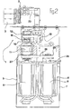
- the two drive stages 5, 6 are common to them Housing 7 arranged side by side.
- the dimensions of the Both drive stages 5, 6 and the two as servomotors trained electric motors 8, 9 of the two drive stages 5, 6 correspond to each other in the radial and axial directions.
- the servomotor 8 of the first drive stage 5, which is shown in FIG. 2 is arranged left in the housing 7, has an output shaft 10, one with the second drive stage 6 in drive connection located hollow shaft 11 in the axial direction at the The distal end is surmounted and rotatable in relation to the hollow shaft 11 is arranged.
- a drive gear 12 which in the embodiment shown in Figures 1 to 3 the pushing device 1 via a toothed belt 13 with output gears 14 and 15 in drive connection stands.
- Each of the two driven gears 14, 15 is non-rotatable with a shaft journal 17 and 18 connected.
- Each of the two Shaft 17, 18 has a crank arm 19 and 20, respectively the rotation of the shaft journal 17, 18 a pouring movement performs.
- the two crank arms 19, 20 are at their shaft journal distal ends provided with pivots 21, the rotatably support corresponding bearing sleeves 22 of actuating arms 23, firmly with the sliding member 2 and thus the push fingers 3 are connected.
- the second drive stage 6 of the drive device 5 To generate the pivoting movement of the carrier 16 is the second drive stage 6 of the drive device 5, 6.
- An output shaft 24 of the electric motor 9 of the second drive stage 6 carries at its free end a drive gear 25, the over a toothed belt 26 with a driven gear 27 in drive connection stands, rotatably on the of the output shaft 10 of the electric motor 8 of the first drive stage penetrated Hollow shaft 11 is seated.
- the hollow shaft 11 is thus by means of second drive stage 6 can be acted upon by a rotational movement.
- the hollow shaft 11 At its end opposite to the output gear 27 end is the hollow shaft 11 rotatably connected to the carrier 16.
- the Hollow shaft 11 is arranged eccentrically with respect to the carrier 16, so that by means of a rotation of the hollow shaft 11 in the a direction of the carrier 16 in a corresponding direction is pivotable, wherein a rotation of the hollow shaft 11 in the another direction, a pivoting of the carrier 16 in the corresponding has opposite direction result.
- the carrier 16 is by means of the second drive stage of the drive device first about 90 degrees in one direction pivoted, and then 90 degrees in the other direction swiveled until it returns to its original position.
- the pivoting of the carrier 16 in one direction begins about the moment when the thrust fingers 3 of the Sliding member 2 in contact with the glass articles to be moved devices.
- the pivotal movement of the carrier 16 in the other, opposite direction takes place when the shear fingers of the sliding member 2 after moving the glassware on the conveyor belt out of contact with the glassware are.
- the above-described pusher 1 is present on IS glass machines universally mountable.
- the pusher can be used for all modes of production (SG, DG, TG) and all Center distances (4.25 “, 5", 5.5 “, 6", 6.25 ") used become.
- the same pusher 1 is for LH and RH versions used.
- the pusher 1 includes a control unit directly integrated into a control device of the IS glass machine is. This makes it possible that on the IS glass machine made speed or clock changes immediately and automatically in appropriate adjustments and changes in the movement of the pusher 1 or the operation of the two drive stages 5, 6 thereof be implemented. For reasons of operational safety is the Control unit of the pusher 1 with an electronic Torque limiting for the drive means 5, 6 provided.
- the control unit is further assigned a touch screen, by means of a user-friendly operation of the control unit is possible.
Landscapes
- Engineering & Computer Science (AREA)
- Chemical & Material Sciences (AREA)
- Manufacturing & Machinery (AREA)
- Materials Engineering (AREA)
- Organic Chemistry (AREA)
- Special Conveying (AREA)
Abstract
Description
Die Erfindung bezieht sich auf eine Schubvorrichtung zur Überführung von Glasartikeln von einer Station einer IS-Glasmaschine auf ein Fördermittel, mit einem Verschiebeglied, das in Anlage an die zu überführenden Glasartikel bringbar und mittels dem die Glasartikel von der Station auf das Fördermittel stellbar sind, Stellteilen, die unmittelbar mit dem Verschiebeglied verbunden sind, und einer Antriebsvorrichtung, mittels der das Verschiebeglied über die Stellteile antreibbar ist.The invention relates to a pushing device for Transfer of glass articles from a station of an IS glass machine on a grant, with a shift member, that can be brought into contact with the glassware to be transferred and by means of which the glass articles from the station onto the conveyor are adjustable, adjusting directly with the Displacement member are connected, and a drive device, by means of the sliding member on the actuators is drivable.
Bei der Überführung von Glasartikeln von der Station der IS-Glasmaschine, wobei die Glasartikel eine Temperatur von 600 bis 700 Grad C aufweisen, kommt es aufgrund mangelnder Synchronisierung zwischen der Bewegung der Schubvorrichtung und der Bewegung der die Glasartikel aufnehmenden Fördereinrichtung vergleichsweise häufig dazu, dass die Glasartikel beschädigt werden. Hierdurch wird in unerwünschter Weise der Ausschuss erhöht, wobei darüber hinaus aufgrund etwaig zerstörter Glasartikel Störungen im Betriebsablauf auftreten können. During the transfer of glass articles from the station of the IS glass machine, the glass articles having a temperature of 600 up to 700 degrees C, it comes due to lack of synchronization between the movement of the pusher and the movement of the glass article receiving conveyor comparatively often causes the glassware to be damaged become. This will undesirably the In addition, due to possibly destroyed Glassware malfunctions occur in the operation can.
Der Erfindung liegt die Aufgabe zugrunde, eine Schubvorrichtung zur Überführung von Glasartikeln von einer Station einer IS-Glasmaschine auf ein Fördermittel der eingangs geschilderten Art zu schaffen, deren Bewegungsablauf mehr oder weniger synchron in Bezug auf das Fördermittel ist und somit einen sicheren Transport der Glasartikel von der betreffenden Station der IS-Glasmaschine zum Fördermittel gewährleistet.The invention is based on the object, a pusher for the transfer of glass articles from a station of a IS glass machine on a conveyor of the initially described Way of creating, their movement more or less is synchronous with respect to the funding and thus one safe transport of glassware from the station concerned the IS glass machine ensures the conveyor.
Diese Aufgabe wird erfindungsgemäß dadurch gelöst, dass die Antriebsvorrichtung eine erste Antriebsstufe, mittels der die unmittelbar mit dem Verschiebeglied verbundenen Stellteile antreibbar sind, und eine zweite Antriebsstufe aufweist, die neben der ersten Antriebsstufe angeordnet ist und mittels der ein die unmittelbar mit dem Verschiebeglied verbundenen Stellteile halternder Träger antreibbar ist. Der Betrieb der beiden die Antriebseinrichtung der erfindungsgemäßen Schubvorrichtung bildenden Antriebsstufen kann so aufeinander abgestimmt werden, dass die Verschiebebewegung der Glasartikel auf das Fördermittel in einer Weise realisiert wird, bei der der Glasartikel bei seinem Übergang auf das Fördermittel bereits mehr oder weniger mit der Geschwindigkeit des Fördermittels sich bewegt. Beschädigungen von mehreren gleichzeitig auf das Förderband verschobenen Glasartikeln können im Falle der erfindungsgemäßen Schubvorrichtung weitestgehend ausgeschlossen werden. Hierdurch wird ein störungsfreierer Betrieb der IS-Glasmaschine und der vor- und nachgeschalteten Anlagen ermöglicht.This object is achieved in that the Drive device, a first drive stage, by means of which directly connected to the shift member actuators are drivable, and has a second drive stage, the is arranged next to the first drive stage and by means of one directly connected to the scroll member Operating parts holding carrier is driven. Operation of the both the drive device of the thrust device according to the invention forming drive stages can thus be coordinated Be that sliding movement of the glassware is realized on the funding in a manner in which the glass article already in its transition to the funding more or less with the speed of the conveyor moves. Damage of several at the same time on the conveyor belt shifted glass articles can in the case the thrust device according to the invention as far as possible excluded become. This is a trouble-free operation the IS glass machine and the upstream and downstream systems allows.
Um eine möglichst genaue Umsetzung der in den Antriebsstufen erzeugten Bewegungsenergien in den Bewegungsablauf des Verschiebeglieds zu gewährleisten, weist die erste Antriebsstufe einen Elektromotor auf, der getriebelos mit einem Antriebsglied der unmittelbar mit dem Verschiebeglied verbundenen Stellteile verbunden ist. Hierdurch kann sichergestellt werden, dass die Antriebsenergie des Elektromotors exakt in den Bewegungsablauf des Verschiebeglieds umgesetzt wird.To achieve the most accurate implementation possible in the drive stages generated kinetic energy in the movement of the displacement member to ensure the first drive stage an electric motor, the gearless with a drive member the directly associated with the displacement member Control parts is connected. This can ensure that the drive power of the electric motor exactly in the Movement of the displacement member is implemented.
Entsprechend kann die zweite Antriebsstufe vorteilhaft einen Elektromotor aufweisen, der getriebelos mit einem Antriebsglied des Trägers verbunden ist, wobei sich analoge Vorteile ergeben.Accordingly, the second drive stage advantageously a Have electric motor, the gearless with a drive member the carrier is connected, with analogous advantages result.
Als besonders vorteilhaft hat es sich erwiesen, wenn der Elektromotor der ersten Antriebsstufe und/oder der Elektromotor der zweiten Antriebsstufe als Servomotor bzw. -motoren ausgebildet ist bzw. sind, da mittels derartiger Servomotoren eine hohe Genauigkeit und Reproduzierbarkeit der durchgeführten Bewegungsabläufe realisiert werden kann.It has proved to be particularly advantageous if the Electric motor of the first drive stage and / or the electric motor the second drive stage as a servomotor or motors is formed or, since by means of such servomotors a high accuracy and reproducibility of the performed Movements can be realized.
Gemäß einer weiteren vorteilhaften Ausführungsform der erfindungsgemäßen Schubvorrichtung sind die am Träger gehalterten Stellteile des Verschiebeglieds mittels der ersten Antriebsstufe während der Überführung eines Glasartikels von der Station zum Fördermittel kontinuierlich in die eine Richtung drehbar und ist der Träger mittels der zweiten Antriebsstufe während der Überführung eines Glasartikels von der Station zum Fördermittel in einer ersten Bewegungsphase in die eine Richtung und in einer zweiten Bewegungsphase in die andere, entgegengesetzte Richtung dreh- bzw. schwenkbar, wobei die Drehung der Stellteile und die Drehung bzw. Schwenkung des Trägers während der beiden Bewegungsphasen desselben einander überlagern. According to a further advantageous embodiment of the invention Pusher are held on the carrier Control parts of the displacement member by means of the first drive stage during the transfer of a glass article from the station to the conveyor continuously in one direction rotatable and is the carrier by means of the second drive stage during the transfer of a glass article from the station to the funding in a first phase of movement in one Direction and in a second phase of movement into the other, opposite direction rotatable or pivotable, the Rotation of the controls and the rotation or pivoting of the Carrier during the two phases of movement of each other overlap.
Eine Abgangswelle des Elektromotors der ersten Antriebsstufe ist zweckmäßigerweise koaxial in einer mittels des Elektromotors der zweiten Antriebsstufe angetriebenen Hohlwelle angeordnet, in Bezug auf diese Hohlwelle rotierbar und sie steht an deren elektromotorfernen Stirnseite durch diese vor, wobei sie an ihrem derart vorstehenden Ende drehfest mit einem das Antriebsglied der unmittelbar mit dem Verschiebeglied verbundenen Stellteile bildenden Antriebszahnrad verbunden ist.An output shaft of the electric motor of the first drive stage is expediently coaxial in one by means of the electric motor the second drive stage driven hollow shaft arranged rotatable with respect to this hollow shaft and it stands at the electric motor remote end face through this before, wherein they rotatably at their so-protruding end with a the Drive member of directly connected to the sliding member Operating parts forming drive gear is connected.
Zweckmäßigerweise treibt das drehfest mit der Abgangswelle des Elektromotors der ersten Antriebstufe verbundene Antriebszahnrad mittels eines Zahnriemens zumindest zwei Abtriebszahnräder an, von denen jedes drehfest mit einem mittels eines Kurbelarms mit dem Verschiebeglied verbundenen Wellenzapfen verbunden ist.Appropriately, rotatably drives the output shaft the drive motor connected to the electric motor of the first drive stage by means of a toothed belt at least two output gears each of which rotates with a means of a crank arm connected to the sliding member Shaft journal is connected.
Der Träger kann vorteilhaft ein Gehäuse für das Antriebszahnrad der ersten Antriebsstufe, den Zahnriemen und die zumindest zwei Abtriebszahnräder ausbilden.The carrier may advantageously be a housing for the drive gear the first drive stage, the timing belt and the at least train two output gears.
Eine Abgangswelle des Elektromotors der zweiten Antriebsstufe ist zweckmäßigerweise entsprechend drehfest mit einem Antriebszahnrad verbunden, das mittels eines Zahnriemens in Antriebsverbindung mit einem drehfest auf der Hohlwelle sitzenden Abtriebszahnrad ist.An output shaft of the electric motor of the second drive stage is expediently correspondingly rotationally fixed with a drive gear connected by means of a toothed belt in drive connection with a non-rotatably seated on the hollow shaft Output gear is.
Die Hohlwelle ihrerseits ist vorteilhaft exzentrisch und drehfest mit dem Träger verbunden, wobei dieser mittels der Hohlwelle entsprechend der Drehrichtung der Abgangswelle des Elektromotors der zweiten Antriebsstufe in die eine bzw. die andere Richtung schwenkbar ist. The hollow shaft in turn is advantageous eccentric and rotatably connected to the carrier, said means of the Hollow shaft according to the direction of rotation of the output shaft of Electric motor of the second drive stage in one or the other direction is pivotable.
Vorteilhaft sind die beiden Antriebsstufen in einem ihnen gemeinsamen Gehäuse angeordnet, wobei beide Antriebsstufen sowohl in ihrer Axial- als auch in ihrer Radialrichtung dieselben Abmessungen aufweisen können.Advantageously, the two drive stages are common to them Housing arranged, both drive stages both in their axial as well as in their radial direction the same Dimensions may have.
Die erfindungsgemäße Schubvorrichtung ist an vorhandene IS-Glasmaschinen universell montierbar, wobei sie sowohl als linke (LH) als auch als rechte (RH) Ausführungsform gestaltbar ist.The thrust device according to the invention is available on existing IS glass machines universally mountable, both as left (LH) as well as right (RH) embodiment shapable is.
Die Steuereinheit der erfindungsgemäßen Schubvorrichtung ist vorteilhaft direkt in eine Steuerungsvorrichtung der IS-Glasmaschine integrierbar, derart, dass Geschwindigkeits- bzw. Taktänderungen der IS-Glasmaschine unmittelbar und automatisch in dementsprechende Anpassungen und Änderungen des Bewegungsablaufs der Schubvorrichtung resultieren, wobei die Anpassung bzw. Änderung des Bewegungsablaufs durch entsprechende Eingriffe in die Steuerung der ersten und der zweiten Antriebsstufe der Antriebsvorrichtung realisiert werden können.The control unit of the pusher according to the invention is advantageously directly into a control device of the IS glass machine integrable such that speed or clock changes of the IS glass machine directly and automatically in corresponding adjustments and changes of the Movement of the pusher result, the Adaptation or change of the movement through appropriate Intervention in the control of the first and the second Drive stage of the drive device can be realized.
Aus Gründen der Betriebssicherheit ist es zweckmäßig, wenn die Schubvorrichtung eine elektronische Drehkraftbegrenzung für die erste und/oder die zweite Antriebsstufe aufweist.For reasons of operational safety, it is expedient if the pusher an electronic torque limit for the first and / or the second drive stage.
Zur Vereinfachung der Bedienung kann die Steuereinheit der erfindungsgemäßen Schubvorrichtung als Eingabeelemente Touch-Screens aufweisen.To simplify the operation, the control unit of inventive push device as input elements touch screens exhibit.
Im folgenden wird die Erfindung anhand einer Ausführungsform unter Bezugnahme auf die Zeichnung näher erläutert. In the following the invention with reference to an embodiment explained in more detail with reference to the drawing.
Es zeigen:
Figur 1- eine perspektivische Darstellung einer Ausführungsform der erfindungsgemäßen Schubvorrichtung zur Überführung von Glasartikeln von einer Station einer IS-Glasmaschine auf ein Fördermittel;
Figur 2- einen Längsschnitt durch die in
Figur 1 gezeigte Ausführungsform der erfindungsgemäßen Schubvorrichtung; und Figur 3- einen Querschnitt durch die in
Figur 1 gezeigte Ausführungsform der erfindungsgemäßen Schubvorrichtung.
- FIG. 1
- a perspective view of an embodiment of the invention thrust device for transferring glass articles from a station of an IS glass machine on a conveyor;
- FIG. 2
- a longitudinal section through the embodiment of the thrust device according to the invention shown in Figure 1; and
- FIG. 3
- a cross section through the embodiment shown in Figure 1 of the thrust device according to the invention.
Eine anhand der Figuren 1 bis 3 dargestellte Ausführungsform
einer erfindungsgemäßen Schubvorrichtung 1 dient dazu, Glasartikel,
die 600 bis 700 Grad C heiß sind, aus einer Station
einer IS-Glasmaschine auf ein Fördermittel, z.B. ein Transportband,
zu schieben, mittels dem die Glasartikel von der
betreffenden Station der IS-Glasmaschine entfernt werden.An embodiment shown with reference to FIGS. 1 to 3
a pushing
Zu der Schubvorrichtung 1 gehört ein Verschiebeglied 2 mit
Schubfingern 3, die, wie sich am besten aus Figur 1 ergibt,
gebogen und geteilt ausgebildet sein können, um einen besseren
Zugriff auf die zu verschiebenden Glasartikel ausüben zu
können. Mittels verstellbarer Fixiereinrichtungen 4 kann das
Verschiebeglied 2 an unterschiedliche Abmessungen aufweisende,
zu verschiebende Glasartikel angepasst werden.To the
Die zur Durchführung der Verschiebung erforderliche Bewegung
des Verschiebeglieds 2 bzw. der Schubfinger 3 wird durch eine
Antriebsvorrichtung 5, 6 erzeugt, zu der eine erste Antriebsstufe
5 und eine zweite Antriebsstufe 6 gehören. The movement required to make the shift
of the sliding
Die beiden Antriebsstufen 5, 6 sind in einem ihnen gemeinsamen
Gehäuse 7 nebeneinander angeordnet. Die Abmessungen der
beiden Antriebsstufen 5, 6 bzw. der beiden als Servomotoren
ausgebildeten Elektromotoren 8, 9 der beiden Antriebsstufen
5, 6 entsprechen einander in Radial- und in Axialrichtung.The two
Der Servomotor 8 der ersten Antriebsstufe 5, der in Figur 2
links im Gehäuse 7 angeordnet ist, hat eine Abgangswelle 10,
die eine mit der zweiten Antriebsstufe 6 in Antriebsverbindung
befindliche Hohlwelle 11 in Axialrichtung an deren
distaler Stirnseite überragt und die rotierbar in Bezug auf
die Hohlwelle 11 angeordnet ist. An ihrem die Hohlwelle 11
durchragenden Endabschnitt trägt die Abgangswelle 10 des
Elektromotors 8 der ersten Antriebsstufe 5 ein Antriebszahnrad
12, welches im in den Figuren 1 bis 3 dargestellten Ausführungsbeispiel
der Schubvorrichtung 1 über einen Zahnriemen
13 mit Abtriebszahnrädern 14 und 15 in Antriebsverbindung
steht.The
Das von der Abgangswelle 10 des Elektromotors 8 der ersten
Antriebsstufe angetriebene Antriebszahnrad 12, der dieses umschlingende
Zahnriemen 13 sowie die über den Zahnriemen 13
mit dem Antriebszahnrad 12 in Antriebsverbindung stehenden
Abtriebszahnräder 14, 15 sind an bzw. in einem als Gehäuse
ausgebildeten Träger 16 gelagert.That of the
Jedes der beiden Abtriebszahnräder 14, 15 ist drehfest mit
einem Wellenzapfen 17 bzw. 18 verbunden. Jeder der beiden
Wellenzapfen 17, 18 hat einen Kurbelarm 19 bzw. 20, der entsprechend
der Drehung des Wellenzapfens 17, 18 eine Schenkbewegung
ausführt. Die beiden Kurbelarme 19, 20 sind an ihren
wellenzapfenfernen Enden mit Drehzapfen 21 versehen, die
drehbar entsprechende Lagerhülsen 22 von Stellarmen 23 lagern,
die fest mit dem Verschiebeglied 2 und damit den Schubfingern
3 verbunden sind.Each of the two driven
Mit den vorstehend erwähnten Wellenzapfen 17, 18, Kurbelarmen
19, 20, Drehzapfen 21, Lagerhülsen 22 und Stellarmen 23 wird
die auf die Wellenzapfen 17, 18 übertragene Rotationsbewegung
der Abgangswelle 10 der ersten Antriebsstufe 5 in eine
Schwenkbewegung des Verschiebeglieds 2 bzw. der an diesem
vorgesehenen Schubfinger 3 umgesetzt, die Teil desjenigen Bewegungsablaufs
ist, mittels dem die Glasartikel auf das Förderband
verschoben werden. Eine weitere Komponente dieses Bewegungsablaufs
wird mittels einer Schwenkbewegung des Trägers
16 realisiert, in Bezug auf den die Wellenzapfen 17, 18 ortsfest
angeordnet sind.With the above-mentioned
Zur Erzeugung der Schwenkbewegung des Trägers 16 dient die
zweite Antriebsstufe 6 der Antriebseinrichtung 5, 6. Eine Abgangswelle
24 des Elektromotors 9 der zweiten Antriebsstufe 6
trägt an ihrem freien Ende ein Antriebszahnrad 25, das über
einen Zahnriemen 26 mit einem Abtriebszahnrad 27 in Antriebsverbindung
steht, das drehfest auf der von der Abgangswelle
10 des Elektromotors 8 der ersten Antriebsstufe durchragten
Hohlwelle 11 sitzt. Die Hohlwelle 11 ist somit mittels der
zweiten Antriebsstufe 6 mit einer Rotationsbewegung beaufschlagbar.To generate the pivoting movement of the
An ihrem zum Abtriebszahnrad 27 entgegengesetzten Ende ist
die Hohlwelle 11 drehfest mit dem Träger 16 verbunden. Die
Hohlwelle 11 ist in Bezug auf den Träger 16 exzentrisch angeordnet,
so dass mittels einer Drehung der Hohlwelle 11 in der
einen Richtung der Träger 16 in eine entsprechende Richtung
schwenkbar ist, wobei eine Drehung der Hohlwelle 11 in die
andere Richtung eine Schwenkung des Trägers 16 in die entsprechend
entgegengesetzte Richtung zur Folge hat.At its end opposite to the
Bei einer Verschiebung von Glasartikeln auf das Transportband
führen die fest mit den Wellenzapfen 17, 18 verbundenen Kurbelarme
19, 20 eine Drehung bzw. Schwenkung von 360 Grad aus,
bis sie ihre Ausgangsposition wieder erreichen.With a shift of glass articles on the conveyor belt
lead the firmly connected to the
Der Träger 16 wird mittels der zweiten Antriebsstufe der Antriebseinrichtung
zunächst um ca. 90 Grad in die eine Richtung
verschwenkt, und danach um 90 Grad in die andere Richtung
verschwenkt, bis er seine Ausgangsposition wieder einnimmt.
Die Verschwenkung des Trägers 16 in die eine Richtung
beginnt etwa in dem Augenblick, wenn die Schubfinger 3 des
Verschiebeglieds 2 in Anlage an die zu verschiebenden Glasartikel
geraten. Die Schwenkbewegung des Trägers 16 in die andere,
entgegengesetzte Richtung findet statt, wenn die Schubfinger
des Verschiebeglieds 2 nach dem Verschieben der Glasartikel
auf das Förderband außer Anlage mit den Glasartikeln
sind.The
Die vorstehend geschilderte Schubvorrichtung 1 ist an vorhandene
IS-Glasmaschinen universell montierbar. Die Schubvorrichtung
kann für alle Produktionsweisen (SG, DG, TG) und alle
Mittenabstände (4,25", 5", 5,5", 6", 6,25") eingesetzt
werden. Die gleiche Schubvorrichtung 1 ist für LH- und RH-Ausführungen
einsetzbar.The above-described
Zur Schubvorrichtung 1 gehört eine Steuereinheit, die direkt
in eine Steuerungsvorrichtung der IS-Glasmaschine integrierbar
ist. Hierdurch ist es möglich, dass an der IS-Glasmaschine
vorgenommene Geschwindigkeits- bzw. Taktänderungen
unmittelbar und automatisch in dementsprechende Anpassungen
und Änderungen des Bewegungsablaufs der Schubvorrichtung
1 bzw. des Betriebs der beiden Antriebsstufen 5, 6 derselben
umgesetzt werden. Aus Gründen der Betriebssicherheit ist die
Steuereinheit der Schubvorrichtung 1 mit einer elektronischen
Drehkraftbegrenzung für die Antriebseinrichtung 5, 6 versehen.The
Der Steuereinheit ist des weiteren ein Touch-Screen zugeordnet, mittels dem eine benutzerfreundliche Bedienung der Steuereinheit möglich ist.The control unit is further assigned a touch screen, by means of a user-friendly operation of the control unit is possible.
Claims (17)
Applications Claiming Priority (2)
| Application Number | Priority Date | Filing Date | Title |
|---|---|---|---|
| DE102004013518 | 2004-03-19 | ||
| DE200410013518 DE102004013518B4 (en) | 2004-03-19 | 2004-03-19 | Pusher for transferring glass articles from a station of an IS glass machine to a conveyor |
Publications (3)
| Publication Number | Publication Date |
|---|---|
| EP1577271A2 true EP1577271A2 (en) | 2005-09-21 |
| EP1577271A3 EP1577271A3 (en) | 2006-01-11 |
| EP1577271B1 EP1577271B1 (en) | 2013-04-10 |
Family
ID=34833193
Family Applications (1)
| Application Number | Title | Priority Date | Filing Date |
|---|---|---|---|
| EP20050000216 Expired - Lifetime EP1577271B1 (en) | 2004-03-19 | 2005-01-07 | Transfer mechanism for glass articles from a station of an IS machine to a conveyor |
Country Status (2)
| Country | Link |
|---|---|
| EP (1) | EP1577271B1 (en) |
| DE (1) | DE102004013518B4 (en) |
Cited By (4)
| Publication number | Priority date | Publication date | Assignee | Title |
|---|---|---|---|---|
| EP1627858A1 (en) * | 2004-08-18 | 2006-02-22 | BOTTERO S.p.A. | Transfer apparatus for transferring glass articles |
| EP1627859A1 (en) * | 2004-08-18 | 2006-02-22 | BOTTERO S.p.A. | Transfer apparatus for transferring glass articles |
| RU2435737C2 (en) * | 2006-02-10 | 2011-12-10 | Эмхарт Гласс С.А. | Extracting mechanism for machine with separate sections |
| GB2637293A (en) * | 2023-12-21 | 2025-07-23 | Anglo Carbon & Contacts Ltd | Article handling apparatus |
Citations (3)
| Publication number | Priority date | Publication date | Assignee | Title |
|---|---|---|---|---|
| CZ304796A3 (en) | 1996-10-17 | 1998-06-17 | Sklostroj-Sklářské Strojírny Turnov S. R. O. | Downtime mechanism of glass forming machine |
| US20050193773A1 (en) | 2004-03-03 | 2005-09-08 | Heye International Gmbh | Process and device for pushing hollow glass objects from a glass forming machine onto a conveyor belt |
| US20050199011A1 (en) | 2004-03-12 | 2005-09-15 | Heye International Gmbh | Device for transferring hollow glass objects from a glass-forming machine onto a conveyor belt |
Family Cites Families (8)
| Publication number | Priority date | Publication date | Assignee | Title |
|---|---|---|---|---|
| JPS63139022A (en) * | 1986-11-29 | 1988-06-10 | Nippon Taisanbin Kogyo Kk | Pusher device of bottle making machine |
| GB9023103D0 (en) * | 1990-10-24 | 1990-12-05 | Emhart Ind | Push out device for a glassware forming machine |
| DE4231454C2 (en) * | 1992-09-19 | 1995-06-22 | Gps Glasprod Serv Gmbh | Delivery station for an IS glass molding machine |
| ES2097687B1 (en) * | 1993-07-05 | 1998-03-16 | Avacon Sa | PERFECTED BOTTLE PUNCHER FOR HOLLOW GLASS MOLDING MACHINES. |
| DE19500787C1 (en) * | 1995-01-13 | 1995-11-23 | Heye Hermann Fa | Hollow glass moulding machine |
| US5818190A (en) * | 1997-05-16 | 1998-10-06 | Emhart Glass Machinery Investments Inc. | Programmable electronic clutch for I.S. machine |
| DE29902149U1 (en) * | 1999-02-06 | 1999-08-05 | Fa. Hermann Heye, 31683 Obernkirchen | Device for pushing hollow glass objects onto a conveyor belt |
| CZ296596B6 (en) * | 2004-03-02 | 2006-04-12 | Sklostroj Turnov Cz, S. R. O. | Dead plate mechanism of glass forming machine |
-
2004
- 2004-03-19 DE DE200410013518 patent/DE102004013518B4/en not_active Expired - Fee Related
-
2005
- 2005-01-07 EP EP20050000216 patent/EP1577271B1/en not_active Expired - Lifetime
Patent Citations (3)
| Publication number | Priority date | Publication date | Assignee | Title |
|---|---|---|---|---|
| CZ304796A3 (en) | 1996-10-17 | 1998-06-17 | Sklostroj-Sklářské Strojírny Turnov S. R. O. | Downtime mechanism of glass forming machine |
| US20050193773A1 (en) | 2004-03-03 | 2005-09-08 | Heye International Gmbh | Process and device for pushing hollow glass objects from a glass forming machine onto a conveyor belt |
| US20050199011A1 (en) | 2004-03-12 | 2005-09-15 | Heye International Gmbh | Device for transferring hollow glass objects from a glass-forming machine onto a conveyor belt |
Cited By (6)
| Publication number | Priority date | Publication date | Assignee | Title |
|---|---|---|---|---|
| EP1627858A1 (en) * | 2004-08-18 | 2006-02-22 | BOTTERO S.p.A. | Transfer apparatus for transferring glass articles |
| EP1627859A1 (en) * | 2004-08-18 | 2006-02-22 | BOTTERO S.p.A. | Transfer apparatus for transferring glass articles |
| US7264108B2 (en) | 2004-08-18 | 2007-09-04 | Bottero S.P.A. | Transfer unit for transferring glass articles |
| US7325668B2 (en) | 2004-08-18 | 2008-02-05 | Bottero S.P.A. | Transfer unit for transferring glass articles |
| RU2435737C2 (en) * | 2006-02-10 | 2011-12-10 | Эмхарт Гласс С.А. | Extracting mechanism for machine with separate sections |
| GB2637293A (en) * | 2023-12-21 | 2025-07-23 | Anglo Carbon & Contacts Ltd | Article handling apparatus |
Also Published As
| Publication number | Publication date |
|---|---|
| EP1577271B1 (en) | 2013-04-10 |
| DE102004013518B4 (en) | 2006-06-14 |
| DE102004013518A1 (en) | 2005-10-13 |
| EP1577271A3 (en) | 2006-01-11 |
Similar Documents
| Publication | Publication Date | Title |
|---|---|---|
| DE2727101C3 (en) | Device for the synchronous pivoting of panels, especially for solar cells | |
| DE602005000347T2 (en) | Power transmission device and plate-shaped material supply device containing the same | |
| DE3831412A1 (en) | DEVICE FOR FOLDING A PAPERBOARD OR THE LIKE | |
| DE3526846C2 (en) | ||
| EP1577271B1 (en) | Transfer mechanism for glass articles from a station of an IS machine to a conveyor | |
| DE102009006044B4 (en) | handling modules | |
| DE102004013519B4 (en) | Pusher for transferring glass articles from a station of an IS glass machine to a conveyor | |
| EP1099501A1 (en) | High speed shearing machine for cutting rolled stock | |
| DE2231955A1 (en) | INSTALLATION AND PROCEDURE FOR TRANSFERRING COLLECTED SIGNATURES | |
| EP1002596B1 (en) | Apparatus for stepwise transport of a strip | |
| EP1767475B1 (en) | Device for pushing articles from a conveyor belt to another | |
| EP1068040A1 (en) | High speed shearing machine for hot cutting of band iron | |
| DE10315822A1 (en) | Rotatable signature transfer device | |
| DD301692A9 (en) | AUTOMATIC PACKAGING MACHINE, ESPECIALLY FOR THE MANUFACTURE OF PACKAGING FOR FLOWER PACK PATTERNS | |
| EP0254847B1 (en) | Driving device for the front grippers of a printing machine | |
| EP0188648B1 (en) | Transfer press | |
| DE102004011978A1 (en) | Saddle stitcher with two working shafts | |
| DE4033437A1 (en) | THREE-KNIFE CUTTING MACHINE | |
| EP1720785B1 (en) | Folding device for folding printed products | |
| DE102013213303A1 (en) | Electric switch with conversion of a rotary motion into an oscillating movement of a switch component | |
| DE1952938C3 (en) | Method for embossing a flat object and device for carrying out this method | |
| DE10233884A1 (en) | Tool changing system for machine tool has grip arm and movement device driven synchronously from common drive | |
| EP1818300A1 (en) | Transverse folding section of a folding apparatus of a printing press | |
| DE102009015143B4 (en) | Cutting device and associated method for shortening component belts | |
| DE2350458B2 (en) | MACHINE FOR LINING LOOSELY SUPPLIED ELECTRICAL COMPONENTS |
Legal Events
| Date | Code | Title | Description |
|---|---|---|---|
| PUAI | Public reference made under article 153(3) epc to a published international application that has entered the european phase |
Free format text: ORIGINAL CODE: 0009012 |
|
| AK | Designated contracting states |
Kind code of ref document: A2 Designated state(s): AT BE BG CH CY CZ DE DK EE ES FI FR GB GR HU IE IS IT LI LT LU MC NL PL PT RO SE SI SK TR |
|
| AX | Request for extension of the european patent |
Extension state: AL BA HR LV MK YU |
|
| PUAL | Search report despatched |
Free format text: ORIGINAL CODE: 0009013 |
|
| AK | Designated contracting states |
Kind code of ref document: A3 Designated state(s): AT BE BG CH CY CZ DE DK EE ES FI FR GB GR HU IE IS IT LI LT LU MC NL PL PT RO SE SI SK TR |
|
| AX | Request for extension of the european patent |
Extension state: AL BA HR LV MK YU |
|
| 17P | Request for examination filed |
Effective date: 20060127 |
|
| 17Q | First examination report despatched |
Effective date: 20060626 |
|
| AKX | Designation fees paid |
Designated state(s): AT BE BG CH CY CZ DE DK EE ES FI FR GB GR HU IE IS IT LI LT LU MC NL PL PT RO SE SI SK TR |
|
| GRAP | Despatch of communication of intention to grant a patent |
Free format text: ORIGINAL CODE: EPIDOSNIGR1 |
|
| GRAS | Grant fee paid |
Free format text: ORIGINAL CODE: EPIDOSNIGR3 |
|
| GRAA | (expected) grant |
Free format text: ORIGINAL CODE: 0009210 |
|
| AK | Designated contracting states |
Kind code of ref document: B1 Designated state(s): AT BE BG CH CY CZ DE DK EE ES FI FR GB GR HU IE IS IT LI LT LU MC NL PL PT RO SE SI SK TR |
|
| REG | Reference to a national code |
Ref country code: GB Ref legal event code: FG4D Free format text: NOT ENGLISH Ref country code: DE Ref legal event code: R081 Ref document number: 502005013612 Country of ref document: DE Owner name: ROLF THEMANN & PARTNER SA, LU Free format text: FORMER OWNER: GPS GLASPRODUKTIONS-SERVICE GMBH, 45329 ESSEN, DE |
|
| REG | Reference to a national code |
Ref country code: AT Ref legal event code: REF Ref document number: 605900 Country of ref document: AT Kind code of ref document: T Effective date: 20130415 Ref country code: CH Ref legal event code: EP |
|
| REG | Reference to a national code |
Ref country code: IE Ref legal event code: FG4D Free format text: LANGUAGE OF EP DOCUMENT: GERMAN |
|
| REG | Reference to a national code |
Ref country code: DE Ref legal event code: R096 Ref document number: 502005013612 Country of ref document: DE Effective date: 20130606 |
|
| REG | Reference to a national code |
Ref country code: SE Ref legal event code: TRGR |
|
| PG25 | Lapsed in a contracting state [announced via postgrant information from national office to epo] |
Ref country code: SI Free format text: LAPSE BECAUSE OF FAILURE TO SUBMIT A TRANSLATION OF THE DESCRIPTION OR TO PAY THE FEE WITHIN THE PRESCRIBED TIME-LIMIT Effective date: 20130410 |
|
| REG | Reference to a national code |
Ref country code: LT Ref legal event code: MG4D Ref country code: NL Ref legal event code: VDEP Effective date: 20130410 |
|
| PG25 | Lapsed in a contracting state [announced via postgrant information from national office to epo] |
Ref country code: PT Free format text: LAPSE BECAUSE OF FAILURE TO SUBMIT A TRANSLATION OF THE DESCRIPTION OR TO PAY THE FEE WITHIN THE PRESCRIBED TIME-LIMIT Effective date: 20130812 Ref country code: NL Free format text: LAPSE BECAUSE OF FAILURE TO SUBMIT A TRANSLATION OF THE DESCRIPTION OR TO PAY THE FEE WITHIN THE PRESCRIBED TIME-LIMIT Effective date: 20130410 Ref country code: IS Free format text: LAPSE BECAUSE OF FAILURE TO SUBMIT A TRANSLATION OF THE DESCRIPTION OR TO PAY THE FEE WITHIN THE PRESCRIBED TIME-LIMIT Effective date: 20130810 Ref country code: GR Free format text: LAPSE BECAUSE OF FAILURE TO SUBMIT A TRANSLATION OF THE DESCRIPTION OR TO PAY THE FEE WITHIN THE PRESCRIBED TIME-LIMIT Effective date: 20130711 Ref country code: FI Free format text: LAPSE BECAUSE OF FAILURE TO SUBMIT A TRANSLATION OF THE DESCRIPTION OR TO PAY THE FEE WITHIN THE PRESCRIBED TIME-LIMIT Effective date: 20130410 Ref country code: ES Free format text: LAPSE BECAUSE OF FAILURE TO SUBMIT A TRANSLATION OF THE DESCRIPTION OR TO PAY THE FEE WITHIN THE PRESCRIBED TIME-LIMIT Effective date: 20130721 Ref country code: LT Free format text: LAPSE BECAUSE OF FAILURE TO SUBMIT A TRANSLATION OF THE DESCRIPTION OR TO PAY THE FEE WITHIN THE PRESCRIBED TIME-LIMIT Effective date: 20130410 |
|
| PG25 | Lapsed in a contracting state [announced via postgrant information from national office to epo] |
Ref country code: CY Free format text: LAPSE BECAUSE OF FAILURE TO SUBMIT A TRANSLATION OF THE DESCRIPTION OR TO PAY THE FEE WITHIN THE PRESCRIBED TIME-LIMIT Effective date: 20130410 Ref country code: BG Free format text: LAPSE BECAUSE OF FAILURE TO SUBMIT A TRANSLATION OF THE DESCRIPTION OR TO PAY THE FEE WITHIN THE PRESCRIBED TIME-LIMIT Effective date: 20130710 Ref country code: PL Free format text: LAPSE BECAUSE OF FAILURE TO SUBMIT A TRANSLATION OF THE DESCRIPTION OR TO PAY THE FEE WITHIN THE PRESCRIBED TIME-LIMIT Effective date: 20130410 |
|
| PG25 | Lapsed in a contracting state [announced via postgrant information from national office to epo] |
Ref country code: SK Free format text: LAPSE BECAUSE OF FAILURE TO SUBMIT A TRANSLATION OF THE DESCRIPTION OR TO PAY THE FEE WITHIN THE PRESCRIBED TIME-LIMIT Effective date: 20130410 Ref country code: DK Free format text: LAPSE BECAUSE OF FAILURE TO SUBMIT A TRANSLATION OF THE DESCRIPTION OR TO PAY THE FEE WITHIN THE PRESCRIBED TIME-LIMIT Effective date: 20130410 Ref country code: EE Free format text: LAPSE BECAUSE OF FAILURE TO SUBMIT A TRANSLATION OF THE DESCRIPTION OR TO PAY THE FEE WITHIN THE PRESCRIBED TIME-LIMIT Effective date: 20130410 |
|
| PLBE | No opposition filed within time limit |
Free format text: ORIGINAL CODE: 0009261 |
|
| STAA | Information on the status of an ep patent application or granted ep patent |
Free format text: STATUS: NO OPPOSITION FILED WITHIN TIME LIMIT |
|
| PG25 | Lapsed in a contracting state [announced via postgrant information from national office to epo] |
Ref country code: RO Free format text: LAPSE BECAUSE OF FAILURE TO SUBMIT A TRANSLATION OF THE DESCRIPTION OR TO PAY THE FEE WITHIN THE PRESCRIBED TIME-LIMIT Effective date: 20130410 |
|
| 26N | No opposition filed |
Effective date: 20140113 |
|
| REG | Reference to a national code |
Ref country code: DE Ref legal event code: R097 Ref document number: 502005013612 Country of ref document: DE Effective date: 20140113 |
|
| BERE | Be: lapsed |
Owner name: GPS GLASPRODUKTIONS-SERVICE G.M.B.H. Effective date: 20140131 |
|
| PG25 | Lapsed in a contracting state [announced via postgrant information from national office to epo] |
Ref country code: MC Free format text: LAPSE BECAUSE OF FAILURE TO SUBMIT A TRANSLATION OF THE DESCRIPTION OR TO PAY THE FEE WITHIN THE PRESCRIBED TIME-LIMIT Effective date: 20130410 Ref country code: LU Free format text: LAPSE BECAUSE OF FAILURE TO SUBMIT A TRANSLATION OF THE DESCRIPTION OR TO PAY THE FEE WITHIN THE PRESCRIBED TIME-LIMIT Effective date: 20140107 |
|
| GBPC | Gb: european patent ceased through non-payment of renewal fee |
Effective date: 20140107 |
|
| REG | Reference to a national code |
Ref country code: IE Ref legal event code: MM4A |
|
| PG25 | Lapsed in a contracting state [announced via postgrant information from national office to epo] |
Ref country code: GB Free format text: LAPSE BECAUSE OF NON-PAYMENT OF DUE FEES Effective date: 20140107 |
|
| PG25 | Lapsed in a contracting state [announced via postgrant information from national office to epo] |
Ref country code: BE Free format text: LAPSE BECAUSE OF NON-PAYMENT OF DUE FEES Effective date: 20140131 Ref country code: IE Free format text: LAPSE BECAUSE OF NON-PAYMENT OF DUE FEES Effective date: 20140107 |
|
| REG | Reference to a national code |
Ref country code: AT Ref legal event code: MM01 Ref document number: 605900 Country of ref document: AT Kind code of ref document: T Effective date: 20140107 |
|
| PG25 | Lapsed in a contracting state [announced via postgrant information from national office to epo] |
Ref country code: AT Free format text: LAPSE BECAUSE OF NON-PAYMENT OF DUE FEES Effective date: 20140107 |
|
| REG | Reference to a national code |
Ref country code: FR Ref legal event code: PLFP Year of fee payment: 12 |
|
| REG | Reference to a national code |
Ref country code: DE Ref legal event code: R082 Ref document number: 502005013612 Country of ref document: DE Representative=s name: PATENTANWAELTE SPALTHOFF UND LELGEMANN, DE Ref country code: DE Ref legal event code: R081 Ref document number: 502005013612 Country of ref document: DE Owner name: ROLF THEMANN & PARTNER SA, LU Free format text: FORMER OWNER: GPS GLASPRODUKTIONS-SERVICE GMBH, 45329 ESSEN, DE |
|
| PG25 | Lapsed in a contracting state [announced via postgrant information from national office to epo] |
Ref country code: HU Free format text: LAPSE BECAUSE OF FAILURE TO SUBMIT A TRANSLATION OF THE DESCRIPTION OR TO PAY THE FEE WITHIN THE PRESCRIBED TIME-LIMIT; INVALID AB INITIO Effective date: 20050107 Ref country code: TR Free format text: LAPSE BECAUSE OF FAILURE TO SUBMIT A TRANSLATION OF THE DESCRIPTION OR TO PAY THE FEE WITHIN THE PRESCRIBED TIME-LIMIT Effective date: 20130410 |
|
| REG | Reference to a national code |
Ref country code: FR Ref legal event code: PLFP Year of fee payment: 13 |
|
| REG | Reference to a national code |
Ref country code: FR Ref legal event code: PLFP Year of fee payment: 14 |
|
| PGFP | Annual fee paid to national office [announced via postgrant information from national office to epo] |
Ref country code: SE Payment date: 20190124 Year of fee payment: 15 |
|
| REG | Reference to a national code |
Ref country code: SE Ref legal event code: EUG |
|
| REG | Reference to a national code |
Ref country code: SE Ref legal event code: EUG |
|
| PG25 | Lapsed in a contracting state [announced via postgrant information from national office to epo] |
Ref country code: SE Free format text: LAPSE BECAUSE OF NON-PAYMENT OF DUE FEES Effective date: 20200108 |
|
| PGFP | Annual fee paid to national office [announced via postgrant information from national office to epo] |
Ref country code: DE Payment date: 20220318 Year of fee payment: 18 |
|
| PGFP | Annual fee paid to national office [announced via postgrant information from national office to epo] |
Ref country code: CZ Payment date: 20221228 Year of fee payment: 19 |
|
| PGFP | Annual fee paid to national office [announced via postgrant information from national office to epo] |
Ref country code: FR Payment date: 20230123 Year of fee payment: 19 Ref country code: CH Payment date: 20230130 Year of fee payment: 19 |
|
| PGFP | Annual fee paid to national office [announced via postgrant information from national office to epo] |
Ref country code: IT Payment date: 20230131 Year of fee payment: 19 |
|
| REG | Reference to a national code |
Ref country code: DE Ref legal event code: R119 Ref document number: 502005013612 Country of ref document: DE |
|
| PG25 | Lapsed in a contracting state [announced via postgrant information from national office to epo] |
Ref country code: DE Free format text: LAPSE BECAUSE OF NON-PAYMENT OF DUE FEES Effective date: 20230801 |
|
| PG25 | Lapsed in a contracting state [announced via postgrant information from national office to epo] |
Ref country code: CZ Free format text: LAPSE BECAUSE OF NON-PAYMENT OF DUE FEES Effective date: 20240107 |
|
| PG25 | Lapsed in a contracting state [announced via postgrant information from national office to epo] |
Ref country code: CZ Free format text: LAPSE BECAUSE OF NON-PAYMENT OF DUE FEES Effective date: 20240107 |
|
| REG | Reference to a national code |
Ref country code: CH Ref legal event code: PL |
|
| PG25 | Lapsed in a contracting state [announced via postgrant information from national office to epo] |
Ref country code: FR Free format text: LAPSE BECAUSE OF NON-PAYMENT OF DUE FEES Effective date: 20240131 |
|
| PG25 | Lapsed in a contracting state [announced via postgrant information from national office to epo] |
Ref country code: CH Free format text: LAPSE BECAUSE OF NON-PAYMENT OF DUE FEES Effective date: 20240131 |
|
| PG25 | Lapsed in a contracting state [announced via postgrant information from national office to epo] |
Ref country code: FR Free format text: LAPSE BECAUSE OF NON-PAYMENT OF DUE FEES Effective date: 20240131 Ref country code: CH Free format text: LAPSE BECAUSE OF NON-PAYMENT OF DUE FEES Effective date: 20240131 |
|
| PG25 | Lapsed in a contracting state [announced via postgrant information from national office to epo] |
Ref country code: IT Free format text: LAPSE BECAUSE OF NON-PAYMENT OF DUE FEES Effective date: 20240107 |