EP1577471A1 - Dispositif d'ouverture/fermeture de portiere de vehicule - Google Patents
Dispositif d'ouverture/fermeture de portiere de vehicule Download PDFInfo
- Publication number
- EP1577471A1 EP1577471A1 EP03772790A EP03772790A EP1577471A1 EP 1577471 A1 EP1577471 A1 EP 1577471A1 EP 03772790 A EP03772790 A EP 03772790A EP 03772790 A EP03772790 A EP 03772790A EP 1577471 A1 EP1577471 A1 EP 1577471A1
- Authority
- EP
- European Patent Office
- Prior art keywords
- door
- rotor
- turning
- locking
- transmitting member
- Prior art date
- Legal status (The legal status is an assumption and is not a legal conclusion. Google has not performed a legal analysis and makes no representation as to the accuracy of the status listed.)
- Granted
Links
Images




Classifications
-
- E—FIXED CONSTRUCTIONS
- E05—LOCKS; KEYS; WINDOW OR DOOR FITTINGS; SAFES
- E05B—LOCKS; ACCESSORIES THEREFOR; HANDCUFFS
- E05B83/00—Vehicle locks specially adapted for particular types of wing or vehicle
- E05B83/36—Locks for passenger or like doors
-
- E—FIXED CONSTRUCTIONS
- E05—LOCKS; KEYS; WINDOW OR DOOR FITTINGS; SAFES
- E05B—LOCKS; ACCESSORIES THEREFOR; HANDCUFFS
- E05B17/00—Accessories in connection with locks
- E05B17/04—Devices for coupling the turning cylinder of a single or a double cylinder lock with the bolt operating member
- E05B17/041—Coupling device with a shaft projecting axially rearwardly from the cylinder, e.g. affording a degree of universal motion to compensate for misalignment
-
- E—FIXED CONSTRUCTIONS
- E05—LOCKS; KEYS; WINDOW OR DOOR FITTINGS; SAFES
- E05B—LOCKS; ACCESSORIES THEREFOR; HANDCUFFS
- E05B77/00—Vehicle locks characterised by special functions or purposes
- E05B77/44—Burglar prevention, e.g. protecting against opening by unauthorised tools
-
- E—FIXED CONSTRUCTIONS
- E05—LOCKS; KEYS; WINDOW OR DOOR FITTINGS; SAFES
- E05B—LOCKS; ACCESSORIES THEREFOR; HANDCUFFS
- E05B79/00—Mounting or connecting vehicle locks or parts thereof
- E05B79/10—Connections between movable lock parts
- E05B79/20—Connections between movable lock parts using flexible connections, e.g. Bowden cables
-
- E—FIXED CONSTRUCTIONS
- E05—LOCKS; KEYS; WINDOW OR DOOR FITTINGS; SAFES
- E05B—LOCKS; ACCESSORIES THEREFOR; HANDCUFFS
- E05B17/00—Accessories in connection with locks
- E05B17/04—Devices for coupling the turning cylinder of a single or a double cylinder lock with the bolt operating member
- E05B17/042—Devices for coupling the turning cylinder of a single or a double cylinder lock with the bolt operating member using toothed wheels or geared sectors
-
- E—FIXED CONSTRUCTIONS
- E05—LOCKS; KEYS; WINDOW OR DOOR FITTINGS; SAFES
- E05B—LOCKS; ACCESSORIES THEREFOR; HANDCUFFS
- E05B17/00—Accessories in connection with locks
- E05B17/20—Means independent of the locking mechanism for preventing unauthorised opening, e.g. for securing the bolt in the fastening position
- E05B17/2003—Preventing opening by insertion of a tool, e.g. flexible, between door and jamb to withdraw the bolt
-
- Y—GENERAL TAGGING OF NEW TECHNOLOGICAL DEVELOPMENTS; GENERAL TAGGING OF CROSS-SECTIONAL TECHNOLOGIES SPANNING OVER SEVERAL SECTIONS OF THE IPC; TECHNICAL SUBJECTS COVERED BY FORMER USPC CROSS-REFERENCE ART COLLECTIONS [XRACs] AND DIGESTS
- Y10—TECHNICAL SUBJECTS COVERED BY FORMER USPC
- Y10T—TECHNICAL SUBJECTS COVERED BY FORMER US CLASSIFICATION
- Y10T292/00—Closure fasteners
- Y10T292/08—Bolts
- Y10T292/0911—Hooked end
- Y10T292/0926—Spring projected
- Y10T292/0928—Operating means
- Y10T292/0931—Flexible
-
- Y—GENERAL TAGGING OF NEW TECHNOLOGICAL DEVELOPMENTS; GENERAL TAGGING OF CROSS-SECTIONAL TECHNOLOGIES SPANNING OVER SEVERAL SECTIONS OF THE IPC; TECHNICAL SUBJECTS COVERED BY FORMER USPC CROSS-REFERENCE ART COLLECTIONS [XRACs] AND DIGESTS
- Y10—TECHNICAL SUBJECTS COVERED BY FORMER USPC
- Y10T—TECHNICAL SUBJECTS COVERED BY FORMER US CLASSIFICATION
- Y10T292/00—Closure fasteners
- Y10T292/08—Bolts
- Y10T292/1043—Swinging
- Y10T292/1051—Spring projected
- Y10T292/1052—Operating means
- Y10T292/1057—Flexible
-
- Y—GENERAL TAGGING OF NEW TECHNOLOGICAL DEVELOPMENTS; GENERAL TAGGING OF CROSS-SECTIONAL TECHNOLOGIES SPANNING OVER SEVERAL SECTIONS OF THE IPC; TECHNICAL SUBJECTS COVERED BY FORMER USPC CROSS-REFERENCE ART COLLECTIONS [XRACs] AND DIGESTS
- Y10—TECHNICAL SUBJECTS COVERED BY FORMER USPC
- Y10T—TECHNICAL SUBJECTS COVERED BY FORMER US CLASSIFICATION
- Y10T292/00—Closure fasteners
- Y10T292/08—Bolts
- Y10T292/1043—Swinging
- Y10T292/1075—Operating means
- Y10T292/1079—Gear
-
- Y—GENERAL TAGGING OF NEW TECHNOLOGICAL DEVELOPMENTS; GENERAL TAGGING OF CROSS-SECTIONAL TECHNOLOGIES SPANNING OVER SEVERAL SECTIONS OF THE IPC; TECHNICAL SUBJECTS COVERED BY FORMER USPC CROSS-REFERENCE ART COLLECTIONS [XRACs] AND DIGESTS
- Y10—TECHNICAL SUBJECTS COVERED BY FORMER USPC
- Y10T—TECHNICAL SUBJECTS COVERED BY FORMER US CLASSIFICATION
- Y10T292/00—Closure fasteners
- Y10T292/08—Bolts
- Y10T292/1043—Swinging
- Y10T292/1075—Operating means
- Y10T292/1082—Motor
-
- Y—GENERAL TAGGING OF NEW TECHNOLOGICAL DEVELOPMENTS; GENERAL TAGGING OF CROSS-SECTIONAL TECHNOLOGIES SPANNING OVER SEVERAL SECTIONS OF THE IPC; TECHNICAL SUBJECTS COVERED BY FORMER USPC CROSS-REFERENCE ART COLLECTIONS [XRACs] AND DIGESTS
- Y10—TECHNICAL SUBJECTS COVERED BY FORMER USPC
- Y10T—TECHNICAL SUBJECTS COVERED BY FORMER US CLASSIFICATION
- Y10T70/00—Locks
- Y10T70/50—Special application
- Y10T70/5889—For automotive vehicles
-
- Y—GENERAL TAGGING OF NEW TECHNOLOGICAL DEVELOPMENTS; GENERAL TAGGING OF CROSS-SECTIONAL TECHNOLOGIES SPANNING OVER SEVERAL SECTIONS OF THE IPC; TECHNICAL SUBJECTS COVERED BY FORMER USPC CROSS-REFERENCE ART COLLECTIONS [XRACs] AND DIGESTS
- Y10—TECHNICAL SUBJECTS COVERED BY FORMER USPC
- Y10T—TECHNICAL SUBJECTS COVERED BY FORMER US CLASSIFICATION
- Y10T70/00—Locks
- Y10T70/50—Special application
- Y10T70/5889—For automotive vehicles
- Y10T70/5973—Remote control
Definitions
- the present invention relates to a door opening and closing device for a vehicle in which a cylinder body of a cylinder lock having a rotor turned in response to a key operation and a casing of a door-locking device which has a door-locking lever shaft turned in response to the turning of the rotor and is switched over between a locking state and an unlocking state in response to the turning of the door-locking lever shaft are mounted to a door.
- a door opening and closing device for a vehicle is already realized, which is designed so that a joint extending rearwards from a cylinder lock is coaxially connected to a door-locking lever shaft of a door-locking device in order to eliminate the need for such a protector, for example, as disclosed in Patent Document 2, whereby the unauthorized access from the outside is impossible, while eliminating the need for the protector
- the protector is not required, but the center of turning of the cylinder lock and the axis of the door-locking lever shaft in the door-locking device must be disposed on the same axis, resulting in a reduction in degree of freedom for the relative dispositions of the cylinder lock and the door-locking device.
- the present invention has been accomplished with such circumstances in view, and it is an object of the present invention to provide a door opening and closing device for a vehicle, wherein the degree of freedom for the relative dispositions of the cylinder lock and the door-locking device is increased, while eliminating the need for the protector for preventing the unauthorized access from the outside.
- a door opening and closing device for a vehicle in which a cylinder body of a cylinder lock having a rotor turned in response to a key operation and a casing of a door-locking device which has a door-locking lever shaft turned in response to the turning of the rotor and is switched over between a locking state and an unlocking state in response to the turning of the door-locking lever shaft are mounted to a door, characterized in that a turning movement-transmitting member having a flexibility is disposed between the cylinder lock and the door-locking device so as to transmits a turning force of the rotor to the door-locking lever shaft by its twisting motion thereof responsive to the turning of the rotor.
- the turning of the rotor in the cylinder lock is transmitted to the door-locking lever shaft of the door-locking device by the twisting motion of the turning movement-transmitting member. Therefore, it is unnecessary to dispose a turning axis of the rotor and an axis of the door-locking lever shaft on the same axis, whereby the degree of freedom for the relative dispositions of the cylinder lock and the door-locking device can be increased. Moreover, it is difficult to twist the turning movement-transmitting member having the flexibility by the unauthorized access from the outside, and a protector for covering the turning movement-transmitting member is not required, which can contribute to a reduction in number of parts.
- a power-transmitting mechanism is accommodated in a case detachably connected to the cylinder body mounted to the door, and includes a transmitting wheel relatively non-turnably connected to the rotor in response to the mounting of the case to the cylinder body, the power-transmitting mechanism being connected to one end of the turning movement-transmitting member in such a manner that the turning of the transmitting wheel is converted into the twisting motion of the turning movement-transmitting member, and the turning movement-transmitting member is operatively connected at the other end thereof to the door-locking lever shaft in such a manner that the door-locking device and the turning movement-transmitting member are constructed in the form of a unit.
- the rotor of the cylinder lock and the one end of the turning movement-transmitting member are operatively connected to each other by mounting the door-locking device constructed in the form of the unit along with turning movement-transmitting member to the door and then mounting the case to the cylinder body of the cylinder lock mounted to the door.
- the door-locking device constructed in the form of the unit along with turning movement-transmitting member to the door and then mounting the case to the cylinder body of the cylinder lock mounted to the door.
- the turning movement-transmitting member is operatively connected at one end thereof to the rotor so as to extend in the direction perpendicular to the axis of the rotor.
- Figs . 1 to 9 show an embodiment of the present invention.
- Fig. 1 is a perspective view showing a door-locking device and a cylinder lock in their connected states ;
- Fig.2 is a view of the door-locking device and the cylinder lock in unlocking states with a lid plate omitted, taken in the direction indicated by an arrow 2 in Fig . 1;
- Fig. 3 is an enlarged sectional view taken along a line 3-3 in Fig.2;
- Fig. 4 is an enlarged sectional view taken along a line 4-4 in Fig.2;
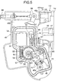
- Fig.5 is an enlarged view of essential portions of Fig.
- Fig. 6 is an enlarged view of essential portions of Fig. 2 when the door-locking device has been brought into a locking state
- Fig.7 is an exploded perspective view of a universal joint
- Fig.8 is a perspective view showing a state in which an inner cable has been connected to the universal joint
- Fig.9 is a perspective view of a retaining case.
- Figs. 1 to 9 show an embodiment of the present invention.
- a cylinder body 12 of a cylinder lock 11 and a casing 14 of a door-locking device 13 for switching over between a door-locking state and a door-unlocking state in response to the key operation of the cylinder lock 11 are mounted to, for example, a right door D in an automobile vehicle, so that a turning force generated with the key operation of the cylinder lock 11 is transmitted to the door-locking device 13 through a turning movement-transmitting member 15 having a flexibility.
- a handle case 16 is mounted to an outer side of the door D, and an outside handle 17 is vertically turnably mounted to the handle case 16.
- the cylinder body 12 of the cylinder lock 11 is inserted from the inside into a support tube 18 integrally provided on the handle case 16 to extend inwards of the door D, and a retaining ring 19 engaged with both of the support tube 18 and the cylinder body 12 is mounted to the support tube 18, whereby the cylinder body 12 is mounted to the door D.
- a rotor 21 having a key hole 20 is turnably inserted into the cylinder body 12, and a plurality of tumblers 23 disengaged from the cylinder body 12 by inserting a normal key 22 into the key hole 20 are disposed at a plurality of points spaced apart from one another in an axial direction of the rotor 21.
- a return spring 24 for returning the rotor 21 to a neutral position is mounted between the rotor 21 and the cylinder body 12.
- a connecting shaft portion 21a is provided coaxially and integrally at a rear end of the rotor 21, and one end of the turning movement-transmitting member 15 is operatively connected to the connecting shaft portion 21a.
- the turning movement-transmitting member 15 comprises an inner cable 27 inserted through an outer cable 26 which is engaged with and retained at one end thereof on a case 25 detachably connected to the cylinder body 12.
- One end of the inner cable 27 protruding from one end of the outer cable 26 is operatively connected to the connecting shaft portion 21a of the rotor 21 through a power-transmitting mechanism 28 accommodated in the case 25.
- the case 25 comprises a first case half 29 fastened to the cylinder body 12, and a second case half 30 engaged with the first case half 29.
- the first case half 29 is fastened by a screw member 31 to an upper support plate portion 12a integrally provided at a rear end of the cylinder body 12 to extend upwards, and a pair of engagement claws 33 provided on the second case half 30 are resiliently engaged into a pair of engagement bores 32 provided in the first case half 29 on opposite sides of the cylinder lock 11, respectively.
- the second case half 30 is sandwiched between the first case half 29 and the upper support plate portion 12a.
- a lower support plate portion 12b is integrally provided at the rear end of the cylinder body 12 to extend downwards, and a positioning tube 35 is provided integrally and projectingly on the second case half 30 to determine the position of the case 25 relative to the cylinder body 12 by fitting a bottomed cylindrical positioning pin 34 projectingly provided on the lower support plate portion 12b into the positioning tube 35.
- An engagement tube member 36 is secured to one end of the outer cable 26, so that the one end of the outer cable 26 is positioned and retained on the case 25 by bringing engagement projections 38, 38 provided integrally on lower portions of the case halves 29 and 30 into engagement in an annular groove 37 provided in an outer periphery of the engagement tube member 36.
- the inner cable 27 is mounted to extend through the engagement tube member 36 into the case 25, and the power-transmitting mechanism 28 is comprised of a first bevel gear 39 as a transmitting wheel relatively non-turnably connected to the rotor 21 in response to the mounting of the case 25 to the cylinder body 12, and a second bevel gear 40 which is meshed with the first bevel gear 39 and has an axis perpendicular to the first bevel gear 39, and to which one end of the inner cable 27 is secured coaxially.
- a first bevel gear 39 as a transmitting wheel relatively non-turnably connected to the rotor 21 in response to the mounting of the case 25 to the cylinder body 12, and a second bevel gear 40 which is meshed with the first bevel gear 39 and has an axis perpendicular to the first bevel gear 39, and to which one end of the inner cable 27 is secured coaxially.
- the first bevel gear 39 is turnably carried between the first and second case halves 29 and 30 and has coaxially a connecting tube portion 39a facing into an opening 41 provided in the second case half 30, and the connecting shaft portion 21a of the rotor 21 is relatively non-turnably fitted into a fitting recess 42 provided coaxially in the connecting tube portion 39a.
- the second bevel gear 40 is also turnably carried between both of the case halves 29 and 30 in such a manner that it is maintained meshed with the first bevel gear 39.
- the first bevel gear 39 of the power-transmitting mechanism 28 is relatively non-turnably connected to the connecting shaft portion 21a of the rotor 21 carried on the cylinder body 12 by mounting the case 25 to the cylinder body 12 mounted to the door D.
- the power-transmitting mechanism 28 converts the turning movement of the first bevel gear 39 responsive to the turning of the rotor 21 of the cylinder lock 11 by the key operation into the twisting motion of the inner cable 27 of the turning movement-transmitting member 15.
- the turning motion of the rotor 21 is transmitted to one end of the turning movement-transmitting member 15 through the power-transmitting mechanism 28 comprising the first and second bevel gears 39 and 40 having axes intersecting each other at right angles. Therefore, the turning movement-transmitting member 15 is operatively connected at one end to the rotor 21 to extend in a direction perpendicular to the axis of the rotor 21.
- the twisting motion of the turning movement-transmitting member 15 is converted into the turning movement of a turn member 45 as an input member of the door-locking device 13, but if the turning movement-transmitting member 15 is longer, a loss of transmission of a turning force provided by the twisting of the turning movement-transmitting member 15 is larger. Therefore, the power-transmitting mechanism 28 is constructed to transmit the turning movement of the rotor 21 at a double angle to the inner cable 27 by the meshing of the first and second bevel gears 39 and 40 with each other.
- the turn member 45 when it is required to turn the turn member 45, for example, through 30 degree in response to the switching of the unlocking state and the locking state of the door-locking device 13 from one to another, the turn member 45 can be turned reliably in a range of 30 degree or more by the transmission of the turning force provided by the twisting motion of the turning movement-transmitting member 15.
- the casing 14 of the door-locking device 13 is provided with an admission groove 46 into which a striker (not shown) on a vehicle body can be admitted.
- the door D is locked in a closed state by inhibiting the turning of a latch 47 which is turnably carried on the casing 14 in such a manner that it is brought into engagement with the striker admitted in the admission groove 46 and rotated upon closing of the door D.
- the locked state of the door D is canceled by permitting the turning of the latch 47, whereby the door D is brought into the unlocked state. In this unlocked state, the door D can be opened.
- the casing 14 is covered with a cover 48 made of a synthetic resin.
- the cover 48 is formed into a substantially L-shape and integrally provided with a main cover portion 48a formed into a box-shape with a side closer to the casing 14 being opened, and a support wall 48b rising from the main cover portion 48a.
- a door-locking lever shaft 49 having an axis parallel to a direction of extension of the admission groove 46 in the casing 14 is turnably carried on the support wall 48b, and a door-locking lever 50 is fixed to the door-locking lever shaft 49.
- the locking state and the unlocking state of the door-locking device 13 are switched over from one to another by the turning of the door-locking lever 50, i.e., the door-locking lever shaft 49 between a locking position and an unlocking position.
- a protrusion 51 extending in an endless shape is integrally provided on the support wall 48b of the cover 48 on the side of a striker-admission port of the admission groove 46.
- a lid plate 52 made of a synthetic resin is mounted to the protrusion 51, and an operating chamber 53 is defined between the support wall 48b of the cover 48 and the lid plate 52, so that one end of the door-locking lever shaft 49 faces into the operating chamber 53.
- an electric motor 54 having a rotational axis parallel to a plane perpendicular to an axis of the door-locking lever shaft 49; a worm 55 connected coaxially to an output shaft of the electric motor 54; a worm wheel 56 meshed with the worm 55 and having an axis parallel to the door-locking lever shaft 49; a pinion 57 connected coaxially to the worm wheel 56 for turning movement in a limited range relative to the worm wheel 56; a sector gear 58 connected coaxially for relative non-turning movement to the door-locking lever shaft 49 and meshed with the pinion 57; a slide plate 59 connected at one end to the sector gear 58; a key-operation input lever 45 having an axis parallel to the door-locking lever shaft 49; and an arm 60 integrally provided on the sector gear 58, so that it can be brought into engagement with the key-operation input lever 45.
- the electric motor 54 is rotatable in normal and reverse directions and clamped between the support wall 48b of the cover 48 and the lid plate 52 in such a manner that it is partially accommodated in a recess 61 provided in the support wall 48b of the cover 48.
- the worm wheel 56 and the pinion 57 are turnably carried on a support shaft 62 supported between the support wall 48b and the lid plate 52.
- a spring (not shown) is mounted between the worm wheel 56 and the support wall 48b and acts to return the worm wheel 56 to a position before being turned in the normal and reverse directions, when the electric motor 54 is at stoppage of operation.
- a shaft portion 58a integrally provided on the sector gear 58 is passed air-tightly and turnably through the lid plate 52 to protrude to the outside, and the other end of the shaft portion 58a is relatively non-turnably fitted into one end of the door-locking lever shaft 49.
- a positioning projection 63 is provided on the sector gear 58 to protrude toward the pinion 57, and a positioning recess 64 is provided in the pinion 57, so that the positioning projection 63 can be fitted into the positioning recess 64.
- the slide plate 59 is formed of a synthetic resin to extend along a plane perpendicular to an axis of turning of the sector gear 58 and placed in sliding contact with the support wall 48b. Moreover, an elongated bore 65 is provided in the slide plate 59 to extend along a lengthwise direction of the slide plate 59, and a pin 66 embedded in the support wall 48b is inserted through the elongated bore 65, whereby the slide plate 59 is guided so that it is moved in the lengthwise direction.
- a pair of movable contacts 67, 67 electrically connected to each other are fixed to the slide plate 59, so that the locking positions and the unlocking positions of the door-locking lever shaft 49 and the door-locking lever 50 are detected by switching over the electric connection and disconnection of the movable contacts 67 to and from a plurality of stationary contacts (not shown) fixed to the lid plate 52 by the sliding operation of the slide plate 59, i.e., the turning movements of the sector gear 58, the door-locking lever shaft 49 and the door-locking lever 50.
- a knob lever 68 is fixed to one end of the shaft portion 58a integrally provided on the sector gear 58 outside the lid plate 52 .
- the knob lever 68 is turned in response to the operation of a locking knob (not shown) mounted on an inner surface of the door D. Namely, the locking state and the unlocking state of the door-locking device 13 are switched over from one to another even by the operation of the locking knob.
- the key-operation input lever 45 is formed into a fan-shape.
- a shaft portion 45a integrally provided on the key-operation input lever 45 at a location corresponding to an essential portion of the fan-shape is turnably supported at one end on a support shaft 52a integrally provided on the lid plate 52, and also turnably supported at the other end on a support tube portion 71 integrally provided on the support wall 48b to extend air-tightly through the support tube portion 71.
- a pair of engagement projections 72 and 73 are integrally provided on the key-operation input lever 45 and spaced apart from each other in a circumferential direction of the key-operation input lever 45, and an engagement pin 74 capable of being brought into engagement with the engagement projections 72 and 73 are projectingly provided at a tip end of an arm 60 extending from the sector gear 58 toward the key-operation input lever 45.
- a turning force is input from the other end of the turning movement-transmit ting member 15 to the key-operation input lever 45.
- the key-operation input lever 45 is turned in a counterclockwise direction in Fig.2, whereby one of the engagement projections 72 is brought into engagement with the engagement pin 74, thereby permitting the arm 60, i.e., the sector gear 58 and the door-locking lever shaft 49 to be turned in a clockwise direction in Fig. 2.
- the rotor 21 of the cylinder lock 11 is returned to the neutral position in response to the releasing of the operating force for bringing the cylinder lock 11 to the unlocking position, and the key-operation input lever 45 is also returned to the neutral position, as shown in Fig. 5.
- the arm 60 is left behind, and the door-locking lever shaft 49 remains in the unlocking position.
- the key-operation input lever 45 When the cylinder lock 11 is then operated by the key to the locking position, the key-operation input lever 45 is turned in a clockwise direction in Fig. 6 from the neutral position shown in Fig. 5, whereby the other engagement projection 73 is brought into engagement with the engagement pin 74, thereby permitting the arm 60, i.e. , the sector gear 58 and the door-locking lever shaft 49 to be turned in a counterclockwise direction in Fig. 6. Even at this time, the rotor 21 of the cylinder lock 11 is returned to the neutral position in response to the releasing of the operating force for bringing the cylinder lock 11 to the locking position. The key-operation input lever 45 is also returned to the neutral position, as shown in Fig. 5, and the door-locking lever shaft 49 remains in the locking position.
- a pair of movable contacts 75, 75 electrically connected to each other are fixed to the key-operation input lever 45, and it is detected by the electrical connection and disconnection of the movable contacts 75 to and from the stationary contacts fixed to the lid plate 52 that the key-operation input lever 45 has been turned to the locking position and the unlocking position, i.e., that the locking and unlocking operations of the cylinder lock 11 have been carried out.
- the turning movement-transmitting member 15 is connected at one end to the shaft portion 45a of the key-operation input lever 45 through a universal joint 76.
- the universal joint 76 is comprised of a first joint element 77 integrally formed at an end of the shaft portion 45 protruding from the support tube portion 71, and a second joint element 78 coupled to the other end of the inner cable 27 of the turning movement-transmitting member 15.
- the first joint element 77 comprises a first support shaft portion 80 disposed coaxially with the shaft portion 45a and having a semispherical fitting recess 79 at a tip end, and a plurality of, for example, four engagement arms 81 extending radially from the first support shaft portion 80.
- the second joint element 78 integrally includes a second support shaft portion 82 which is oscillatably fitted at its tip end into the fitting recess 79, an engagement tube portion 83 which surrounds the second support shaft portion 82 coaxially and has notches 84 at a plurality of, for example, four points equally spaced apart from one another in a circumferential direction, so that the engagement arm portions 81 are engaged into the notches 84, and a connecting tube portion 85 extending in a direction opposite from the first joint element 77 coaxially with the second support shaft portion 82 and the engagement tube portion 83.
- the connecting tube portion 85 is provided with a bottomed insertion bore 86 rectangular in cross section, and also provided with an opening 87 into which an intermediate portion of the insertion bore 86 faces, and an engagement claw 88 disposed in the opening 87 in such a manner that its base end is connected to an end edge of the opening 87 closer to an open end of the insertion bore 86.
- a connecting member 90 is secured to the other end of the inner cable 27 of the turning movement-transmitting member 15.
- the connecting member 90 is capable of being inserted into the insertion bore 86, and has an engagement bore 89 into which the engagement claw 88 can be resiliently engaged.
- the other end of the inner cable 27 is fixedly connected to the second joint element 78 through the connecting member 90 by inserting the connecting member 90 into the insertion bore 86 to bring the engagement projection 88 into resilient engagement in the engagement bore 89.
- the universal joint 76 is accommodated in a retaining case 91 which is fastened to an outer surface of the support wall 48b of the cover 48, and an angle formed by the other end of the turning movement-transmitting member 15 with respect to the axis if the key-operating input lever 45 is determined by the retaining case 91.
- the retaining case 91 comprises a pair of case halves 92 and 93.
- Fastening plate portions 92a, 92a are provided one by one at circumferentially opposite ends of one case half 92
- fastening plate portions 93a are provided one by one at circumferentially opposite ends of the other case half 93 and inserted between the fastening plate portions 92a, 92a.
- the retaining case 91 is fastened to the outer surface of the support wall 48b by allowing a screw member 94 inserted through the fastening plate portions 92a, 92a, 93a, 93a to be threadedly meshed with a boss 95 projectingly provided on the outer surface of the support wall 48b.
- a positioning pin 96 is provided integrally and projectingly on the outer surface of the support wall 48b for determining a direction of inclination of the retaining case 91 with respect to the axis of the key-operating input lever 45 by fitting the positioning pin 96 into the retaining case 91.
- the other end of the outer cable 26 of the turning movement-transmitting member 15 is inserted into a tip end of the retaining case 91.
- the other end of the turning movement-transmitting member 15 is operatively connected to the key-operation input lever 45 of the door-locking device 13, but the door-locking device 13 and the turning movement-transmitting member 15 are constructed in the form of a unit by fastening the retaining case 91 with the universal joint 76 accommodated therein to the support wall 48b of the cover 48 in the door-locking device 13.
- An opening lever 97 is carried on the casing 14 of the door-locking device 13, so that it is turned in response to the inputting of a door-opening force.
- a lengthwise one end of the opening lever 97 protrudes from the casing 14, and an operating force corresponding to the operation of the outside handle 17 mounted on the outer surface of the door D is input to such one end.
- An input lever 98 is turnably carried on the cover 48 of the door-locking device 13 and turned by the pulling of the cable 99 responsive to the operation of an inside handle (not shown) mounted on the inner surface of the door D, and a power in a door-opening direction is transmitted from input lever 98 to the opening lever 96.
- the turning movement-transmitting member 15 having the flexibility is disposed between the cylinder lock 11 and the door-locking device 13 in such a manner that the turning force of the rotor 21 is transmitted to the door-locking lever shaft 49 in the door-locking device 13 by the twisting motion responsive to the turning movement of the rotor 21 in the cylinder lock 11. Therefore, it is not necessary to dispose the axis of rotation of the rotor 21 and the axis of the door-locking lever shaft 49 on the same axis and thus, the degree of freedom for the relative disposition of the cylinder lock 11 and the door-locking device 13 can be increased.
- the power-transmitting mechanism 28 including the first bevel gear 39 relatively non-turnably connected to the rotor 21 in response to the mounting of the case to the cylinder body 12 is accommodated in the case 25 detachably connected to the cylinder body 12 of the cylinder lock 11, and is connected to the one end of the turning movement-transmitting member 15 in such a manner that the turning movement of the first bevel gear 39 is converted into the twisting motion of the turning movement-transmitting member 15.
- the turning movement-transmitting member 15 is operatively connected at the other end thereof to the door-locking lever shaft 49 of the door-locking device 13 in such a manner that the door-locking device 13 and the turning movement-transmitting member 15 are constructed in the form of the unit.
- one end of the rotor 21 of the cylinder lock 11 and one end of the turning movement-transmitting member 15 are operatively connected to each other by mounting the door-locking device 13 constructed as the unit along with the turning movement-transmitting member 15 to the door D and then mounting the case 25 to the cylinder body 12 of the cylinder lock 11 mounted to the door D. Therefore, the operation for connecting the cylinder lock 11 and the door-locking device 13 by the turning movement-transmitting member 15 is facilitated.
- the turning movement-transmitting member 15 is operatively connected at one end to the rotor 21 of the cylinder lock 11 to extend in the direction perpendicular to the axis of the rotor 21, an area where the one end of the turning movement-transmitting member 15 is connected to the rotor 21 of the cylinder lock 11 cannot occupy a large space at the rear of the cylinder lock 11, and it is unnecessary to take into consideration the interference with a glass or the like accommodated in the door D.
- the power-transmitting mechanism 28 mounted between the rotor 21 of the cylinder lock 11 and the one end of the turning movement-transmitting member 15 comprises the first and second bevel gears 39 and 40 meshed with each other, the loss of transmission of the turning force by the twisting of the turning movement-transmitting member 15 can be absorbed by adjusting the number of teeth of the bevel gears 39 and 40 to increase the transmission ratio.
- the turning movement-transmitting member 15 comprising the inner cable 27 inserted through the outer cable 26 is used in the above-described embodiment, but any other turning movement-transmitting member 15 may be used, if it transmits a turning force by a twisting motion responsive to the turning of the rotor 21 in the cylinder lock 11, and for example, a chain or the like may be used.
- the power-transmitting mechanism 28 is comprised of the first and second bevel gears 39 and 40 meshed with each other in the above-described embodiment, but a power-transmitting mechanism 28 is not limited to one comprising the first and second bevel gears 39 and 40, if a turning movement-transmitting member can be extended in the direction perpendicular to the rotational axis of the rotor 21.
- the above-described embodiment is of the arrangement in which the turning force is transmitted from the turning movement-transmitting member 15 to the intermediate of the path for transmitting the power from the electric motor 54 to the locking lever shaft 49, but may be of an arrangement in which a turning force is transmitted from a turning movement-transmitting means directly to the door-locking lever shaft 49.
Landscapes
- Lock And Its Accessories (AREA)
Applications Claiming Priority (3)
| Application Number | Priority Date | Filing Date | Title |
|---|---|---|---|
| JP2002365795 | 2002-12-17 | ||
| JP2002365795A JP3914149B2 (ja) | 2002-12-17 | 2002-12-17 | 車両のドア開閉装置 |
| PCT/JP2003/014542 WO2004055304A1 (fr) | 2002-12-17 | 2003-11-14 | Dispositif d'ouverture/fermeture de portiere de vehicule |
Publications (3)
| Publication Number | Publication Date |
|---|---|
| EP1577471A1 true EP1577471A1 (fr) | 2005-09-21 |
| EP1577471A4 EP1577471A4 (fr) | 2010-08-25 |
| EP1577471B1 EP1577471B1 (fr) | 2014-07-16 |
Family
ID=32588281
Family Applications (1)
| Application Number | Title | Priority Date | Filing Date |
|---|---|---|---|
| EP20030772790 Expired - Lifetime EP1577471B1 (fr) | 2002-12-17 | 2003-11-14 | Dispositif d'ouverture/fermeture de portière de véhicule |
Country Status (7)
| Country | Link |
|---|---|
| US (1) | US7703310B2 (fr) |
| EP (1) | EP1577471B1 (fr) |
| JP (1) | JP3914149B2 (fr) |
| CN (1) | CN100537990C (fr) |
| AU (1) | AU2003280808A1 (fr) |
| BR (1) | BR0317369B1 (fr) |
| WO (1) | WO2004055304A1 (fr) |
Cited By (1)
| Publication number | Priority date | Publication date | Assignee | Title |
|---|---|---|---|---|
| EP2458118A4 (fr) * | 2009-07-24 | 2012-12-12 | Aisin Seiki | Dispositif de serrure de porte pour véhicule |
Families Citing this family (31)
| Publication number | Priority date | Publication date | Assignee | Title |
|---|---|---|---|---|
| GB2412692B (en) | 2004-03-30 | 2006-08-09 | Mitsui Mining & Smelting Co | Door lock system |
| JP4504837B2 (ja) * | 2005-02-28 | 2010-07-14 | 三井金属鉱業株式会社 | ドアロック装置 |
| JP2007223410A (ja) * | 2006-02-22 | 2007-09-06 | Honda Motor Co Ltd | 車両のドア構造及びドアロック装置の取り付け方法 |
| FR2899619B1 (fr) * | 2006-04-11 | 2012-09-21 | Valeo Securite Habitacle | Agencement de transmission de mouvement entre notamment un verrou et une serrure de porte de vehicule |
| JP4673797B2 (ja) * | 2006-05-30 | 2011-04-20 | 株式会社ホンダロック | 車両用ドアロック装置 |
| JP2009228306A (ja) * | 2008-03-24 | 2009-10-08 | Aisin Kiko Co Ltd | 電動式ドアラッチ装置 |
| JP5393570B2 (ja) * | 2010-03-31 | 2014-01-22 | アイシン機工株式会社 | 車両用リッドロック装置 |
| DE202010011541U1 (de) * | 2010-08-18 | 2011-11-23 | BROSE SCHLIEßSYSTEME GMBH & CO. KG | Antriebsanordnung |
| JP5352654B2 (ja) * | 2011-03-30 | 2013-11-27 | アイシン精機株式会社 | 車両用ドアロック装置 |
| US9284758B2 (en) * | 2012-06-28 | 2016-03-15 | Mitsui Kinzoku Act Corporation | Operating device for a vehicle door latch |
| DE102013009112A1 (de) * | 2013-05-29 | 2014-12-04 | Huf Hülsbeck & Fürst Gmbh & Co. Kg | Moduleinheit zum Öffnen- und Schließen von Flügeln |
| CN103643844B (zh) * | 2013-12-16 | 2016-04-06 | 三一汽车制造有限公司 | 工程机械、驾驶室及车门内部闩锁结构 |
| JP6364650B2 (ja) * | 2014-08-05 | 2018-08-01 | 三井金属アクト株式会社 | ドアラッチ用アクチュエータ |
| KR101610499B1 (ko) * | 2014-08-28 | 2016-04-07 | 현대자동차주식회사 | 차량용 도어 래치 장치 |
| JP6368954B2 (ja) * | 2014-09-08 | 2018-08-08 | 三井金属アクト株式会社 | 車両用ドアラッチ装置 |
| DE102014114512A1 (de) * | 2014-10-07 | 2016-04-07 | Kiekert Aktiengesellschaft | Kraftfahrzeugtürverschluss |
| KR101786988B1 (ko) * | 2016-01-27 | 2017-10-17 | 주식회사 라맥스 | 도어락 케이싱 유닛 |
| DE102016111837A1 (de) * | 2016-06-28 | 2017-12-28 | Kiekert Ag | Kraftfahrzeugschloss |
| CN107620529B (zh) | 2016-07-15 | 2020-12-15 | 株式会社安成 | 车辆用门锁装置 |
| JP6627672B2 (ja) | 2016-07-20 | 2020-01-08 | 株式会社アンセイ | 車両用ドアロック装置 |
| JP6703271B2 (ja) * | 2016-09-21 | 2020-06-03 | 株式会社アンセイ | 車両用ドアロック装置 |
| JP6627729B2 (ja) | 2016-11-25 | 2020-01-08 | 株式会社アンセイ | 車両用ドアロック装置 |
| CN106677635B (zh) * | 2016-12-22 | 2019-02-12 | 华侨大学 | 一种汽车门把手装置 |
| ES2928686T3 (es) * | 2017-05-16 | 2022-11-21 | U Shin Italia Spa | Dispositivo de desenclavamiento de una cerradura de puerta |
| CN110454009A (zh) * | 2018-05-08 | 2019-11-15 | 麦格纳覆盖件有限公司 | 具有线缆接合部的车辆闩锁衬套 |
| JP6627920B2 (ja) | 2018-06-26 | 2020-01-08 | 株式会社アンセイ | 車両用ドアロック装置 |
| CN111278251B (zh) * | 2020-02-17 | 2021-05-14 | 北京小马慧行科技有限公司 | 锁定机构、车载显示器及运载工具 |
| DE102021101741A1 (de) * | 2021-01-27 | 2022-07-28 | Bayerische Motoren Werke Aktiengesellschaft | Türaußengriffsystem für einen Personenkraftwagen sowie hiermit ausgestatteter Personenkraftwagen |
| JP7827980B2 (ja) | 2022-06-06 | 2026-03-11 | 株式会社アンセイ | 車両用開閉体のロック装置 |
| CN118167150A (zh) * | 2024-04-07 | 2024-06-11 | 贵州华昌汽车电器有限公司 | 一种防盗车门锁芯 |
| DE102024122607A1 (de) * | 2024-08-08 | 2026-02-12 | Kiekert Aktiengesellschaft | Kraftfahrzeug-Schloss |
Family Cites Families (28)
| Publication number | Priority date | Publication date | Assignee | Title |
|---|---|---|---|---|
| US1368526A (en) * | 1918-03-25 | 1921-02-15 | Benjamin G Patterson | Combination-lock |
| US1724424A (en) * | 1927-10-11 | 1929-08-13 | Jr John Sandholdt | Lock for multiple doors |
| US1880135A (en) * | 1930-03-10 | 1932-09-27 | Charles W Heath | Automatic locking gas tank cover |
| US1857654A (en) * | 1930-11-10 | 1932-05-10 | Wesley J Mylar | Lock for containers |
| US1918093A (en) * | 1932-09-07 | 1933-07-11 | Harry W Gang | Gasoline tank and ignition locking device |
| US2427436A (en) * | 1945-06-18 | 1947-09-16 | Ford Motor Co | Door handle and latch construction |
| US4609233A (en) * | 1983-11-03 | 1986-09-02 | Timberline Supply, Ltd. | Furniture locking system |
| JPS6119789A (ja) | 1984-12-25 | 1986-01-28 | Chlorine Eng Corp Ltd | 複極電極 |
| DE3902776A1 (de) * | 1988-08-13 | 1990-02-15 | Kiekert Gmbh Co Kg | Kraftfahrzeugtuerverschluss mit zentralverriegelungsantrieb und diebstahlsicherung |
| US5233849A (en) * | 1992-09-14 | 1993-08-10 | General Motors Corporation | Remote key actuator for vehicle trunk lock |
| JP3371485B2 (ja) | 1993-09-29 | 2003-01-27 | アイシン精機株式会社 | 車両用ドアロツク装置 |
| JP3295524B2 (ja) | 1994-03-31 | 2002-06-24 | 株式会社大井製作所 | 作動力伝達装置 |
| US5537848A (en) * | 1994-06-27 | 1996-07-23 | General Motors Corporation | Deadbolt locking system |
| GB9413388D0 (en) * | 1994-07-02 | 1994-08-24 | Rover Group | A vehicle locking system |
| US5715713A (en) * | 1996-01-11 | 1998-02-10 | General Motors Corporation | Door latch locking actuator assembly |
| US6032496A (en) * | 1997-07-18 | 2000-03-07 | Robert Bosch Gmbh | Door lock arrangement for motor vehicles |
| US5894749A (en) * | 1997-09-03 | 1999-04-20 | Atoma International Corp. | Latching system with flexible release |
| US5996382A (en) * | 1998-03-10 | 1999-12-07 | Ford Global Technologies, Inc. | Automotive lock mechanism using a torque cable drive |
| DE19823188C2 (de) * | 1998-05-23 | 2001-03-01 | Kiekert Ag | Kraftfahrzeugtürverschluß |
| DE29822913U1 (de) * | 1998-12-23 | 2000-07-13 | Witte-Velbert GmbH & Co. KG, 42551 Velbert | Anordnung zur Übertragung der Drehbetätigung zwischen Schließzylinder und Verschluß eines Kraftfahrzeuges |
| DE19912321C1 (de) * | 1999-03-19 | 2000-12-14 | Huf Huelsbeck & Fuerst Gmbh | Verschlussvorrichtung, insbesondere für Schließfunktionen am Heck eines Fahrzeugs |
| GB9920059D0 (en) * | 1999-08-24 | 1999-10-27 | Meritor Light Vehicle Sys Ltd | Key barrel drive arrangement |
| JP2002129807A (ja) * | 2000-10-26 | 2002-05-09 | Oi Seisakusho Co Ltd | 車両用ドアロック装置 |
| JP3777968B2 (ja) * | 2000-10-26 | 2006-05-24 | アイシン精機株式会社 | ドアロック装置 |
| DE20109250U1 (de) | 2001-06-01 | 2001-10-18 | Huf Hülsbeck & Fürst GmbH & Co. KG, 42551 Velbert | Schließanlage |
| DE10126909A1 (de) * | 2001-06-01 | 2002-12-12 | Huf Huelsbeck & Fuerst Gmbh | Schließvorrichtung |
| JP4015638B2 (ja) * | 2004-05-10 | 2007-11-28 | 株式会社ホンダロック | 車両のドア開閉装置 |
| US7302818B2 (en) * | 2004-05-10 | 2007-12-04 | Kabushiki Kaisha Honda Lock | Apparatus for locking and unlocking vehicle door |
-
2002
- 2002-12-17 JP JP2002365795A patent/JP3914149B2/ja not_active Expired - Fee Related
-
2003
- 2003-11-14 BR BR0317369A patent/BR0317369B1/pt not_active IP Right Cessation
- 2003-11-14 EP EP20030772790 patent/EP1577471B1/fr not_active Expired - Lifetime
- 2003-11-14 WO PCT/JP2003/014542 patent/WO2004055304A1/fr not_active Ceased
- 2003-11-14 CN CNB200380106723XA patent/CN100537990C/zh not_active Expired - Fee Related
- 2003-11-14 AU AU2003280808A patent/AU2003280808A1/en not_active Abandoned
- 2003-11-14 US US10/535,995 patent/US7703310B2/en not_active Expired - Fee Related
Cited By (2)
| Publication number | Priority date | Publication date | Assignee | Title |
|---|---|---|---|---|
| EP2458118A4 (fr) * | 2009-07-24 | 2012-12-12 | Aisin Seiki | Dispositif de serrure de porte pour véhicule |
| US8438888B2 (en) | 2009-07-24 | 2013-05-14 | Aisin Seiki Kabushiki Kaisha | Door lock device for vehicle |
Also Published As
| Publication number | Publication date |
|---|---|
| BR0317369A (pt) | 2005-11-16 |
| JP2004197377A (ja) | 2004-07-15 |
| US20060214467A1 (en) | 2006-09-28 |
| EP1577471B1 (fr) | 2014-07-16 |
| AU2003280808A1 (en) | 2004-07-09 |
| CN100537990C (zh) | 2009-09-09 |
| US7703310B2 (en) | 2010-04-27 |
| WO2004055304A1 (fr) | 2004-07-01 |
| JP3914149B2 (ja) | 2007-05-16 |
| CN1729341A (zh) | 2006-02-01 |
| AU2003280808A8 (en) | 2004-07-09 |
| EP1577471A4 (fr) | 2010-08-25 |
| BR0317369B1 (pt) | 2013-10-08 |
Similar Documents
| Publication | Publication Date | Title |
|---|---|---|
| US7703310B2 (en) | Door opening and closing device for vehicle and assembly method thereof | |
| JP4418319B2 (ja) | 自動車用ドアラッチ装置 | |
| US8870247B2 (en) | Door locking apparatus | |
| CN102149889B (zh) | 车门开闭装置 | |
| EP0926307B1 (fr) | Serrure de porte pour véhicule | |
| US7213428B2 (en) | Apparatus for locking and unlocking vehicle door | |
| US20040262927A1 (en) | Door lock device | |
| KR960011528B1 (ko) | 차량 전기 도어 로크 작동기 | |
| AU2005307310B2 (en) | Door lock apparatus for vehicles | |
| WO2014203930A1 (fr) | Poignée de porte de véhicule | |
| US5582448A (en) | Switch mechanism for a vehicle door locking device | |
| US7302818B2 (en) | Apparatus for locking and unlocking vehicle door | |
| US7063360B2 (en) | Door lock device | |
| EP1884610A2 (fr) | Dispositif d'ouverture et de fermeture de portière d'un véhicule | |
| CN112727269B (zh) | 门闩装置 | |
| US20230366247A1 (en) | Vehicle door lock apparatus | |
| JP2002283964A (ja) | 車両のステアリングロック装置 | |
| JP4145680B2 (ja) | 車両のドア開閉装置 | |
| US5636879A (en) | Coupling structure between door lock and door lock-actuator | |
| JP4327677B2 (ja) | 自動車用ドアラッチ装置 | |
| CN112727268A (zh) | 门闩装置 | |
| EP4621172A1 (fr) | Dispositif de barillet de serrure pour portière de véhicule | |
| JP2025145012A (ja) | 車両ドアのキーシリンダ装置 | |
| JP3311293B2 (ja) | 車両用ドアロック装置 | |
| JP2005282223A (ja) | ドアロック装置 |
Legal Events
| Date | Code | Title | Description |
|---|---|---|---|
| PUAI | Public reference made under article 153(3) epc to a published international application that has entered the european phase |
Free format text: ORIGINAL CODE: 0009012 |
|
| 17P | Request for examination filed |
Effective date: 20050525 |
|
| AK | Designated contracting states |
Kind code of ref document: A1 Designated state(s): AT BE BG CH CY CZ DE DK EE ES FI FR GB GR HU IE IT LI LU MC NL PT RO SE SI SK TR |
|
| AX | Request for extension of the european patent |
Extension state: AL LT LV MK |
|
| DAX | Request for extension of the european patent (deleted) | ||
| RBV | Designated contracting states (corrected) |
Designated state(s): DE FR GB |
|
| A4 | Supplementary search report drawn up and despatched |
Effective date: 20100728 |
|
| 17Q | First examination report despatched |
Effective date: 20110407 |
|
| REG | Reference to a national code |
Ref country code: DE Ref legal event code: R079 Ref document number: 60346493 Country of ref document: DE Free format text: PREVIOUS MAIN CLASS: E05B0065200000 Ipc: E05B0083360000 |
|
| GRAP | Despatch of communication of intention to grant a patent |
Free format text: ORIGINAL CODE: EPIDOSNIGR1 |
|
| RIC1 | Information provided on ipc code assigned before grant |
Ipc: E05B 65/20 20060101AFI20140110BHEP Ipc: E05B 17/04 20060101ALN20140110BHEP Ipc: B60J 5/00 20060101ALI20140110BHEP Ipc: E05B 53/00 20060101ALN20140110BHEP |
|
| INTG | Intention to grant announced |
Effective date: 20140203 |
|
| RIC1 | Information provided on ipc code assigned before grant |
Ipc: E05B 83/36 20140101AFI20140130BHEP Ipc: E05B 17/04 20060101ALN20140130BHEP Ipc: E05B 53/00 20060101ALN20140130BHEP Ipc: B60J 5/00 20060101ALI20140130BHEP |
|
| RIN1 | Information on inventor provided before grant (corrected) |
Inventor name: IJUIN, HIDETOSHI Inventor name: KATSUMATA, NAOKI Inventor name: KISHIKAWA, NOBUYUKI Inventor name: KOBAYASHI, FUMIO Inventor name: USUZAKI, YUUICHI |
|
| GRAS | Grant fee paid |
Free format text: ORIGINAL CODE: EPIDOSNIGR3 |
|
| GRAA | (expected) grant |
Free format text: ORIGINAL CODE: 0009210 |
|
| RAP1 | Party data changed (applicant data changed or rights of an application transferred) |
Owner name: HONDA MOTOR CO., LTD. Owner name: KABUSHIKI KAISHA HONDA LOCK |
|
| AK | Designated contracting states |
Kind code of ref document: B1 Designated state(s): DE FR GB |
|
| REG | Reference to a national code |
Ref country code: GB Ref legal event code: FG4D |
|
| REG | Reference to a national code |
Ref country code: DE Ref legal event code: R096 Ref document number: 60346493 Country of ref document: DE Effective date: 20140828 |
|
| REG | Reference to a national code |
Ref country code: DE Ref legal event code: R097 Ref document number: 60346493 Country of ref document: DE |
|
| PLBE | No opposition filed within time limit |
Free format text: ORIGINAL CODE: 0009261 |
|
| STAA | Information on the status of an ep patent application or granted ep patent |
Free format text: STATUS: NO OPPOSITION FILED WITHIN TIME LIMIT |
|
| 26N | No opposition filed |
Effective date: 20150417 |
|
| REG | Reference to a national code |
Ref country code: FR Ref legal event code: PLFP Year of fee payment: 13 |
|
| PGFP | Annual fee paid to national office [announced via postgrant information from national office to epo] |
Ref country code: GB Payment date: 20151111 Year of fee payment: 13 Ref country code: DE Payment date: 20151110 Year of fee payment: 13 |
|
| PGFP | Annual fee paid to national office [announced via postgrant information from national office to epo] |
Ref country code: FR Payment date: 20151008 Year of fee payment: 13 |
|
| REG | Reference to a national code |
Ref country code: DE Ref legal event code: R119 Ref document number: 60346493 Country of ref document: DE |
|
| GBPC | Gb: european patent ceased through non-payment of renewal fee |
Effective date: 20161114 |
|
| REG | Reference to a national code |
Ref country code: FR Ref legal event code: ST Effective date: 20170731 |
|
| PG25 | Lapsed in a contracting state [announced via postgrant information from national office to epo] |
Ref country code: FR Free format text: LAPSE BECAUSE OF NON-PAYMENT OF DUE FEES Effective date: 20161130 |
|
| PG25 | Lapsed in a contracting state [announced via postgrant information from national office to epo] |
Ref country code: DE Free format text: LAPSE BECAUSE OF NON-PAYMENT OF DUE FEES Effective date: 20170601 Ref country code: GB Free format text: LAPSE BECAUSE OF NON-PAYMENT OF DUE FEES Effective date: 20161114 |