EP1577472B1 - Gleiterbauteil und Feststell- oder Austellvorrichtung für den Beschlag von Fensternflügeln - Google Patents
Gleiterbauteil und Feststell- oder Austellvorrichtung für den Beschlag von Fensternflügeln Download PDFInfo
- Publication number
- EP1577472B1 EP1577472B1 EP05102079A EP05102079A EP1577472B1 EP 1577472 B1 EP1577472 B1 EP 1577472B1 EP 05102079 A EP05102079 A EP 05102079A EP 05102079 A EP05102079 A EP 05102079A EP 1577472 B1 EP1577472 B1 EP 1577472B1
- Authority
- EP
- European Patent Office
- Prior art keywords
- locking device
- slide component
- notches
- section
- guide rail
- Prior art date
- Legal status (The legal status is an assumption and is not a legal conclusion. Google has not performed a legal analysis and makes no representation as to the accuracy of the status listed.)
- Expired - Lifetime
Links
Images

Classifications
-
- E—FIXED CONSTRUCTIONS
- E05—LOCKS; KEYS; WINDOW OR DOOR FITTINGS; SAFES
- E05C—BOLTS OR FASTENING DEVICES FOR WINGS, SPECIALLY FOR DOORS OR WINDOWS
- E05C17/00—Devices for holding wings open; Devices for limiting opening of wings or for holding wings open by a movable member extending between frame and wing; Braking devices, stops or buffers, combined therewith
- E05C17/02—Devices for holding wings open; Devices for limiting opening of wings or for holding wings open by a movable member extending between frame and wing; Braking devices, stops or buffers, combined therewith by mechanical means
- E05C17/04—Devices for holding wings open; Devices for limiting opening of wings or for holding wings open by a movable member extending between frame and wing; Braking devices, stops or buffers, combined therewith by mechanical means with a movable bar or equivalent member extending between frame and wing
- E05C17/12—Devices for holding wings open; Devices for limiting opening of wings or for holding wings open by a movable member extending between frame and wing; Braking devices, stops or buffers, combined therewith by mechanical means with a movable bar or equivalent member extending between frame and wing consisting of a single rod
- E05C17/24—Devices for holding wings open; Devices for limiting opening of wings or for holding wings open by a movable member extending between frame and wing; Braking devices, stops or buffers, combined therewith by mechanical means with a movable bar or equivalent member extending between frame and wing consisting of a single rod pivoted at one end, and with the other end running along a guide member
- E05C17/28—Devices for holding wings open; Devices for limiting opening of wings or for holding wings open by a movable member extending between frame and wing; Braking devices, stops or buffers, combined therewith by mechanical means with a movable bar or equivalent member extending between frame and wing consisting of a single rod pivoted at one end, and with the other end running along a guide member with braking, clamping or securing means at the connection to the guide member
-
- E—FIXED CONSTRUCTIONS
- E05—LOCKS; KEYS; WINDOW OR DOOR FITTINGS; SAFES
- E05B—LOCKS; ACCESSORIES THEREFOR; HANDCUFFS
- E05B15/00—Other details of locks; Parts for engagement by bolts of fastening devices
- E05B15/16—Use of special materials for parts of locks
- E05B15/1635—Use of special materials for parts of locks of plastics materials
Definitions
- the invention relates to a locking or Ausstellvortechnisch according to the introductory words of claim 1, in particular also a Gleiterbauteil for use in fitting technology.
- the locking device achieved in the installed state to set a (desired) opening angle of a wing of windows or doors. This is done with a, by a handle in at least two positions movable, concealed in a fitting groove of the casement arranged actuating linkage (in the installed state).
- the slider component has a fuselage section slidable in a guide rail, which can be attached between a rod section and two edge flanges of the guide rail and can be coupled to one end of a link. The other end of the link is hinged at a distance from a - defined by hinges of the wing - wing axis to a frame (rotatably arranged).
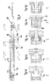
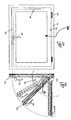
- the invention is concerned with the focus with an element of a complex device, which is not shown separately and extensively, only a schematic representation of such a locking or Ausstell adopted with a scissor arm and a C-shaped rail is in the FIGS. 1 . 5 and 6 shown. This is referred to insofar.
- the slider as a "slider member” is received in the preferred C-shaped rail as a guide rail and has certain properties due to its shapes.
- a bottom of the guide rail has in its longitudinal direction after a predetermined pitch arranged longitudinal window (graduation measure), which are spaced from each other by floor webs.
- the rod section has over the same pitch distributed over its length top depressions (depressions) whose lower side formations depending on the relative position of rod section relative to the ground engage in the bottom window or sit on the bottom webs.
- a clear height between the bottom webs and the underside of the edge flanges of the guide rail and a total height of the rod portion in the region of the formations and the height of shoulder surfaces on the body portion of the Gleiterbauteils are matched: When sliding the moldings on the floor webs sits the Gleiterbauteil with its shoulder surfaces on the Edge flanges of the guide rail firmly. An improved braking or detection results in this way.
- the slider component is elongated and consists of a large base section, in which two notches are inserted from above.
- the notches have an axially constant distance.
- a bridge forms, which extends in the height direction. This web is used to be used between two inner edges or such edges of the guide rail and guided, preferably in C-shaped rail.
- Mechanical braking forces are additionally and preferably applied in the notches, by engaging wedge-shaped protruding, in particular down, directed to the bottom of the base portion web portions of the C-shaped rail (claim 21) when the slider is pushed by the push rod upwards.
- the sliding member has a greater length than width and height. It is "elongated” trained. The width is narrow, compared to the long one.
- the notch shape does not necessarily have to be pointed at the bottom (claim 12), but a V-shaped notch shape is preferred in which a slight rounding occurs at the bottom and two walls are formed between which a respective web section engages from above from the C-rail ,
- the notches extend longitudinally (claim 3 or 14) but are together narrower than the width of the slider member.
- the V-shaped aligned walls are formed so that a wall is oriented substantially perpendicular and a more inclined relative to the vertical (claim 22).
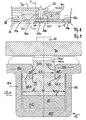
- FIG. 1 illustrates a non-braking position of the slider G, wherein a rising edge of a suppression 11 a immediately before a web 17 a, for further movement into the braking position after FIG. 1a ,
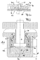
- the function of the slider is in the position of FIG. 1 , illustrated in the sectional view of FIG. 2 especially clear. It has a preferably made of plastic, as a plastically deformable material, formed body portion 40, in which - seen in section - two longitudinal notches 41,42 are introduced, which are provided with the inner distance b1. Each of these notches has a substantially vertically oriented wall 41.2 or 42.2 and a more inclined wall 41.1 or 42.1.
- the two vertical walls 41.2 and 42.2 delimit a web 40a, which rises and preferably protrudes from the top of the profile 15 through a through opening 15e (as a gap).
- the web 40a may centrally have a further opening 50 through which a pin 60 is inserted, to which a scissor arm 70 is rotatably articulated, wherein the pin 60 is formed on the upper side in the section 61 tapers.
- two horizontal web portions and two vertically, wedge-shaped and downwardly directed web portions 15a, 15a 'and 15b, 15b' are provided at the top.
- the latter vertically aligned portions engage in the notches 41,42 and guide the slider in its longitudinal movement.
- a rail portion 11 is placed below the slider G touching on its underside 40b and can exert forces on the slider by means of recesses and depressions controlled via its upper side, as shown in the following figures.
- the distance of the vertical walls 41.2 and 42.2 corresponds to b1, which distance is smaller than the total width b of the slider, which in turn is slightly narrower in its overall width than the space within the acting as a housing C-profile 15 with its side walls 15c, 15d.
- the length I of the slider is substantially greater than the width b, in particular more than four times as large.
- the height is determined by the upstanding web portion 40a, which is slightly smaller than the width and substantially lower than the length I. In the specific example, the height is only between 15% to 20% of the length.
- a substantially parallelepiped attachment 40a ' can be mounted substantially centrally, which is provided in the region of the bore 50 and is larger in area than this.
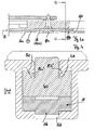
- the rail 11 lifts the slider G with its body 40, wherein the inclined wall 41.1 and 42.1 of the respective notch is applied directly to the projecting wedge-shaped web portion 15a 'and 15b' and the associated gap is reduced to zero.
- a gap is in the non-adjacent state in FIG. 4 illustrated, and with reference numerals S.1 and S.2 for the respective notch illustrated. In FIG. 2 this gap has become zero, in the braking position with the forces acting F 1 , F 2 , F 1 'and F 2 '.
- the surfaces 42.1 and 41.1 transmit normal forces to the center.
- F 0 of the slider By lifting F 0 of the slider, the force is increased and thus also the frictional forces or braking forces at the point of contact of the two surfaces or the respective surface pair of the respective notch.
- a saddle can be placed over the center bar and protrude into both columns, to convey the braking and holding forces.
- the walls of a respective notch ie the walls 41.1 and 41.2 on the one hand or the walls 42.1 and 42.2 have an angle between 20 ° and 40 °, essentially occupied by 30 °, between them.
- the downwardly projecting web 15a 'and 15b' is formed at such an angle.
- the C-profile 15 is pressed in the upper region to the center (on the vertical flanks 15c, 15d, which are used as a bending distance m) to the vertical surface portions 41.2 and 42.2 for abutment with the vertical wall portions of the downwardly projecting webs to be pressed, which limits the deformation of the C-rail. Due to the frictional engagement, the braking effect is present and the slider can absorb displacement forces in the longitudinal direction (and block movement).
- the rail 11 is provided with a number of elevations (recesses) 11 a, 11 ab and 11 b transverse to the longitudinal axis, which have a pitch.
- the pitch corresponds to the adjustment, wherein the pitch corresponds to openings 16a, 16b in the bottom 15f of the C-profile 15.
- the pitch T is dimensioned (graduation size) so that the standard thrusts of transmissions can be used and inaccuracies in the assembly can be compensated.
- the length of a breakthrough 16a simultaneously compensates for different transmission strokes, reference being made to the application which the FIGS.
- the adjustment can be defined at 180 ° rotary handle or at 90 ° rotary handle (actuation).
- the division of the rail 15 may correspond to the adjustment.
- a function of detection is described as follows.
- the rail 11 shifts. With a thickening or molding 11a, 11b, corresponding to the pitch T, it moves in its longitudinal movement against residual webs 17a, 17b, between the recesses 16a, 16b.
- the rail is raised and pushes the sliding member G with its body 40 upwards in the direction of the opening 15e of the C-profile.
- a plastic deformation of the slider which is preferably made of plastic, forms a tension, the C-profile is stretched and reaches a clamping action.
- the length I of the slider G or its trunk 40 is significantly longer than a respective recess, which results in a molding 11 a or 11 b in the rail 11. Thus, clamping is possible in any position without the slider being received in its entirety by one of these indentations (seen from the top).
- the release of the fixed position is achieved by turning back the handle 4.
- the rail elevations 11a, 11b neither drive into the recesses 16a, 16b of the C-shaped rail 15 to rotatably control the wing F with its frame 2 again.
- the intermediate portion 11ab, located between the protrusions 11a, 11b, comes to lie on the web 17 and determines a non-braking position (release position).
- a slider component for a locking device made of plastic or a plastically deformable other material, with a greater length (I) than width (b), and for use in the fitting area in a locking device or a display device (6), in particular with displacement state, transition position from sliding position to braking position and at least one braking position.
- the slider has a base portion (40) and two longitudinally extending notches (41, 42) spaced from each other by a distance (b1).
- the distance (b1) is occupied by a web portion (40a) which extends over a multiple of its width (b1) in the axial direction.
Landscapes
- Engineering & Computer Science (AREA)
- Mechanical Engineering (AREA)
- Window Of Vehicle (AREA)
- Wing Frames And Configurations (AREA)
- Bearings For Parts Moving Linearly (AREA)
- Special Wing (AREA)
- Specific Sealing Or Ventilating Devices For Doors And Windows (AREA)
Priority Applications (2)
| Application Number | Priority Date | Filing Date | Title |
|---|---|---|---|
| PL05102079T PL1577472T3 (pl) | 2004-03-16 | 2005-03-16 | Ślizgowy element konstrukcyjny oraz urządzenie ustalające i otwierające, przeznaczone dla okucia skrzydeł okiennych |
| EP05102079A EP1577472B1 (de) | 2004-03-16 | 2005-03-16 | Gleiterbauteil und Feststell- oder Austellvorrichtung für den Beschlag von Fensternflügeln |
Applications Claiming Priority (3)
| Application Number | Priority Date | Filing Date | Title |
|---|---|---|---|
| EP04006214 | 2004-03-16 | ||
| EP04006214 | 2004-03-16 | ||
| EP05102079A EP1577472B1 (de) | 2004-03-16 | 2005-03-16 | Gleiterbauteil und Feststell- oder Austellvorrichtung für den Beschlag von Fensternflügeln |
Publications (3)
| Publication Number | Publication Date |
|---|---|
| EP1577472A2 EP1577472A2 (de) | 2005-09-21 |
| EP1577472A3 EP1577472A3 (de) | 2007-04-18 |
| EP1577472B1 true EP1577472B1 (de) | 2008-11-26 |
Family
ID=40092837
Family Applications (1)
| Application Number | Title | Priority Date | Filing Date |
|---|---|---|---|
| EP05102079A Expired - Lifetime EP1577472B1 (de) | 2004-03-16 | 2005-03-16 | Gleiterbauteil und Feststell- oder Austellvorrichtung für den Beschlag von Fensternflügeln |
Country Status (5)
| Country | Link |
|---|---|
| EP (1) | EP1577472B1 (pl) |
| AT (1) | ATE415535T1 (pl) |
| DE (1) | DE502005006034D1 (pl) |
| DK (1) | DK1577472T3 (pl) |
| PL (1) | PL1577472T3 (pl) |
Families Citing this family (4)
| Publication number | Priority date | Publication date | Assignee | Title |
|---|---|---|---|---|
| PL1876319T3 (pl) * | 2006-07-06 | 2015-04-30 | Hautau Gmbh | Prowadnica ślizgowa dla skrzydeł przesuwnych albo skrzydeł przesuwnych z równoległym odstawieniem |
| PL217926B1 (pl) | 2008-01-14 | 2014-09-30 | Jacek Głogowski | Urządzenie do blokowania/hamowania przesuwu lub obrotu z zabezpieczeniem przeciążeniowym |
| PT2927404T (pt) * | 2014-04-04 | 2019-09-04 | Fapim S P A | Dispositivo para a abertura/fecho de uma estrutura de janela, com um elemento batente para o contracaixilho suspenso na posição aberta |
| CN112377018A (zh) * | 2020-11-11 | 2021-02-19 | 泰州市爱利特金属制品有限公司 | 一种窗用铰链 |
Family Cites Families (4)
| Publication number | Priority date | Publication date | Assignee | Title |
|---|---|---|---|---|
| CH688723A5 (de) * | 1994-08-19 | 1998-01-30 | Rudolf Boog | Halteorgan, insbesondere Ausstellschere, für Kipp-, Drehkipp- oder Schiebekippfenster. |
| DE19516588C1 (de) * | 1995-05-05 | 1996-09-19 | Weidtmann Wilhelm Kg | Feststellvorrichtung für Fenster, Türen od. dgl. |
| FI100548B (fi) * | 1996-09-02 | 1997-12-31 | Abloy Oy | Oven aukipitolaite |
| DE19960117A1 (de) * | 1999-12-14 | 2001-06-21 | Winkhaus Fa August | Bremseinrichtung für einen schwenkbaren Flügel |
-
2005
- 2005-03-16 DK DK05102079T patent/DK1577472T3/da active
- 2005-03-16 AT AT05102079T patent/ATE415535T1/de active
- 2005-03-16 EP EP05102079A patent/EP1577472B1/de not_active Expired - Lifetime
- 2005-03-16 DE DE502005006034T patent/DE502005006034D1/de not_active Expired - Lifetime
- 2005-03-16 PL PL05102079T patent/PL1577472T3/pl unknown
Also Published As
| Publication number | Publication date |
|---|---|
| EP1577472A2 (de) | 2005-09-21 |
| PL1577472T3 (pl) | 2009-04-30 |
| DE502005006034D1 (de) | 2009-01-08 |
| EP1577472A3 (de) | 2007-04-18 |
| DK1577472T3 (da) | 2009-03-23 |
| ATE415535T1 (de) | 2008-12-15 |
Similar Documents
| Publication | Publication Date | Title |
|---|---|---|
| EP3452680B1 (de) | Dichtungsvorrichtung | |
| DE69705662T2 (de) | Rollvorrichtung für Schiebetüren, Fenster oder ähnliches | |
| EP4473182B1 (de) | Profilanordnung eines fensters oder einer tür mit einem flügelprofil, insbesondere einem schiebeflügelprofil | |
| DE102010061173B3 (de) | Schmale Drei-Wege-Steuervorrichtung zur Steuerung einer Parallel-Abstellung eines Tür- oder Fensterflügels | |
| DE20115938U1 (de) | Laufwagenanordnung eines Beschlages für Hebe-Schiebe-Türen oder -Fenster sowie Beschlag mit einer solchen Laufwagenanordnung | |
| EP0718456A1 (de) | Fenster, Tür, od. ähnlicher Öffnungsverschluss | |
| DE3033751C2 (de) | Beschlag für den Schiebeflügel von Fenstern, Türen oder dgl. aus Holz- oder Kunststoffprofilen | |
| EP3859110A1 (de) | Schiebetürbeschlag und verfahren zum bewegen einer steuereinrichtung | |
| EP4473180A1 (de) | Verlagerungsvorrichtung zur zwangsweisen verlagerung eines flügels, insbesondere eines schiebeflügels, eines fensters oder einer tür | |
| DE202022100514U1 (de) | Verlagerungsvorrichtung zur zwangsweisen Verlagerung eines Flügels, insbesondere eines Schiebeflügels, eines Fensters oder einer Tür | |
| EP3162995B1 (de) | Beschlagteil eines beschlages für einen flügel eines fensters oder einer tür | |
| DE3334298C2 (pl) | ||
| DE2227735A1 (de) | Vorrichtung zum andruecken und abheben eines ebenen, verschiebbaren elements an bzw. von einem rahmen | |
| EP1522666B1 (de) | Beschlag für Hebe-Schiebe-Türen oder -Fenster sowie Laufschuh für einen solchen Beschlag | |
| EP1577472A2 (de) | Gleiterbauteil und Feststell- oder Austellvorrichtung für den Beschlag von Fensternflügeln | |
| CH628390A5 (en) | Vertical sash window | |
| DE102018100550A1 (de) | Führungsgleiter für ein schiebetür- und/oder schiebefenstersystem, beweglicher schieberahmen mit einem führungsgleiter sowie schiebetür- und/oder schiebefenstersystem mit führungsleiter | |
| DE1976119U (de) | Verschlussvorrichtung fuer die fluegel von fenstern, tueren od. dgl. | |
| EP2267257B1 (de) | Feststellvorrichtung | |
| DE20306960U1 (de) | Beschlageinheit für Fenster oder Türen | |
| DE20202551U1 (de) | Mitnehmer zur Aufnahme einer mittels eines Kraftfahrzeug-Fensterhebers verstellbaren Fensterscheibe | |
| EP4039925B1 (de) | Flügelanordnung | |
| EP3816383A1 (de) | Schiebetüranordnung | |
| DE20316289U1 (de) | Beschlag für Hebe-Schiebe-Türen oder -Fenster | |
| CH618764A5 (en) | Fitting for actuating a tilt-and-slide wing of windows or doors |
Legal Events
| Date | Code | Title | Description |
|---|---|---|---|
| PUAI | Public reference made under article 153(3) epc to a published international application that has entered the european phase |
Free format text: ORIGINAL CODE: 0009012 |
|
| AK | Designated contracting states |
Kind code of ref document: A2 Designated state(s): AT BE BG CH CY CZ DE DK EE ES FI FR GB GR HU IE IS IT LI LT LU MC NL PL PT RO SE SI SK TR |
|
| AX | Request for extension of the european patent |
Extension state: AL BA HR LV MK YU |
|
| RAP1 | Party data changed (applicant data changed or rights of an application transferred) |
Owner name: HAUTAU GMBH |
|
| RAP1 | Party data changed (applicant data changed or rights of an application transferred) |
Owner name: HAUTAU GMBH |
|
| PUAL | Search report despatched |
Free format text: ORIGINAL CODE: 0009013 |
|
| AK | Designated contracting states |
Kind code of ref document: A3 Designated state(s): AT BE BG CH CY CZ DE DK EE ES FI FR GB GR HU IE IS IT LI LT LU MC NL PL PT RO SE SI SK TR |
|
| AX | Request for extension of the european patent |
Extension state: AL BA HR LV MK YU |
|
| 17P | Request for examination filed |
Effective date: 20070510 |
|
| 17Q | First examination report despatched |
Effective date: 20070629 |
|
| AKX | Designation fees paid |
Designated state(s): AT BE BG CH CY CZ DE DK EE ES FI FR GB GR HU IE IS IT LI LT LU MC NL PL PT RO SE SI SK TR |
|
| GRAP | Despatch of communication of intention to grant a patent |
Free format text: ORIGINAL CODE: EPIDOSNIGR1 |
|
| GRAS | Grant fee paid |
Free format text: ORIGINAL CODE: EPIDOSNIGR3 |
|
| GRAA | (expected) grant |
Free format text: ORIGINAL CODE: 0009210 |
|
| AK | Designated contracting states |
Kind code of ref document: B1 Designated state(s): AT BE BG CH CY CZ DE DK EE ES FI FR GB GR HU IE IS IT LI LT LU MC NL PL PT RO SE SI SK TR |
|
| REG | Reference to a national code |
Ref country code: GB Ref legal event code: FG4D Free format text: NOT ENGLISH |
|
| REG | Reference to a national code |
Ref country code: CH Ref legal event code: EP |
|
| REG | Reference to a national code |
Ref country code: IE Ref legal event code: FG4D Free format text: LANGUAGE OF EP DOCUMENT: GERMAN |
|
| REF | Corresponds to: |
Ref document number: 502005006034 Country of ref document: DE Date of ref document: 20090108 Kind code of ref document: P |
|
| REG | Reference to a national code |
Ref country code: CH Ref legal event code: NV Representative=s name: KELLER & PARTNER PATENTANWAELTE AG |
|
| REG | Reference to a national code |
Ref country code: SE Ref legal event code: TRGR |
|
| REG | Reference to a national code |
Ref country code: DK Ref legal event code: T3 |
|
| PG25 | Lapsed in a contracting state [announced via postgrant information from national office to epo] |
Ref country code: ES Free format text: LAPSE BECAUSE OF FAILURE TO SUBMIT A TRANSLATION OF THE DESCRIPTION OR TO PAY THE FEE WITHIN THE PRESCRIBED TIME-LIMIT Effective date: 20090308 |
|
| REG | Reference to a national code |
Ref country code: PL Ref legal event code: T3 |
|
| PG25 | Lapsed in a contracting state [announced via postgrant information from national office to epo] |
Ref country code: FI Free format text: LAPSE BECAUSE OF FAILURE TO SUBMIT A TRANSLATION OF THE DESCRIPTION OR TO PAY THE FEE WITHIN THE PRESCRIBED TIME-LIMIT Effective date: 20081126 Ref country code: SI Free format text: LAPSE BECAUSE OF FAILURE TO SUBMIT A TRANSLATION OF THE DESCRIPTION OR TO PAY THE FEE WITHIN THE PRESCRIBED TIME-LIMIT Effective date: 20081126 Ref country code: IS Free format text: LAPSE BECAUSE OF FAILURE TO SUBMIT A TRANSLATION OF THE DESCRIPTION OR TO PAY THE FEE WITHIN THE PRESCRIBED TIME-LIMIT Effective date: 20090326 |
|
| REG | Reference to a national code |
Ref country code: IE Ref legal event code: FD4D |
|
| PG25 | Lapsed in a contracting state [announced via postgrant information from national office to epo] |
Ref country code: BG Free format text: LAPSE BECAUSE OF FAILURE TO SUBMIT A TRANSLATION OF THE DESCRIPTION OR TO PAY THE FEE WITHIN THE PRESCRIBED TIME-LIMIT Effective date: 20090226 Ref country code: EE Free format text: LAPSE BECAUSE OF FAILURE TO SUBMIT A TRANSLATION OF THE DESCRIPTION OR TO PAY THE FEE WITHIN THE PRESCRIBED TIME-LIMIT Effective date: 20081126 Ref country code: RO Free format text: LAPSE BECAUSE OF FAILURE TO SUBMIT A TRANSLATION OF THE DESCRIPTION OR TO PAY THE FEE WITHIN THE PRESCRIBED TIME-LIMIT Effective date: 20081126 Ref country code: IE Free format text: LAPSE BECAUSE OF FAILURE TO SUBMIT A TRANSLATION OF THE DESCRIPTION OR TO PAY THE FEE WITHIN THE PRESCRIBED TIME-LIMIT Effective date: 20081126 |
|
| PG25 | Lapsed in a contracting state [announced via postgrant information from national office to epo] |
Ref country code: PT Free format text: LAPSE BECAUSE OF FAILURE TO SUBMIT A TRANSLATION OF THE DESCRIPTION OR TO PAY THE FEE WITHIN THE PRESCRIBED TIME-LIMIT Effective date: 20090427 Ref country code: CZ Free format text: LAPSE BECAUSE OF FAILURE TO SUBMIT A TRANSLATION OF THE DESCRIPTION OR TO PAY THE FEE WITHIN THE PRESCRIBED TIME-LIMIT Effective date: 20081126 |
|
| PG25 | Lapsed in a contracting state [announced via postgrant information from national office to epo] |
Ref country code: SK Free format text: LAPSE BECAUSE OF FAILURE TO SUBMIT A TRANSLATION OF THE DESCRIPTION OR TO PAY THE FEE WITHIN THE PRESCRIBED TIME-LIMIT Effective date: 20081126 |
|
| PLBE | No opposition filed within time limit |
Free format text: ORIGINAL CODE: 0009261 |
|
| STAA | Information on the status of an ep patent application or granted ep patent |
Free format text: STATUS: NO OPPOSITION FILED WITHIN TIME LIMIT |
|
| PG25 | Lapsed in a contracting state [announced via postgrant information from national office to epo] |
Ref country code: MC Free format text: LAPSE BECAUSE OF NON-PAYMENT OF DUE FEES Effective date: 20090331 |
|
| 26N | No opposition filed |
Effective date: 20090827 |
|
| PG25 | Lapsed in a contracting state [announced via postgrant information from national office to epo] |
Ref country code: GR Free format text: LAPSE BECAUSE OF FAILURE TO SUBMIT A TRANSLATION OF THE DESCRIPTION OR TO PAY THE FEE WITHIN THE PRESCRIBED TIME-LIMIT Effective date: 20090227 |
|
| PG25 | Lapsed in a contracting state [announced via postgrant information from national office to epo] |
Ref country code: IT Free format text: LAPSE BECAUSE OF FAILURE TO SUBMIT A TRANSLATION OF THE DESCRIPTION OR TO PAY THE FEE WITHIN THE PRESCRIBED TIME-LIMIT Effective date: 20081126 |
|
| PG25 | Lapsed in a contracting state [announced via postgrant information from national office to epo] |
Ref country code: LU Free format text: LAPSE BECAUSE OF NON-PAYMENT OF DUE FEES Effective date: 20090316 |
|
| PG25 | Lapsed in a contracting state [announced via postgrant information from national office to epo] |
Ref country code: HU Free format text: LAPSE BECAUSE OF FAILURE TO SUBMIT A TRANSLATION OF THE DESCRIPTION OR TO PAY THE FEE WITHIN THE PRESCRIBED TIME-LIMIT Effective date: 20090527 |
|
| PG25 | Lapsed in a contracting state [announced via postgrant information from national office to epo] |
Ref country code: TR Free format text: LAPSE BECAUSE OF FAILURE TO SUBMIT A TRANSLATION OF THE DESCRIPTION OR TO PAY THE FEE WITHIN THE PRESCRIBED TIME-LIMIT Effective date: 20081126 |
|
| PGFP | Annual fee paid to national office [announced via postgrant information from national office to epo] |
Ref country code: PL Payment date: 20110314 Year of fee payment: 7 |
|
| PG25 | Lapsed in a contracting state [announced via postgrant information from national office to epo] |
Ref country code: CY Free format text: LAPSE BECAUSE OF FAILURE TO SUBMIT A TRANSLATION OF THE DESCRIPTION OR TO PAY THE FEE WITHIN THE PRESCRIBED TIME-LIMIT Effective date: 20081126 |
|
| PGFP | Annual fee paid to national office [announced via postgrant information from national office to epo] |
Ref country code: CH Payment date: 20120315 Year of fee payment: 8 Ref country code: FR Payment date: 20120410 Year of fee payment: 8 Ref country code: LT Payment date: 20120306 Year of fee payment: 8 |
|
| PGFP | Annual fee paid to national office [announced via postgrant information from national office to epo] |
Ref country code: DK Payment date: 20120315 Year of fee payment: 8 Ref country code: BE Payment date: 20120315 Year of fee payment: 8 Ref country code: SE Payment date: 20120322 Year of fee payment: 8 Ref country code: GB Payment date: 20120326 Year of fee payment: 8 |
|
| PGFP | Annual fee paid to national office [announced via postgrant information from national office to epo] |
Ref country code: NL Payment date: 20120322 Year of fee payment: 8 Ref country code: DE Payment date: 20120529 Year of fee payment: 8 |
|
| PGFP | Annual fee paid to national office [announced via postgrant information from national office to epo] |
Ref country code: AT Payment date: 20120328 Year of fee payment: 8 |
|
| BERE | Be: lapsed |
Owner name: HAUTAU G.M.B.H. Effective date: 20130331 |
|
| REG | Reference to a national code |
Ref country code: NL Ref legal event code: V1 Effective date: 20131001 |
|
| REG | Reference to a national code |
Ref country code: LT Ref legal event code: MM4D Effective date: 20130316 |
|
| REG | Reference to a national code |
Effective date: 20130331 Ref country code: DK Ref legal event code: EBP |
|
| REG | Reference to a national code |
Ref country code: SE Ref legal event code: EUG |
|
| PG25 | Lapsed in a contracting state [announced via postgrant information from national office to epo] |
Ref country code: LT Free format text: LAPSE BECAUSE OF NON-PAYMENT OF DUE FEES Effective date: 20130316 Ref country code: SE Free format text: LAPSE BECAUSE OF NON-PAYMENT OF DUE FEES Effective date: 20130317 |
|
| REG | Reference to a national code |
Ref country code: CH Ref legal event code: PL |
|
| REG | Reference to a national code |
Ref country code: AT Ref legal event code: MM01 Ref document number: 415535 Country of ref document: AT Kind code of ref document: T Effective date: 20130316 |
|
| GBPC | Gb: european patent ceased through non-payment of renewal fee |
Effective date: 20130316 |
|
| REG | Reference to a national code |
Ref country code: FR Ref legal event code: ST Effective date: 20131129 |
|
| REG | Reference to a national code |
Ref country code: DE Ref legal event code: R119 Ref document number: 502005006034 Country of ref document: DE Effective date: 20131001 |
|
| PG25 | Lapsed in a contracting state [announced via postgrant information from national office to epo] |
Ref country code: DE Free format text: LAPSE BECAUSE OF NON-PAYMENT OF DUE FEES Effective date: 20131001 Ref country code: LI Free format text: LAPSE BECAUSE OF NON-PAYMENT OF DUE FEES Effective date: 20130331 Ref country code: BE Free format text: LAPSE BECAUSE OF NON-PAYMENT OF DUE FEES Effective date: 20130331 Ref country code: AT Free format text: LAPSE BECAUSE OF NON-PAYMENT OF DUE FEES Effective date: 20130316 Ref country code: CH Free format text: LAPSE BECAUSE OF NON-PAYMENT OF DUE FEES Effective date: 20130331 Ref country code: GB Free format text: LAPSE BECAUSE OF NON-PAYMENT OF DUE FEES Effective date: 20130316 Ref country code: FR Free format text: LAPSE BECAUSE OF NON-PAYMENT OF DUE FEES Effective date: 20130402 |
|
| PG25 | Lapsed in a contracting state [announced via postgrant information from national office to epo] |
Ref country code: NL Free format text: LAPSE BECAUSE OF NON-PAYMENT OF DUE FEES Effective date: 20131001 |
|
| PG25 | Lapsed in a contracting state [announced via postgrant information from national office to epo] |
Ref country code: DK Free format text: LAPSE BECAUSE OF NON-PAYMENT OF DUE FEES Effective date: 20130331 |
|
| PG25 | Lapsed in a contracting state [announced via postgrant information from national office to epo] |
Ref country code: PL Free format text: LAPSE BECAUSE OF NON-PAYMENT OF DUE FEES Effective date: 20130316 |
|
| REG | Reference to a national code |
Ref country code: PL Ref legal event code: LAPE |