EP1577488A1 - Bohrlochvorrichtung - Google Patents
Bohrlochvorrichtung Download PDFInfo
- Publication number
- EP1577488A1 EP1577488A1 EP04290744A EP04290744A EP1577488A1 EP 1577488 A1 EP1577488 A1 EP 1577488A1 EP 04290744 A EP04290744 A EP 04290744A EP 04290744 A EP04290744 A EP 04290744A EP 1577488 A1 EP1577488 A1 EP 1577488A1
- Authority
- EP
- European Patent Office
- Prior art keywords
- tool
- arms
- pads
- arm
- tool body
- Prior art date
- Legal status (The legal status is an assumption and is not a legal conclusion. Google has not performed a legal analysis and makes no representation as to the accuracy of the status listed.)
- Granted
Links
Images




Classifications
-
- E—FIXED CONSTRUCTIONS
- E21—EARTH OR ROCK DRILLING; MINING
- E21B—EARTH OR ROCK DRILLING; OBTAINING OIL, GAS, WATER, SOLUBLE OR MELTABLE MATERIALS OR A SLURRY OF MINERALS FROM WELLS
- E21B47/00—Survey of boreholes or wells
- E21B47/08—Measuring diameters or related dimensions at the borehole
Definitions
- This invention relates to a borehole logging tool such as a borehole pad-imager logging tool comprising a series of radial arms carrying pads that can be pressed against the borehole wall.
- a pad tool In borehole logging, there is a type of tool known as a pad tool in which a pad, typically carrying one or more high-resolution sensors, is mounted on a tool body in such a manner that it can be pressed against the borehole wall. This has the effect of placing the sensor (s) in close proximity to the borehole wall and so allows the high-resolution measurements of the small-scale geometric features in the formation surrounding the borehole to be made.
- a high-resolution measurement is a microelectrical measurement that can be used for determining the resistivity of the formation immediately surrounding the borehole, or for producing an image of the formation immediately surrounding the borehole to identify dips, fractures or other morphological features.
- a pad tool for making resistivity measurements is found in US 4,692,707.
- a tool body carries a measurement pad mounted on pivoting and articulated links.
- the pad is urged away from the tool body by a spring so as to be brought into contact with the borehole wall.
- the links maintain the longitudinal axis of the pad substantially parallel to the tool axis while allowing the pad to tilt in the axial plane so as to accommodate irregularities in the borehole wall.
- pad tools typically comprise a tool body having a series of radial arms carrying a series of pads (for example, four arms carrying four pads, or six arms carrying six pads), which, in use, are arranged around the circumference of the borehole wall.
- pads for example, four arms carrying four pads, or six arms carrying six pads
- Examples of such tools are found in US 4,468,623, US 4,614,250, US 5,502,686, EP 0 285 473 and US 2003/0164706, and in the Formation Micro-Scanner (FMS), Fullbore Formation Microlmager (FMI) and Oil-Based Mud Imager (OBMI) tools of Schlumberger and the Simultaneous Acoustic and Resistivity (STAR) Imager and Hexagonal Diplog (HDIP) of Baker Atlas.
- FMS Formation Micro-Scanner
- FMI Fullbore Formation Microlmager
- OBMI Oil-Based Mud Imager
- STAR Simultaneous Acoustic and Resistivity
- HDIP Hexagonal Diplog
- All of these tools comprise fixed-width, fixed orientation pads. Consequently, the total circumferential coverage of the borehole wall by the pads will depend on the diameter of the borehole: the larger the borehole, the less of its circumference that can be covered by the pads. This results in images with gaps between the image tracks from the pads.
- the pads for these tools are typically mounted on parallel arms attached to the top and the bottom of each pad so as to maintain the longitudinal axis each pad parallel to the tool body and to prevent tilting in the axial plane.
- the pads described in EP 0 285 473 comprise a pair of flaps that pivot about a longitudinal axis to accommodate variations in the borehole shape.
- the present invention resides in the realisation that providing pads which are allowed to rotate about a radial axis means that the orientation of the pad can be changed to adjust the actual amount of circumferential coverage by that pad and so accommodate different borehole diameters and shapes while providing the same degree of coverage.
- the present invention provides a borehole tool, comprising: a tool body; a series of arms connected to the tool body and moveable radially relative thereto; and a series of pads mounted on the arms so as to be pivotable relative thereto; characterised in that the pads are pivotable about a radial axis relative to the tool body.
- elongate pads By allowing pivoting of the pads about a radial axis, elongate pads can be arranged to provide different circumferential coverage according to their orientation with respect to the longitudinal axis of the borehole.
- the pads are connected to the arms such that the pad orientation relative to the tool body is determined by the extent of the arms in the radial direction. It is preferred that the pad pivoting is synchronised such that the pads adopt a substantially regular pattern of orientation. Such synchronisation can be accomplished by interconnection of adjacent pads.
- One particularly preferred arrangement of pads comprises a ring arrangement with each pad being connected at its ends to the adjacent pads.
- the arms can be arranged symmetrically around the tool body.
- Each arm is preferably connected to the tool body at one end by a pivot or hinge that allows the arm to move in an axial plane relative to the tool body (a plane of constant azimuth where the arm is pivoting in axial-radial directions.).
- the ends of the arms can be connected to the pads.
- the arms can move between two limit positions: the first in which the arm lies substantially parallel to the tool body; and the second in which the arm projects away from the tool body in a radial direction to contact the borehole wall, either directly or through the pads.
- One particularly preferred arrangement of arms comprises two sets of arms separated along the tool body with the series of pads encircling the body between the sets of arms.
- the arms of each set extend from the connection on the tool body towards the other set.
- There are preferably the same number of arms in each set the two sets being arranged on the tool body in an angularly offset configuration.
- the offset is typically 360°/2N between the arms of the two sets.
- the elongate pads can be connected to the arms in such a way that one end of a pad is connected to an arm from the first set and the other end of the pad is connected to the adjacent arm of the second set.
- there are N arms in each set there are 2N pads arranged around the tool.
- the pads lie substantially parallel to and alongside the tool body.
- the orientation will depend on the distance from the tool body of the pads when they contact the borehole wall.
- the limit position is when the pads all lie in a radial plane (i.e. the long axis of each pad lies substantially in the same radial plane) (a plane that is perpendicular to the tool axis where the close pad-chain constitute a circle whose diameter is twice the arm lengths and the inner-tool diameter).
- the pads form a zigzag array extending around the circumference of the borehole.
- Movement of the arms can be achieved in a number of ways. They can be operated by electric or hydraulic actuators, spring biasing arrangements, or the like. Where two sets of arms are provided, one preferred arrangement comprises locating the ends of one set in a fixed position on the tool body and locating the other set on the tool body by means of a sliding ring and driving the sliding ring along the tool body towards or away from the fixed position to cause the arms of both sets to extend or retract. A similar arrangement can be used where a single set of arms is used, the ring being connected to the arms by means of links.
- the arms a securely connected to the ring.
- the arms are constrained to open the same amount to give a substantially circular, or regular arrangement.
- the arms are connected to the ring so as to be movable axially with respect to the ring, at least to a limited degree. This allows each arm to adopt a different position depending on the hole shape.
- sensors can be provided on the arms to give calliper measurements.
- a conventional hole size measurement can be derived.
- hole size and shape can be derived.
- the pads can be connected to the arms in a number of different ways.
- Each arm can carry one pad, connected either at its end or part way along the pad; each arm can be connected to two pads at adjacent ends, etc.
- the connection should allow pivoting movement between the pad and arm about three orthogonal axes. In the zigzag arrangement described above, it is preferred that the two pads connected to each arm are interlinked such that they cannot tilt independently of each other in an axial plane.
- the pads can comprise a two-dimensional array of sensors, for example electrical, electromagnetic, nuclear or acoustic sensors, distributed on the wall-engaging surface thereof.
- the wall engaging surface can be curved such that contact between the pad and the borehole wall is optimised for different pad orientations.
- a borehole tool of a type to which the present invention relates is shown generally in Figure 1.
- the tool 10 includes an array 12 of small survey electrodes (buttons) 14a-14b mounted on a conductive pad 16 that is pressed against the borehole wall 18.
- a current source is coupled to each button such that current flows out of each button 14 into the adjoining formation, perpendicular to the borehole wall 18 E 1 , E 2 .
- the current returns to an electrode (not shown) that is located at or near the surface, or on another part of the tool 10.
- the individual button currents are monitored and recorded (by an uphole processor 20) as the tool 10 is moved through the borehole.
- the measured button currents are proportional to the conductivity of the material in front of each button.
- the measurements allow identification of features such as fractures B from the images produced from the measurements.
- a tool embodying the invention is shown in Figures 2-6 and comprises a tool mandrel 22 that is reduced in diameter to a slim tube 24 over the pad section 26.
- a standard-size mandrel of may be 10 cm in diameter, but this is reduced to a very slim centre tube 24. This tube 24 must maintain the mechanical integrity of the tool string and thus have sufficient tensile and bending strength.
- the slim section 24 primarily serves as mechanical guiding rod for the deployment of the sensor pads 28. It may also contain in its center a wire harness (not shown) for through-wiring if other tools are to be run below the pad tool 10.
- Half of the support arms 30a form an upper set and are attached to the top end of the slim section 24 and are evenly spaced at 360°/N (90°) around the perimeter of the tool to point in downward direction and be moveable radially outward from the pivot-attachment point 31 (shown in more detail in Figures 4 and 5).
- the other half of the arms 30b form a lower set and are attached to a ring 32 that slides freely up and down the slim section 24.
- the arms 30b point in an upward direction and are moveable radially outward from a pivot attachment point 34 on the ring 32 similar to that shown in Figures 4 and 5.
- the arms 30b are also evenly distributed around the perimeter of the ring at 360°/N (90°).
- the N arms 30b of the lower set on the ring 32 are azimuthally offset from the arms 30a on the mandrel 24 by 180°/N (45°), which is half the angle between any two adjacent arms of a given set.
- the arms 30 may be spring-loaded in such a way that they are pushed radially outward if they are not constrained otherwise (not shown in figures). Furthermore, the bearing of each arm 30 may contain a monitoring device (not shown in figures) that measures the angle between the arm 30 and the tool axis Z. These measurements are combined to give an N-axis (here four-axis) borehole calliper.
- the tool has 2N (8) sensor pads 28.
- the pads 28 are narrow, elongated pads having a curved outer surface to accommodate the borehole-wall curvature; they may also be flexible to better fit against non-circular borehole-wall shapes.
- Each pad 28 is fixed to the end of one upper radial arm 30a and the end of an adjacent lower radial arm 30b. This way, each arm 30 supports two sensor pads 28.
- the chain of pads 28 extends accordion-style around the perimeter of the entire tool. As the radial arms 28 extend outwards, the sensor-pad accordion unfolds until it describes a full circle or until the borehole wall constrains the radial-arm deployment.
- the tilt angle depends on the borehole size, namely on the radial extension of the radial support arms 30.
- the arms 30a attached to the top of the slim section 24 contain the wire harnesses (not shown) for the sensor pads 28 that are attached to them (not shown in figures). They are fed to the inside of the mandrel 22 in the immediate vicinity of the top mounting points 31.
- the lower set of arms 30b are attached to the sliding ring 32.
- the slim section of the mandrel 24 must be sufficiently long to accommodate the length of the upper and lower radial arms 30a, 30b and the full length of the sensor pads 28. These arm and pad lengths are predetermined according to the range of borehole sizes and ovalization in which the tool will be used.
- the sliding ring 32 is pushed upward by a suitable actuator (not shown) in order to force the ends of the arms 30 outwards and deploy the pads 28 against the borehole wall.
- the actuator can comprise a spring or electric or hydraulic motor, or any other suitable drive means.
- the ring 32 will be locked in place at its bottom position on the slim mandrel 24.
- the sensor pads 28 are mounted on the arms 30 by means of freely rotating joints.
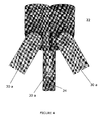
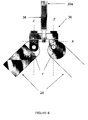
- Figure 6 shows a three-axis joint that allows rotation about three distinct, orthogonal axes X, Y, Z but constrains the pad rotations into synchronous movements.
- Two adjacent pads 28 are arranged to rotate around one common axis X in a synchronous manner.
- the joints 36 are used in a closed loop that constrains the rotation of all pads 28 mutually with respect to each other.
- One axis X is common to two adjacent pads ( Figure 6). This common axis forces any two adjacent pads 28 to tilt off the borehole-wall surface in a synchronous manner.
- the entire chain of pads forms a closed loop in which all pads around the perimeter must follow any such synchronous tilting motion.
- This synchronous tilt renders the entire pad loop more rigid and less susceptible to unwanted tilting of any single pad face off the borehole wall.
- the design mechanically forces the pad faces to stay mutually aligned in outward-facing orientation, regardless of hole size or inclination.
- a universal joint or some other type of skewed one- or two-axis rotation device may be used; however, any such alternative may not ensure the intrinsic rigidity of the closed pad loop against pad-tilt off the borehole wall.
- the pad mount is shown in Figure 6. It must permit the pads 28 to move freely as they spread around the hole perimeter between the radially spreading support arms. At the same time, the pad faces must be firmly oriented radially outward, avoiding any tilt against the borehole-wall surface as much as possible.
- the Z-axis rotations of all pads are independent. However, the X-rotation axis is shared by two adjacent pads. Thus, the tilt rotation of the said pad will be mechanically communicated to its neighbour pads.
- An X-rotation axis from an upper support arm 30 may support a tilt through an X-rotation by some angle ⁇ and a Z-rotation by some angle ⁇ , tilting the two attached pad faces both downward and toward each other (where the angle ⁇ is pointing in opposing directions for the two pads). Then the nearest-neighbour axes from the lower arms at the other end of the pads must rotate by the same angle ⁇ following the downward tilt of the pad face. Here, however, the Z-angle ⁇ is orienting the two faces away from each other. Successively, this tilt-rotation is communicated to the next pads beyond the nearest-neighbour pads through the X-rotation axis on the far side of the neighbour pads. This way, any tilt motion rigidly communicates around the entire pad loop.
- a universal tilt motion is still possible, since the number of pads in the loop is even.
- This universal tilt will be controlled by the average of the applied forces on the entire pad loop.
- a suitable mechanical design of these forces will serve to ensure that on average this tilt is zero and that the pad faces are parallel to the borehole wall.
- the bearing 40 on the sliding ring 32 for each arm is able to independently slide within the ring axially up or down over a limited range.
- This axial sliding action can be spring-controlled such that the ring (32) position is at the axial center of the various forces.
- the independently up-down sliding arm-bearings permit a pad deployment that extends beyond circular boreholes toward ovalized holes. The length of the axial-sliding freedom will determine the range of hole ovalization that can be supported.
- the arms of the tool 30 are pushed radially outward to the borehole wall and can be arranged to scrape the wall and so are provided with a hardened scraper plate 38 as an abrasion point.
- These scraper plates 38 can cut through the mud cake on the borehole wall and into the rock of the borehole wall itself.
- the point at the end of each arm may also be instrumented with a mm-resolution sensor, for example with a fluorescence-logging probe, an X-ray density probe or an infrared video-camera probe which can complement the measurement made via the pad.
- a modification of the tool embodiments described above include a detector of the angle ⁇ arm between the tool axis and any single radial support arm.
- Half-callipers obtained in this way for tools in which the upper and lower arms are fixed axially to the tool body 24 or sliding ring 32 are a variation of standard callipers.
- the calliper presented so far is limited to substantially circular holes due to the intrinsic rigidity of the assembly.
- the fact that the sliding ring 32 keeps all upward pointing arms at the same axial location as it slides up or down the tool body forces the closed pad chain into a circular ring without any ovalization.
- the bearing of the upward-pointing radial arms within the sliding ring 32 is modified.
- the support points of these arms are able to move over a limited interval axially along the ring, even as the ring itself is axially sliding up or down the tool.
- Equation (1) gives for each arm the radial half-calliper.
- the axial ring position Z ring measured from the top end of the sonde, and each axial arm position ⁇ Z arm , measured around the median value Z ring , are related to the half-calliper and thus provide an independent, complementary measurement to the radial angle ⁇ arm .
Landscapes
- Geology (AREA)
- Physics & Mathematics (AREA)
- Life Sciences & Earth Sciences (AREA)
- Engineering & Computer Science (AREA)
- Mining & Mineral Resources (AREA)
- General Life Sciences & Earth Sciences (AREA)
- Fluid Mechanics (AREA)
- Environmental & Geological Engineering (AREA)
- Geophysics (AREA)
- Geochemistry & Mineralogy (AREA)
- Geophysics And Detection Of Objects (AREA)
- Earth Drilling (AREA)
- Massaging Devices (AREA)
- Electrical Discharge Machining, Electrochemical Machining, And Combined Machining (AREA)
- Eye Examination Apparatus (AREA)
- Ultra Sonic Daignosis Equipment (AREA)
Priority Applications (6)
| Application Number | Priority Date | Filing Date | Title |
|---|---|---|---|
| AT04290744T ATE367509T1 (de) | 2004-03-18 | 2004-03-18 | Bohrlochvorrichtung |
| DE602004007619T DE602004007619T2 (de) | 2004-03-18 | 2004-03-18 | Bohrlochvorrichtung |
| EP04290744A EP1577488B8 (de) | 2004-03-18 | 2004-03-18 | Bohrlochvorrichtung |
| PCT/EP2005/001436 WO2005090752A1 (en) | 2004-03-18 | 2005-02-08 | Borehole tool |
| US10/598,941 US7409774B2 (en) | 2004-03-18 | 2005-02-08 | Borehole tool |
| CA2559676A CA2559676C (en) | 2004-03-18 | 2005-02-08 | Borehole tool |
Applications Claiming Priority (1)
| Application Number | Priority Date | Filing Date | Title |
|---|---|---|---|
| EP04290744A EP1577488B8 (de) | 2004-03-18 | 2004-03-18 | Bohrlochvorrichtung |
Publications (3)
| Publication Number | Publication Date |
|---|---|
| EP1577488A1 true EP1577488A1 (de) | 2005-09-21 |
| EP1577488B1 EP1577488B1 (de) | 2007-07-18 |
| EP1577488B8 EP1577488B8 (de) | 2009-02-18 |
Family
ID=34833799
Family Applications (1)
| Application Number | Title | Priority Date | Filing Date |
|---|---|---|---|
| EP04290744A Expired - Lifetime EP1577488B8 (de) | 2004-03-18 | 2004-03-18 | Bohrlochvorrichtung |
Country Status (6)
| Country | Link |
|---|---|
| US (1) | US7409774B2 (de) |
| EP (1) | EP1577488B8 (de) |
| AT (1) | ATE367509T1 (de) |
| CA (1) | CA2559676C (de) |
| DE (1) | DE602004007619T2 (de) |
| WO (1) | WO2005090752A1 (de) |
Cited By (1)
| Publication number | Priority date | Publication date | Assignee | Title |
|---|---|---|---|---|
| WO2012091803A3 (en) * | 2010-11-30 | 2012-10-26 | Schlumberger Canada Limited | Method and apparatus for logging a wellbore |
Families Citing this family (17)
| Publication number | Priority date | Publication date | Assignee | Title |
|---|---|---|---|---|
| JP2002055699A (ja) | 2000-08-10 | 2002-02-20 | Mitsubishi Electric Corp | 音声符号化装置および音声符号化方法 |
| US6711947B2 (en) | 2001-06-13 | 2004-03-30 | Rem Scientific Enterprises, Inc. | Conductive fluid logging sensor and method |
| CA2539249C (en) | 2003-10-01 | 2014-04-15 | Rem Scientific Enterprises, Inc. | Apparatus and method for fluid flow measurement with sensor shielding |
| GB2455685B (en) | 2006-11-10 | 2011-03-23 | Rem Scient Entpr Inc | Rotating fluid measurement device and method |
| US8327556B2 (en) * | 2008-04-11 | 2012-12-11 | The Secretary, Department Of Atomic Energy, Govt. Of India | Hydraulic micrometer system for remote measurement of inside diameter of pipes |
| US8237446B2 (en) * | 2008-08-27 | 2012-08-07 | Baker Hughes Incorporated | High resolution resistivity earth imager |
| CA2798565C (en) * | 2010-08-05 | 2016-04-05 | Liqui-Force Sewer Services, Inc. | Inspection device for measuring pipe size |
| WO2012166627A2 (en) * | 2011-05-27 | 2012-12-06 | Rem Scientific Enterprises, Inc. | Fluid flow measurement sensor, method, and analysis |
| US20130299687A1 (en) * | 2010-11-19 | 2013-11-14 | Schlumberger Technology Corporation | Neutron Wellbore Imaging Tool |
| CA2916015C (en) | 2013-08-30 | 2018-03-20 | Halliburton Energy Services, Inc. | Lwd resistivity imaging tool with adjustable sensor pads |
| US10295119B2 (en) * | 2014-06-30 | 2019-05-21 | Canrig Drilling Technology Ltd. | Ruggedized housing |
| US20160123130A1 (en) * | 2014-11-04 | 2016-05-05 | Schlumberger Technology Corporation | Borehole Tool |
| RU2601948C1 (ru) * | 2015-04-30 | 2016-11-10 | Коробейникова Валентина Александровна | Раскатчик скважин |
| CA3036228A1 (en) * | 2016-12-01 | 2018-06-07 | Halliburton Energy Services, Inc. | Translatable eat sensing modules and associated measurement methods |
| RU174391U1 (ru) * | 2017-06-21 | 2017-10-11 | Общество с ограниченной ответственностью "КАРСАР" | Башмак скважинного микросканера |
| US11371340B2 (en) * | 2018-12-07 | 2022-06-28 | Halliburton Energy Services, Inc. | Determination of borehole shape using standoff measurements |
| CN109989720B (zh) * | 2019-04-19 | 2021-04-02 | 王少斌 | 一种万向极板推靠器 |
Citations (8)
| Publication number | Priority date | Publication date | Assignee | Title |
|---|---|---|---|---|
| US4468623A (en) | 1981-07-30 | 1984-08-28 | Schlumberger Technology Corporation | Method and apparatus using pad carrying electrodes for electrically investigating a borehole |
| US4614250A (en) | 1981-09-09 | 1986-09-30 | Schlumberger Technology Corp. | Logging method and apparatus using a sonde equipped with measuring pads |
| US4692707A (en) | 1983-07-06 | 1987-09-08 | Schlumberger Technology Corporation | Method and apparatus for measuring the earth formation resistivity of a plurality of radial regions around a borehole |
| EP0285473A1 (de) | 1987-03-05 | 1988-10-05 | Societe De Prospection Electrique Schlumberger | Klappengerät für eine Explorationssonde |
| US5502686A (en) | 1994-08-01 | 1996-03-26 | Western Atlas International | Method and apparatus for imaging a borehole sidewall |
| US5631562A (en) * | 1994-03-31 | 1997-05-20 | Western Atlas International, Inc. | Time domain electromagnetic well logging sensor including arcuate microwave strip lines |
| WO2002101194A1 (en) * | 2001-06-13 | 2002-12-19 | Rem Scientific Enterprises, Inc. | Conductive fluid flow logging tool |
| US20030164706A1 (en) | 2002-01-14 | 2003-09-04 | Iwanicki William David | Method and apparatus for full offset resistivity imaging for use in boreholes |
Family Cites Families (6)
| Publication number | Priority date | Publication date | Assignee | Title |
|---|---|---|---|---|
| US2899633A (en) * | 1959-08-11 | Well logging device | ||
| US2267110A (en) * | 1940-07-18 | 1941-12-23 | Kinley | Surveying caliper |
| US3254221A (en) * | 1965-01-04 | 1966-05-31 | Schlumberger Well Surv Corp | Articulated gamma-gamma borehole logging apparatus |
| US3555689A (en) * | 1968-12-19 | 1971-01-19 | Schlumberger Technology Corp | Centralizing and well-calipering apparatus for well tools |
| US4121345A (en) * | 1977-04-13 | 1978-10-24 | Dresser Industries, Inc. | Linearly corrected articulated linkage for wellbore measuring instrument |
| WO1998012418A2 (en) * | 1996-09-23 | 1998-03-26 | Intelligent Inspection Corporation Commonwealth Of Massachusetts | Autonomous downhole oilfield tool |
-
2004
- 2004-03-18 DE DE602004007619T patent/DE602004007619T2/de not_active Expired - Lifetime
- 2004-03-18 AT AT04290744T patent/ATE367509T1/de not_active IP Right Cessation
- 2004-03-18 EP EP04290744A patent/EP1577488B8/de not_active Expired - Lifetime
-
2005
- 2005-02-08 US US10/598,941 patent/US7409774B2/en not_active Expired - Lifetime
- 2005-02-08 CA CA2559676A patent/CA2559676C/en not_active Expired - Fee Related
- 2005-02-08 WO PCT/EP2005/001436 patent/WO2005090752A1/en not_active Ceased
Patent Citations (9)
| Publication number | Priority date | Publication date | Assignee | Title |
|---|---|---|---|---|
| US4468623A (en) | 1981-07-30 | 1984-08-28 | Schlumberger Technology Corporation | Method and apparatus using pad carrying electrodes for electrically investigating a borehole |
| US4614250A (en) | 1981-09-09 | 1986-09-30 | Schlumberger Technology Corp. | Logging method and apparatus using a sonde equipped with measuring pads |
| US4692707A (en) | 1983-07-06 | 1987-09-08 | Schlumberger Technology Corporation | Method and apparatus for measuring the earth formation resistivity of a plurality of radial regions around a borehole |
| EP0285473A1 (de) | 1987-03-05 | 1988-10-05 | Societe De Prospection Electrique Schlumberger | Klappengerät für eine Explorationssonde |
| US4862090A (en) * | 1987-03-05 | 1989-08-29 | Schlumberger Technology Corporation | Measuring pad arrangement for a logging sonde |
| US5631562A (en) * | 1994-03-31 | 1997-05-20 | Western Atlas International, Inc. | Time domain electromagnetic well logging sensor including arcuate microwave strip lines |
| US5502686A (en) | 1994-08-01 | 1996-03-26 | Western Atlas International | Method and apparatus for imaging a borehole sidewall |
| WO2002101194A1 (en) * | 2001-06-13 | 2002-12-19 | Rem Scientific Enterprises, Inc. | Conductive fluid flow logging tool |
| US20030164706A1 (en) | 2002-01-14 | 2003-09-04 | Iwanicki William David | Method and apparatus for full offset resistivity imaging for use in boreholes |
Cited By (2)
| Publication number | Priority date | Publication date | Assignee | Title |
|---|---|---|---|---|
| WO2012091803A3 (en) * | 2010-11-30 | 2012-10-26 | Schlumberger Canada Limited | Method and apparatus for logging a wellbore |
| US8468882B2 (en) | 2010-11-30 | 2013-06-25 | Schlumberger Technology Corporation | Method and apparatus for logging a wellbore |
Also Published As
| Publication number | Publication date |
|---|---|
| ATE367509T1 (de) | 2007-08-15 |
| EP1577488B8 (de) | 2009-02-18 |
| WO2005090752A1 (en) | 2005-09-29 |
| US20070193776A1 (en) | 2007-08-23 |
| EP1577488B1 (de) | 2007-07-18 |
| US7409774B2 (en) | 2008-08-12 |
| DE602004007619D1 (de) | 2007-08-30 |
| CA2559676C (en) | 2012-01-03 |
| CA2559676A1 (en) | 2005-09-29 |
| DE602004007619T2 (de) | 2008-06-05 |
Similar Documents
| Publication | Publication Date | Title |
|---|---|---|
| EP1577488B1 (de) | Bohrlochvorrichtung | |
| EP2867463B1 (de) | Lwd-widerstandsbildgebungswerkzeug mit einstellbaren sensorpads | |
| EP1344091B1 (de) | Sensoren des lwd-typs (logging-while-drilling) mit rippenanbringung | |
| US7082994B2 (en) | Radially adjustable downhole devices and methods for same | |
| CA1280687C (en) | Flapper pad arrangement for logging sonde | |
| CA2539861C (en) | Modular downhole tool system | |
| US6600321B2 (en) | Apparatus and method for wellbore resistivity determination and imaging using capacitive coupling | |
| EP2611984A1 (de) | Blockierschutzvorrichtung für ein armsystem für bohrlochmessungen und anwendungsverfahren dafür | |
| MX2013002387A (es) | Un sistema de brazos para el registro de un hoyo y un método para usar el mismo. | |
| US20230243220A1 (en) | Adaptive Control of Rotating or Non-Rotating Transducer and Sensors Casing Stand-Off Supported by Casing Centralizers | |
| EP0703349B1 (de) | Verfahren und Vorrichtung für Bohrlochmessungen in unrunden Bohrlöchern | |
| CA2447508A1 (en) | Method and apparatus for obtaining electrical images of a borehole wall through nonconductive mud | |
| US12116850B1 (en) | Device for centering a sensor assembly in a bore | |
| US8446150B2 (en) | Apparatus and method for logging in boreholes with a non-circular section |
Legal Events
| Date | Code | Title | Description |
|---|---|---|---|
| PUAI | Public reference made under article 153(3) epc to a published international application that has entered the european phase |
Free format text: ORIGINAL CODE: 0009012 |
|
| AK | Designated contracting states |
Kind code of ref document: A1 Designated state(s): AT BE BG CH CY CZ DE DK EE ES FI FR GB GR HU IE IT LI LU MC NL PL PT RO SE SI SK TR |
|
| AX | Request for extension of the european patent |
Extension state: AL LT LV MK |
|
| 17P | Request for examination filed |
Effective date: 20060127 |
|
| AKX | Designation fees paid |
Designated state(s): AT BE BG CH CY CZ DE DK EE ES FI FR GB GR HU IE IT LI LU MC NL PL PT RO SE SI SK TR |
|
| GRAP | Despatch of communication of intention to grant a patent |
Free format text: ORIGINAL CODE: EPIDOSNIGR1 |
|
| GRAS | Grant fee paid |
Free format text: ORIGINAL CODE: EPIDOSNIGR3 |
|
| GRAA | (expected) grant |
Free format text: ORIGINAL CODE: 0009210 |
|
| AK | Designated contracting states |
Kind code of ref document: B1 Designated state(s): AT BE BG CH CY CZ DE DK EE ES FI FR GB GR HU IE IT LI LU MC NL PL PT RO SE SI SK TR |
|
| REG | Reference to a national code |
Ref country code: GB Ref legal event code: FG4D |
|
| REG | Reference to a national code |
Ref country code: CH Ref legal event code: EP |
|
| REF | Corresponds to: |
Ref document number: 602004007619 Country of ref document: DE Date of ref document: 20070830 Kind code of ref document: P |
|
| REG | Reference to a national code |
Ref country code: IE Ref legal event code: FG4D |
|
| ET | Fr: translation filed | ||
| PG25 | Lapsed in a contracting state [announced via postgrant information from national office to epo] |
Ref country code: BG Free format text: LAPSE BECAUSE OF FAILURE TO SUBMIT A TRANSLATION OF THE DESCRIPTION OR TO PAY THE FEE WITHIN THE PRESCRIBED TIME-LIMIT Effective date: 20071018 Ref country code: FI Free format text: LAPSE BECAUSE OF FAILURE TO SUBMIT A TRANSLATION OF THE DESCRIPTION OR TO PAY THE FEE WITHIN THE PRESCRIBED TIME-LIMIT Effective date: 20070718 Ref country code: ES Free format text: LAPSE BECAUSE OF FAILURE TO SUBMIT A TRANSLATION OF THE DESCRIPTION OR TO PAY THE FEE WITHIN THE PRESCRIBED TIME-LIMIT Effective date: 20071029 Ref country code: PT Free format text: LAPSE BECAUSE OF FAILURE TO SUBMIT A TRANSLATION OF THE DESCRIPTION OR TO PAY THE FEE WITHIN THE PRESCRIBED TIME-LIMIT Effective date: 20071218 |
|
| REG | Reference to a national code |
Ref country code: CH Ref legal event code: PL |
|
| PG25 | Lapsed in a contracting state [announced via postgrant information from national office to epo] |
Ref country code: PL Free format text: LAPSE BECAUSE OF FAILURE TO SUBMIT A TRANSLATION OF THE DESCRIPTION OR TO PAY THE FEE WITHIN THE PRESCRIBED TIME-LIMIT Effective date: 20070718 Ref country code: LI Free format text: LAPSE BECAUSE OF FAILURE TO SUBMIT A TRANSLATION OF THE DESCRIPTION OR TO PAY THE FEE WITHIN THE PRESCRIBED TIME-LIMIT Effective date: 20070718 Ref country code: CH Free format text: LAPSE BECAUSE OF FAILURE TO SUBMIT A TRANSLATION OF THE DESCRIPTION OR TO PAY THE FEE WITHIN THE PRESCRIBED TIME-LIMIT Effective date: 20070718 Ref country code: AT Free format text: LAPSE BECAUSE OF FAILURE TO SUBMIT A TRANSLATION OF THE DESCRIPTION OR TO PAY THE FEE WITHIN THE PRESCRIBED TIME-LIMIT Effective date: 20070718 |
|
| PG25 | Lapsed in a contracting state [announced via postgrant information from national office to epo] |
Ref country code: BE Free format text: LAPSE BECAUSE OF FAILURE TO SUBMIT A TRANSLATION OF THE DESCRIPTION OR TO PAY THE FEE WITHIN THE PRESCRIBED TIME-LIMIT Effective date: 20070718 |
|
| PG25 | Lapsed in a contracting state [announced via postgrant information from national office to epo] |
Ref country code: DK Free format text: LAPSE BECAUSE OF FAILURE TO SUBMIT A TRANSLATION OF THE DESCRIPTION OR TO PAY THE FEE WITHIN THE PRESCRIBED TIME-LIMIT Effective date: 20070718 Ref country code: GR Free format text: LAPSE BECAUSE OF FAILURE TO SUBMIT A TRANSLATION OF THE DESCRIPTION OR TO PAY THE FEE WITHIN THE PRESCRIBED TIME-LIMIT Effective date: 20071019 |
|
| PLBE | No opposition filed within time limit |
Free format text: ORIGINAL CODE: 0009261 |
|
| STAA | Information on the status of an ep patent application or granted ep patent |
Free format text: STATUS: NO OPPOSITION FILED WITHIN TIME LIMIT |
|
| PG25 | Lapsed in a contracting state [announced via postgrant information from national office to epo] |
Ref country code: SK Free format text: LAPSE BECAUSE OF FAILURE TO SUBMIT A TRANSLATION OF THE DESCRIPTION OR TO PAY THE FEE WITHIN THE PRESCRIBED TIME-LIMIT Effective date: 20070718 |
|
| 26N | No opposition filed |
Effective date: 20080421 |
|
| PG25 | Lapsed in a contracting state [announced via postgrant information from national office to epo] |
Ref country code: SE Free format text: LAPSE BECAUSE OF FAILURE TO SUBMIT A TRANSLATION OF THE DESCRIPTION OR TO PAY THE FEE WITHIN THE PRESCRIBED TIME-LIMIT Effective date: 20071018 Ref country code: RO Free format text: LAPSE BECAUSE OF FAILURE TO SUBMIT A TRANSLATION OF THE DESCRIPTION OR TO PAY THE FEE WITHIN THE PRESCRIBED TIME-LIMIT Effective date: 20070718 |
|
| PG25 | Lapsed in a contracting state [announced via postgrant information from national office to epo] |
Ref country code: MC Free format text: LAPSE BECAUSE OF NON-PAYMENT OF DUE FEES Effective date: 20080331 |
|
| RAP2 | Party data changed (patent owner data changed or rights of a patent transferred) |
Owner name: SERVICES PETROLIERS SCHLUMBERGER Owner name: SCHLUMBERGER TECHNOLOGY B.V. Owner name: SCHLUMBERGER HOLDINGS LIMITED |
|
| PG25 | Lapsed in a contracting state [announced via postgrant information from national office to epo] |
Ref country code: IE Free format text: LAPSE BECAUSE OF NON-PAYMENT OF DUE FEES Effective date: 20080318 Ref country code: EE Free format text: LAPSE BECAUSE OF FAILURE TO SUBMIT A TRANSLATION OF THE DESCRIPTION OR TO PAY THE FEE WITHIN THE PRESCRIBED TIME-LIMIT Effective date: 20070718 |
|
| NLT2 | Nl: modifications (of names), taken from the european patent patent bulletin |
Owner name: SCHLUMBERGER HOLDINGS LIMITED Effective date: 20090121 |
|
| PG25 | Lapsed in a contracting state [announced via postgrant information from national office to epo] |
Ref country code: CZ Free format text: LAPSE BECAUSE OF FAILURE TO SUBMIT A TRANSLATION OF THE DESCRIPTION OR TO PAY THE FEE WITHIN THE PRESCRIBED TIME-LIMIT Effective date: 20070718 |
|
| PG25 | Lapsed in a contracting state [announced via postgrant information from national office to epo] |
Ref country code: SI Free format text: LAPSE BECAUSE OF FAILURE TO SUBMIT A TRANSLATION OF THE DESCRIPTION OR TO PAY THE FEE WITHIN THE PRESCRIBED TIME-LIMIT Effective date: 20070718 |
|
| PG25 | Lapsed in a contracting state [announced via postgrant information from national office to epo] |
Ref country code: CY Free format text: LAPSE BECAUSE OF FAILURE TO SUBMIT A TRANSLATION OF THE DESCRIPTION OR TO PAY THE FEE WITHIN THE PRESCRIBED TIME-LIMIT Effective date: 20070718 |
|
| PG25 | Lapsed in a contracting state [announced via postgrant information from national office to epo] |
Ref country code: LU Free format text: LAPSE BECAUSE OF NON-PAYMENT OF DUE FEES Effective date: 20080318 Ref country code: HU Free format text: LAPSE BECAUSE OF FAILURE TO SUBMIT A TRANSLATION OF THE DESCRIPTION OR TO PAY THE FEE WITHIN THE PRESCRIBED TIME-LIMIT Effective date: 20080119 |
|
| PG25 | Lapsed in a contracting state [announced via postgrant information from national office to epo] |
Ref country code: TR Free format text: LAPSE BECAUSE OF FAILURE TO SUBMIT A TRANSLATION OF THE DESCRIPTION OR TO PAY THE FEE WITHIN THE PRESCRIBED TIME-LIMIT Effective date: 20070718 |
|
| PGFP | Annual fee paid to national office [announced via postgrant information from national office to epo] |
Ref country code: NL Payment date: 20140308 Year of fee payment: 11 |
|
| PGFP | Annual fee paid to national office [announced via postgrant information from national office to epo] |
Ref country code: IT Payment date: 20140317 Year of fee payment: 11 |
|
| REG | Reference to a national code |
Ref country code: FR Ref legal event code: PLFP Year of fee payment: 12 |
|
| PGFP | Annual fee paid to national office [announced via postgrant information from national office to epo] |
Ref country code: DE Payment date: 20150310 Year of fee payment: 12 |
|
| PGFP | Annual fee paid to national office [announced via postgrant information from national office to epo] |
Ref country code: FR Payment date: 20150309 Year of fee payment: 12 |
|
| REG | Reference to a national code |
Ref country code: NL Ref legal event code: MM Effective date: 20150401 |
|
| PG25 | Lapsed in a contracting state [announced via postgrant information from national office to epo] |
Ref country code: IT Free format text: LAPSE BECAUSE OF NON-PAYMENT OF DUE FEES Effective date: 20150318 |
|
| PGFP | Annual fee paid to national office [announced via postgrant information from national office to epo] |
Ref country code: GB Payment date: 20160316 Year of fee payment: 13 |
|
| REG | Reference to a national code |
Ref country code: DE Ref legal event code: R119 Ref document number: 602004007619 Country of ref document: DE |
|
| REG | Reference to a national code |
Ref country code: FR Ref legal event code: ST Effective date: 20161130 |
|
| PG25 | Lapsed in a contracting state [announced via postgrant information from national office to epo] |
Ref country code: FR Free format text: LAPSE BECAUSE OF NON-PAYMENT OF DUE FEES Effective date: 20160331 Ref country code: DE Free format text: LAPSE BECAUSE OF NON-PAYMENT OF DUE FEES Effective date: 20161001 |
|
| PG25 | Lapsed in a contracting state [announced via postgrant information from national office to epo] |
Ref country code: NL Free format text: LAPSE BECAUSE OF NON-PAYMENT OF DUE FEES Effective date: 20150401 |
|
| GBPC | Gb: european patent ceased through non-payment of renewal fee |
Effective date: 20170318 |
|
| PG25 | Lapsed in a contracting state [announced via postgrant information from national office to epo] |
Ref country code: GB Free format text: LAPSE BECAUSE OF NON-PAYMENT OF DUE FEES Effective date: 20170318 |
|
| P01 | Opt-out of the competence of the unified patent court (upc) registered |
Effective date: 20231208 |