EP1577505A2 - Pontet de positionnement et son utilisation au canal support de tuyere d'un turbopropulseur - Google Patents
Pontet de positionnement et son utilisation au canal support de tuyere d'un turbopropulseur Download PDFInfo
- Publication number
- EP1577505A2 EP1577505A2 EP05102022A EP05102022A EP1577505A2 EP 1577505 A2 EP1577505 A2 EP 1577505A2 EP 05102022 A EP05102022 A EP 05102022A EP 05102022 A EP05102022 A EP 05102022A EP 1577505 A2 EP1577505 A2 EP 1577505A2
- Authority
- EP
- European Patent Office
- Prior art keywords
- positioning
- contact
- thermal protection
- arched
- constituting
- Prior art date
- Legal status (The legal status is an assumption and is not a legal conclusion. Google has not performed a legal analysis and makes no representation as to the accuracy of the status listed.)
- Granted
Links
Images
Classifications
-
- F—MECHANICAL ENGINEERING; LIGHTING; HEATING; WEAPONS; BLASTING
- F01—MACHINES OR ENGINES IN GENERAL; ENGINE PLANTS IN GENERAL; STEAM ENGINES
- F01D—NON-POSITIVE DISPLACEMENT MACHINES OR ENGINES, e.g. STEAM TURBINES
- F01D25/00—Component parts, details, or accessories, not provided for in, or of interest apart from, other groups
- F01D25/24—Casings; Casing parts, e.g. diaphragms, casing fastenings
-
- F—MECHANICAL ENGINEERING; LIGHTING; HEATING; WEAPONS; BLASTING
- F02—COMBUSTION ENGINES; HOT-GAS OR COMBUSTION-PRODUCT ENGINE PLANTS
- F02C—GAS-TURBINE PLANTS; AIR INTAKES FOR JET-PROPULSION PLANTS; CONTROLLING FUEL SUPPLY IN AIR-BREATHING JET-PROPULSION PLANTS
- F02C7/00—Features, components parts, details or accessories, not provided for in, or of interest apart form groups F02C1/00 - F02C6/00; Air intakes for jet-propulsion plants
- F02C7/20—Mounting or supporting of plant; Accommodating heat expansion or creep
-
- F—MECHANICAL ENGINEERING; LIGHTING; HEATING; WEAPONS; BLASTING
- F02—COMBUSTION ENGINES; HOT-GAS OR COMBUSTION-PRODUCT ENGINE PLANTS
- F02K—JET-PROPULSION PLANTS
- F02K1/00—Plants characterised by the form or arrangement of the jet pipe or nozzle; Jet pipes or nozzles peculiar thereto
- F02K1/78—Other construction of jet pipes
- F02K1/82—Jet pipe walls, e.g. liners
- F02K1/822—Heat insulating structures or liners, cooling arrangements, e.g. post combustion liners; Infrared radiation suppressors
-
- F—MECHANICAL ENGINEERING; LIGHTING; HEATING; WEAPONS; BLASTING
- F05—INDEXING SCHEMES RELATING TO ENGINES OR PUMPS IN VARIOUS SUBCLASSES OF CLASSES F01-F04
- F05D—INDEXING SCHEME FOR ASPECTS RELATING TO NON-POSITIVE-DISPLACEMENT MACHINES OR ENGINES, GAS-TURBINES OR JET-PROPULSION PLANTS
- F05D2230/00—Manufacture
- F05D2230/60—Assembly methods
- F05D2230/64—Assembly methods using positioning or alignment devices for aligning or centring, e.g. pins
- F05D2230/642—Assembly methods using positioning or alignment devices for aligning or centring, e.g. pins using maintaining alignment while permitting differential dilatation
-
- Y—GENERAL TAGGING OF NEW TECHNOLOGICAL DEVELOPMENTS; GENERAL TAGGING OF CROSS-SECTIONAL TECHNOLOGIES SPANNING OVER SEVERAL SECTIONS OF THE IPC; TECHNICAL SUBJECTS COVERED BY FORMER USPC CROSS-REFERENCE ART COLLECTIONS [XRACs] AND DIGESTS
- Y02—TECHNOLOGIES OR APPLICATIONS FOR MITIGATION OR ADAPTATION AGAINST CLIMATE CHANGE
- Y02T—CLIMATE CHANGE MITIGATION TECHNOLOGIES RELATED TO TRANSPORTATION
- Y02T50/00—Aeronautics or air transport
- Y02T50/60—Efficient propulsion technologies, e.g. for aircraft
Definitions
- the invention relates to the field of turboprop used in aeronautics, and more precisely the relative positioning of the shirt of thermal protection and the nozzle support channel of a propellant, in particular a flow propellant secondary cooling.
- the bridges are riveted on the thermal protection jacket, a spot welding sometimes resulting in cutaways.
- the main disadvantage of this solution is the lack of flexibility. Indeed, under a compression load due to a difference in thermal expansion and a pressure differential between the nozzle support channel and the nozzle sleeve thermal protection, the amounts of the jumpers are quickly braced and the maximum stress eligible is quickly reached.
- the risks associated with this lack of flexibility are, among others, the postponement of deformation on the nozzle support channel and the thermal protection jacket. Now, these pieces are complex, expensive and likely to cause malfunctions of the turboprop, if they are deteriorated. We think in particular of the implosion of the thermal protection jacket that causes a partial obstruction of the primary motor flow, local draws of the nozzle support channel and associated breaks.
- a solution composed of bridges of very low height fixed on a circular diaphragm riveted on the shirt is more flexible of operation.
- the thermal gradient between upstream and downstream of the diaphragm does not give satisfaction with the engine structure. In effect, it was found a thermal fatigue causing longitudinal cracks and then circumferential until a loss of portions of area.
- the object of the invention is to remedy disadvantages mentioned above and to propose another type of trigger guard, knowing that the jumpers must ensure three main functions.
- the first is to ideally touch as soon as possible the support channel of nozzle, in order to center the protective sleeve thermal. It is noted that an increase in the number support increases the buckling capacity of the thermal protection jacket.
- a second function is to make it possible to calibrate the sections of diaphragms in the secondary flow.
- the third is the absorption of dilations differential and multidirectional important to this level of turboprop.
- the central part arched has an inverted central arch, thus defining two summit areas constituting two points of contact with the second of two rooms.
- a preferred embodiment consists also to equip the junction between the central part arched and the legs of a small radius of curvature.
- a second main object of the invention is a device for positioning and adapting to differential dilations between the shirt of thermal protection and the envelope of the support channel of nozzle of a turbojet.
- bridges are used including the previously stated characteristics and attached to the thermal protection jacket.
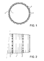
- Figure 1 shows the implantation circumferential bridges 3 according to the invention on a thermal protection jacket 1 of a nozzle of turboprop.
- Both fine lines interrupted 2 symbolize the extreme positions of the envelope the nozzle support channel.
- space between the thermal protection jacket 1 and the envelope of the secondary flow channel 2 is the order of 10 mm.
- the bridges 3 are relatively flat. However, they must be able to withstand a crush of the order of 15 to 25% of the height, while ensuring a mechanical hold sufficient.
- Figure 2 shows the positioning length of the bridges on the protective cover thermal 1 of the nozzle of a turboprop. It is so possible and easily achievable to put several rows or rings of bridges 3 all over the length of this piece to ensure positioning of the secondary flow channel envelope all over its length.
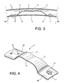
- Figure 3 shows in more detail the shape bridges 3, in particular their central arched portion 8 surrounded by two legs 5A and 5B. These are in contact with the heat shield 1.
- the shape of the arched central part 8 is therefore characterized by two summit areas 4 which extend to the legs 5A and 5B. Both zones 4 are each a point of contact privileged with the envelope of the secondary flow channel 2 (in this figure 3, the position of it has been represented in interrupted fine lines).
- the arched central part 8 presents a inverted arch versus curvature of areas 4. This central camber geometry inverted allows to obtain a bending capacity markedly increased from each trigger guard. Indeed, bridges according to the uses of the prior art enjoy only a very limited flexibility on the amounts of the trigger guard.
- Another complementary feature to the inverted arch of the arched central part 8 is the small radius of curvature of the junctions 9 between this arched central portion 8 and the legs 5A and 5B.
- the flexion zone is optimized in the arched central portion 8 of the trigger guard. Bending can so take place thanks to the inverted arch that orients flexion by favoring a direction of deformation. This allows, in addition, the use of the instability of the geometry. It is thus possible to absorb radial differential dilatation between two pieces by tangential bending.
- the entire trigger guard is in contact with the thermal protection jacket 1 by a fixation of the left leg 5A by means of rivet 6 and by means of a guiding pin 7 which provides a degree of freedom of the tab 5B, relative to the protective jacket 1.
- the left leg 5A is provided with holes fixture 10 to be fixed integrally to the thermal protection jacket 1. It is specified that as the trigger guard is made from a blade relatively large metal.
- the right leg 5B is provided with a light 11 whose axis is parallel to the axis longitudinal blade constituting the trigger guard.
- a pawn 7 is fixed in the protective jacket thermal and at a T shape. The head of the T exceeds above the light 11, while the foot of the T is inserted inside it.
- the trigger guard may be subject to variations in length in the longitudinal direction, due to significant differences temperature compared to those experienced by the thermal protection shirt 1.
- the pawn of guide 7 can move in the longitudinal direction of the light 11 and allow relative movement in this direction of the trigger guard by the thermal protection jacket.
- this link to a degree of freedom a limit the constraints in the trigger guard.
- the trigger guard plays its role of damping in an optimized way and thus limits the risks of damage to the shirt of thermal protection and support channel envelope of nozzle which are very clearly more parts costly than the bridge thus proposed. Indeed, it is the latter which absorbs almost all deformations during the operation of the turbojet. It plays a role of fuse. We also notes that the blazing capacity of the thermal protection shirt is increased by the use of such bridges.
Landscapes
- Engineering & Computer Science (AREA)
- Mechanical Engineering (AREA)
- General Engineering & Computer Science (AREA)
- Chemical & Material Sciences (AREA)
- Combustion & Propulsion (AREA)
- Turbine Rotor Nozzle Sealing (AREA)
- Structures Of Non-Positive Displacement Pumps (AREA)
- Supercharger (AREA)
- Cylinder Crankcases Of Internal Combustion Engines (AREA)
Abstract
Description
- deux pattes constituées par les deux extrémités de la lame, devant être en contact avec une première des deux pièces ;
- une partie centrale cambrée reliant les deux pattes, et comprenant au moins une zone sommitale de la cambrure constituant au moins une zone de contact avec la deuxième des deux pièces.
- figure 1, le positionnement circonférentielle dans l'utilisation des pontets selon l'invention pour un turbopropulseur ;
- figure 2, le positionnement longitudinal des pontets selon l'invention dans cette même utilisation pour un turbopropulseur ;
- figure 3, en coupe, un pontet selon l'invention positionné pour son utilisation dans un turbopropulseur ; et
- figure 4, en vue cavalière, un pontet selon l'invention.
Claims (6)
- Pontet de positionnement de deux pièces (1, 2) l'une par rapport à l'autre susceptibles de variations de leur position relative, constitué d'une lame métallique comportant principalement :caractérisé en ce que la partie centrale cambrée (8) présente une cambrure centrale inversée définissant ainsi deux zones sommitales (4) constituant deux points de contact avec la deuxième (2) des deux pièces.deux pattes (5A, 5B) constituées par chacune par une extrémité de la lame, devant être en contact sur une première (1) des deux pièces (1, 2) ; etune partie centrale cambrée (8) reliant les deux pattes (5A, 5B) ayant au moins une zone sommitale (4) de la partie centrale cambrée (8) et constituant ainsi au moins une zone de contact avec la deuxième (2) des deux pièces,
- Pontet de positionnement selon la revendication 1, caractérisé en ce qu'une seule des deux pattes (5A) est fixée sur la première pièce (1), l'autre patte (5B) n'étant qu'en contact avec cette première pièce (1) pour avoir un mouvement tangentiel relatif à la première pièce.
- Pontet de positionnement selon la revendication 2, caractérisé en ce qu'il comprend une lumière (11) dans la deuxième patte (5B) dans le sens longitudinal de la lame constituant le pontet.
- Pontet de positionnement selon la revendication 3, caractérisé en ce qu'il comprend un pion de guidage en T (7) solidaire de la première pièce (1) et dont le pied du T est placé dans la lumière (11) .
- Pontet de positionnement selon la revendication 1, caractérisé en ce que il comprend des parties de liaison (9) entre les pattes (5A, 5B) et la partie centrale cambrée (8) de faible rayon de courbure.
- Dispositif de positionnement et d'adaptation aux dilatations différentielles entre la chemise de protection thermique (1) et l'enveloppe du canal support de tuyère (2) d'un turbopropulseur,
caractérisé en ce qu'il comprend un certain nombre de pontets (3) selon l'une des revendications précédentes, fixé sur l'enveloppe de protection thermique par la première des deux pattes (5A).
Applications Claiming Priority (2)
| Application Number | Priority Date | Filing Date | Title |
|---|---|---|---|
| FR0450518A FR2867507B1 (fr) | 2004-03-15 | 2004-03-15 | Pontet de positionnement et son utilisation au canal support de tuyere d'un turbopropulseur |
| FR0450518 | 2004-03-15 |
Publications (3)
| Publication Number | Publication Date |
|---|---|
| EP1577505A2 true EP1577505A2 (fr) | 2005-09-21 |
| EP1577505A3 EP1577505A3 (fr) | 2013-08-07 |
| EP1577505B1 EP1577505B1 (fr) | 2014-11-12 |
Family
ID=34834276
Family Applications (1)
| Application Number | Title | Priority Date | Filing Date |
|---|---|---|---|
| EP05102022.0A Expired - Lifetime EP1577505B1 (fr) | 2004-03-15 | 2005-03-15 | Pontet de positionnement et son utilisation au canal support de tuyere d'un turbopropulseur |
Country Status (5)
| Country | Link |
|---|---|
| US (1) | US7614236B2 (fr) |
| EP (1) | EP1577505B1 (fr) |
| JP (1) | JP4630697B2 (fr) |
| FR (1) | FR2867507B1 (fr) |
| RU (1) | RU2364730C2 (fr) |
Cited By (6)
| Publication number | Priority date | Publication date | Assignee | Title |
|---|---|---|---|---|
| EP2031303A1 (fr) * | 2007-08-30 | 2009-03-04 | Snecma | Turbomachine à chambre annulaire de combustion |
| DE102010010712A1 (de) * | 2010-03-08 | 2011-09-08 | Rolls-Royce Deutschland Ltd & Co Kg | Halter zur Montage von Anbauteilen am Gehäuse eines Triebwerks, insbesondere eines Strahltriebwerks |
| WO2012161905A3 (fr) * | 2011-05-20 | 2013-12-19 | Siemens Energy, Inc. | Support thermiquement compatible pour un système de combustion |
| US8866084B2 (en) | 2012-09-06 | 2014-10-21 | Siemens Energy, Inc. | Infrared non-destructive evaluation method and apparatus |
| CN110050115A (zh) * | 2017-02-28 | 2019-07-23 | 三菱重工发动机和增压器株式会社 | 排气涡轮增压器 |
| CN110925792A (zh) * | 2019-11-06 | 2020-03-27 | 西北工业大学 | 一种带分层排列离心式喷嘴的燃油总管 |
Families Citing this family (13)
| Publication number | Priority date | Publication date | Assignee | Title |
|---|---|---|---|---|
| PL2574900T3 (pl) * | 2011-09-30 | 2015-11-30 | Mettler Toledo Gmbh | Przyrząd pomiarowy do grawimetrycznego wyznaczania wilgotności |
| US10054080B2 (en) | 2012-10-22 | 2018-08-21 | United Technologies Corporation | Coil spring hanger for exhaust duct liner |
| GB201302125D0 (en) * | 2013-02-07 | 2013-03-20 | Rolls Royce Plc | A panel mounting arrangement |
| ES2723400T3 (es) | 2015-12-07 | 2019-08-27 | MTU Aero Engines AG | Estructura de carcasa de una turbomáquina con pantalla de protección térmica |
| US10427778B2 (en) * | 2016-03-14 | 2019-10-01 | The Boeing Company | Heat shield assembly and method |
| US10260360B2 (en) * | 2016-03-24 | 2019-04-16 | General Electric Company | Transition duct assembly |
| KR101760736B1 (ko) * | 2016-06-15 | 2017-07-31 | 두산중공업 주식회사 | 가스터빈용 연소 덕트를 조립하기 위한 스프링 플레이트 |
| CN106988850A (zh) * | 2017-03-15 | 2017-07-28 | 中国航空工业集团公司西安飞机设计研究所 | 一种飞机发动机排气管及具有其的飞机 |
| KR101787081B1 (ko) * | 2017-07-13 | 2017-11-15 | 두산중공업 주식회사 | 스프링 플레이트를 구비하는 가스터빈용 연소 덕트 조립체 |
| US11002153B2 (en) | 2018-07-10 | 2021-05-11 | Raytheon Technologies Corporation | Balance bracket |
| US12252245B2 (en) | 2021-01-20 | 2025-03-18 | The Boeing Company | Beaded composite structures and methods for manufacturing beaded composite structures |
| CN113775419B (zh) * | 2021-11-11 | 2022-03-08 | 中国航发四川燃气涡轮研究院 | 一种可适应不同方向热变形的挂钩式连接结构 |
| CN115507393A (zh) * | 2022-09-20 | 2022-12-23 | 中国联合重型燃气轮机技术有限公司 | 筒体支撑件、燃气轮机燃烧室和燃气轮机 |
Family Cites Families (22)
| Publication number | Priority date | Publication date | Assignee | Title |
|---|---|---|---|---|
| US2794319A (en) * | 1953-03-02 | 1957-06-04 | Westinghouse Electric Corp | Afterburner shell construction |
| US2795108A (en) * | 1953-10-07 | 1957-06-11 | Westinghouse Electric Corp | Combustion apparatus |
| US2962053A (en) * | 1958-03-10 | 1960-11-29 | Epstein Saul | Spacer for triple wall vent pipe |
| US3398527A (en) * | 1966-05-31 | 1968-08-27 | Air Force Usa | Corrugated wall radiation cooled combustion chamber |
| FR2191025B1 (fr) * | 1972-07-04 | 1975-03-07 | Aerospatiale | |
| US4833881A (en) * | 1984-12-17 | 1989-05-30 | General Electric Company | Gas turbine engine augmentor |
| US4718230A (en) * | 1986-11-10 | 1988-01-12 | United Technologies Corporation | Augmentor liner construction |
| US4848089A (en) * | 1988-02-18 | 1989-07-18 | Avco Corporation | Combustor attachment device |
| US4864818A (en) * | 1988-04-07 | 1989-09-12 | United Technologies Corporation | Augmentor liner construction |
| FR2646880A1 (fr) * | 1989-05-11 | 1990-11-16 | Snecma | Chemise de protection thermique pour canal de post-combustion ou de transition d'un turboreacteur |
| GB9127505D0 (en) * | 1991-03-11 | 2013-12-25 | Gen Electric | Multi-hole film cooled afterburner combustor liner |
| US5144795A (en) * | 1991-05-14 | 1992-09-08 | The United States Of America As Represented By The Secretary Of The Air Force | Fluid cooled hot duct liner structure |
| US5201887A (en) * | 1991-11-26 | 1993-04-13 | United Technologies Corporation | Damper for augmentor liners |
| US5337583A (en) * | 1992-08-24 | 1994-08-16 | United Technologies Corporation | Replaceable clip |
| GB9623615D0 (en) * | 1996-11-13 | 1997-07-09 | Rolls Royce Plc | Jet pipe liner |
| US6199371B1 (en) * | 1998-10-15 | 2001-03-13 | United Technologies Corporation | Thermally compliant liner |
| JP2000320303A (ja) * | 1999-05-07 | 2000-11-21 | Ishikawajima Harima Heavy Ind Co Ltd | タービン静翼構造体 |
| DE10010580A1 (de) * | 2000-03-03 | 2001-09-06 | Opel Adam Ag | Vorrichtung zum Verbinden von zwei Bauteilen mit unterschiedlichem Wärmeausdehnungsverhalten |
| FR2817285B1 (fr) * | 2000-11-30 | 2003-06-13 | Snecma Moteurs | Virole interne de stator |
| JP3600911B2 (ja) * | 2001-01-25 | 2004-12-15 | 川崎重工業株式会社 | 環状燃焼器のライナ支持構造 |
| US6394537B1 (en) * | 2001-01-31 | 2002-05-28 | Daimlerchrysler Corporation | Arrangement for attaching a plastic vehicle body to a metal frame and related method |
| US6655147B2 (en) * | 2002-04-10 | 2003-12-02 | General Electric Company | Annular one-piece corrugated liner for combustor of a gas turbine engine |
-
2004
- 2004-03-15 FR FR0450518A patent/FR2867507B1/fr not_active Expired - Lifetime
-
2005
- 2005-03-10 US US11/075,851 patent/US7614236B2/en not_active Expired - Lifetime
- 2005-03-14 JP JP2005070587A patent/JP4630697B2/ja not_active Expired - Lifetime
- 2005-03-14 RU RU2005107141/06A patent/RU2364730C2/ru active
- 2005-03-15 EP EP05102022.0A patent/EP1577505B1/fr not_active Expired - Lifetime
Cited By (10)
| Publication number | Priority date | Publication date | Assignee | Title |
|---|---|---|---|---|
| EP2031303A1 (fr) * | 2007-08-30 | 2009-03-04 | Snecma | Turbomachine à chambre annulaire de combustion |
| DE102010010712A1 (de) * | 2010-03-08 | 2011-09-08 | Rolls-Royce Deutschland Ltd & Co Kg | Halter zur Montage von Anbauteilen am Gehäuse eines Triebwerks, insbesondere eines Strahltriebwerks |
| DE102010010712B4 (de) | 2010-03-08 | 2018-08-02 | Rolls-Royce Deutschland Ltd & Co Kg | Halter zur Montage von Anbauteilen am Gehäuse eines Triebwerks, insbesondere eines Strahltriebwerks |
| WO2012161905A3 (fr) * | 2011-05-20 | 2013-12-19 | Siemens Energy, Inc. | Support thermiquement compatible pour un système de combustion |
| US9803868B2 (en) | 2011-05-20 | 2017-10-31 | Siemens Energy, Inc. | Thermally compliant support for a combustion system |
| US8866084B2 (en) | 2012-09-06 | 2014-10-21 | Siemens Energy, Inc. | Infrared non-destructive evaluation method and apparatus |
| CN110050115A (zh) * | 2017-02-28 | 2019-07-23 | 三菱重工发动机和增压器株式会社 | 排气涡轮增压器 |
| US10890105B2 (en) | 2017-02-28 | 2021-01-12 | Mitsubishi Heavy Industries Engine & Turbocharger, Ltd. | Exhaust gas turbocharger |
| CN110050115B (zh) * | 2017-02-28 | 2021-05-14 | 三菱重工发动机和增压器株式会社 | 排气涡轮增压器 |
| CN110925792A (zh) * | 2019-11-06 | 2020-03-27 | 西北工业大学 | 一种带分层排列离心式喷嘴的燃油总管 |
Also Published As
| Publication number | Publication date |
|---|---|
| JP2005273660A (ja) | 2005-10-06 |
| FR2867507A1 (fr) | 2005-09-16 |
| FR2867507B1 (fr) | 2006-06-23 |
| JP4630697B2 (ja) | 2011-02-09 |
| US20060038064A1 (en) | 2006-02-23 |
| US7614236B2 (en) | 2009-11-10 |
| EP1577505A3 (fr) | 2013-08-07 |
| RU2005107141A (ru) | 2006-08-20 |
| EP1577505B1 (fr) | 2014-11-12 |
| RU2364730C2 (ru) | 2009-08-20 |
Similar Documents
| Publication | Publication Date | Title |
|---|---|---|
| EP1577505B1 (fr) | Pontet de positionnement et son utilisation au canal support de tuyere d'un turbopropulseur | |
| EP2917519B1 (fr) | Support de tube d'évacuation d'air dans une turbomachine | |
| EP1479975B1 (fr) | Chambre de combustion ayant une liason souple entre un fond de chambre et une paroi de chambre | |
| CA2548905C (fr) | Assemblage d'une chambre de combustion annulaire de turbomachine | |
| CA2639214C (fr) | Turbomachine a chambre annulaire de combustion | |
| EP1811131B1 (fr) | Ensemble de redresseurs fixes sectorise pour un compresseur de turbomachine | |
| CA2891076C (fr) | Support de tube d'evacuation d'air dans une turbomachine | |
| FR2938873A1 (fr) | Organe de positionnement pour segment d'anneau | |
| EP1849986A1 (fr) | Turboréacteur comprenant un canal de post combustion refroidi par un flux de ventilation a débit variable | |
| EP3591178A1 (fr) | Module d'étanchéité de turbomachine d'aeronef | |
| FR3078100A1 (fr) | Couronne aubagee pour stator de turbomachine dont les aubes sont reliees a la virole externe par appui conique et pion frangible | |
| EP1265036A1 (fr) | Montage élastique de chambre de combustion CMC de turbomachine dans un carter métallique | |
| FR3080406A1 (fr) | Distributeur de turbine ameliore pour turbomachine | |
| FR3093128A1 (fr) | Carter de turbomachine | |
| FR2931929A1 (fr) | Chambre de combustion annulaire de moteur a turbine a gaz | |
| EP1333172A1 (fr) | Système de refroidissement pour une tuyère de post-combustion de turbomachine | |
| FR3100845A1 (fr) | Organe de tuyère extérieur pour turbomachine | |
| FR3068072A1 (fr) | Ensemble pour la liaison souple entre un carter de turbine et un element annulaire de turbomachine | |
| WO2018002480A1 (fr) | Ensemble de fixation d'un distributeur a un element de structure d'une turbomachine | |
| EP4240958A1 (fr) | Fixation d'un cône d'éjection dans une turbine de turbomachine | |
| EP3857031A1 (fr) | Ensemble annulaire pour turbomachine | |
| FR2903151A1 (fr) | Dispositif de ventilation d'un carter d'echappement dans une turbomachine | |
| EP4702224A1 (fr) | Agencement de conduit d'un flux d'air entre des carters annulaires d'un ensemble propulsif d'aeronef | |
| FR3045112A1 (fr) | Plateforme inter-aubes pour carter de turboreacteur | |
| FR3162796A1 (fr) | Dispositif ameliore de support d’un equipement sur un carter de turbomachine d’aeronef |
Legal Events
| Date | Code | Title | Description |
|---|---|---|---|
| PUAI | Public reference made under article 153(3) epc to a published international application that has entered the european phase |
Free format text: ORIGINAL CODE: 0009012 |
|
| AK | Designated contracting states |
Kind code of ref document: A2 Designated state(s): AT BE BG CH CY CZ DE DK EE ES FI FR GB GR HU IE IS IT LI LT LU MC NL PL PT RO SE SI SK TR |
|
| AX | Request for extension of the european patent |
Extension state: AL BA HR LV MK YU |
|
| PUAL | Search report despatched |
Free format text: ORIGINAL CODE: 0009013 |
|
| AK | Designated contracting states |
Kind code of ref document: A3 Designated state(s): AT BE BG CH CY CZ DE DK EE ES FI FR GB GR HU IE IS IT LI LT LU MC NL PL PT RO SE SI SK TR |
|
| AX | Request for extension of the european patent |
Extension state: AL BA HR LV MK YU |
|
| RIC1 | Information provided on ipc code assigned before grant |
Ipc: F02K 1/82 20060101ALI20130702BHEP Ipc: F02C 3/14 20060101ALI20130702BHEP Ipc: F23R 3/00 20060101ALI20130702BHEP Ipc: F01D 25/24 20060101AFI20130702BHEP Ipc: F23R 3/60 20060101ALI20130702BHEP Ipc: F23R 3/28 20060101ALN20130702BHEP |
|
| 17P | Request for examination filed |
Effective date: 20140205 |
|
| RBV | Designated contracting states (corrected) |
Designated state(s): AT BE BG CH CY CZ DE DK EE ES FI FR GB GR HU IE IS IT LI LT LU MC NL PL PT RO SE SI SK TR |
|
| AKX | Designation fees paid |
Designated state(s): DE GB IT SE |
|
| GRAP | Despatch of communication of intention to grant a patent |
Free format text: ORIGINAL CODE: EPIDOSNIGR1 |
|
| INTG | Intention to grant announced |
Effective date: 20140603 |
|
| GRAS | Grant fee paid |
Free format text: ORIGINAL CODE: EPIDOSNIGR3 |
|
| GRAA | (expected) grant |
Free format text: ORIGINAL CODE: 0009210 |
|
| AK | Designated contracting states |
Kind code of ref document: B1 Designated state(s): DE GB IT SE |
|
| REG | Reference to a national code |
Ref country code: GB Ref legal event code: FG4D Free format text: NOT ENGLISH |
|
| REG | Reference to a national code |
Ref country code: DE Ref legal event code: R096 Ref document number: 602005045128 Country of ref document: DE Effective date: 20141224 |
|
| REG | Reference to a national code |
Ref country code: SE Ref legal event code: TRGR |
|
| REG | Reference to a national code |
Ref country code: DE Ref legal event code: R097 Ref document number: 602005045128 Country of ref document: DE |
|
| PLBE | No opposition filed within time limit |
Free format text: ORIGINAL CODE: 0009261 |
|
| STAA | Information on the status of an ep patent application or granted ep patent |
Free format text: STATUS: NO OPPOSITION FILED WITHIN TIME LIMIT |
|
| 26N | No opposition filed |
Effective date: 20150813 |
|
| PGFP | Annual fee paid to national office [announced via postgrant information from national office to epo] |
Ref country code: DE Payment date: 20240220 Year of fee payment: 20 Ref country code: GB Payment date: 20240221 Year of fee payment: 20 |
|
| PGFP | Annual fee paid to national office [announced via postgrant information from national office to epo] |
Ref country code: SE Payment date: 20240220 Year of fee payment: 20 Ref country code: IT Payment date: 20240220 Year of fee payment: 20 |
|
| REG | Reference to a national code |
Ref country code: DE Ref legal event code: R071 Ref document number: 602005045128 Country of ref document: DE |
|
| REG | Reference to a national code |
Ref country code: GB Ref legal event code: PE20 Expiry date: 20250314 |
|
| PG25 | Lapsed in a contracting state [announced via postgrant information from national office to epo] |
Ref country code: GB Free format text: LAPSE BECAUSE OF EXPIRATION OF PROTECTION Effective date: 20250314 |
|
| REG | Reference to a national code |
Ref country code: SE Ref legal event code: EUG |