EP1577532A2 - Kaltstartautomatik - Google Patents
Kaltstartautomatik Download PDFInfo
- Publication number
- EP1577532A2 EP1577532A2 EP05005969A EP05005969A EP1577532A2 EP 1577532 A2 EP1577532 A2 EP 1577532A2 EP 05005969 A EP05005969 A EP 05005969A EP 05005969 A EP05005969 A EP 05005969A EP 1577532 A2 EP1577532 A2 EP 1577532A2
- Authority
- EP
- European Patent Office
- Prior art keywords
- choke
- engine
- choke valve
- fully opened
- opening degree
- Prior art date
- Legal status (The legal status is an assumption and is not a legal conclusion. Google has not performed a legal analysis and makes no representation as to the accuracy of the status listed.)
- Granted
Links
Images


Classifications
-
- F—MECHANICAL ENGINEERING; LIGHTING; HEATING; WEAPONS; BLASTING
- F02—COMBUSTION ENGINES; HOT-GAS OR COMBUSTION-PRODUCT ENGINE PLANTS
- F02M—SUPPLYING COMBUSTION ENGINES IN GENERAL WITH COMBUSTIBLE MIXTURES OR CONSTITUENTS THEREOF
- F02M1/00—Carburettors with means for facilitating engine's starting or its idling below operational temperatures
- F02M1/08—Carburettors with means for facilitating engine's starting or its idling below operational temperatures the means to facilitate starting or idling becoming operative or inoperative automatically
-
- F—MECHANICAL ENGINEERING; LIGHTING; HEATING; WEAPONS; BLASTING
- F02—COMBUSTION ENGINES; HOT-GAS OR COMBUSTION-PRODUCT ENGINE PLANTS
- F02D—CONTROLLING COMBUSTION ENGINES
- F02D41/00—Electrical control of supply of combustible mixture or its constituents
- F02D41/0002—Controlling intake air
-
- F—MECHANICAL ENGINEERING; LIGHTING; HEATING; WEAPONS; BLASTING
- F02—COMBUSTION ENGINES; HOT-GAS OR COMBUSTION-PRODUCT ENGINE PLANTS
- F02D—CONTROLLING COMBUSTION ENGINES
- F02D41/00—Electrical control of supply of combustible mixture or its constituents
- F02D41/02—Circuit arrangements for generating control signals
- F02D41/04—Introducing corrections for particular operating conditions
- F02D41/06—Introducing corrections for particular operating conditions for engine starting or warming up
- F02D41/062—Introducing corrections for particular operating conditions for engine starting or warming up for starting
- F02D41/064—Introducing corrections for particular operating conditions for engine starting or warming up for starting at cold start
-
- F—MECHANICAL ENGINEERING; LIGHTING; HEATING; WEAPONS; BLASTING
- F02—COMBUSTION ENGINES; HOT-GAS OR COMBUSTION-PRODUCT ENGINE PLANTS
- F02D—CONTROLLING COMBUSTION ENGINES
- F02D41/00—Electrical control of supply of combustible mixture or its constituents
- F02D41/02—Circuit arrangements for generating control signals
- F02D41/04—Introducing corrections for particular operating conditions
- F02D41/06—Introducing corrections for particular operating conditions for engine starting or warming up
- F02D41/062—Introducing corrections for particular operating conditions for engine starting or warming up for starting
- F02D41/067—Introducing corrections for particular operating conditions for engine starting or warming up for starting with control of the choke
-
- F—MECHANICAL ENGINEERING; LIGHTING; HEATING; WEAPONS; BLASTING
- F02—COMBUSTION ENGINES; HOT-GAS OR COMBUSTION-PRODUCT ENGINE PLANTS
- F02D—CONTROLLING COMBUSTION ENGINES
- F02D2250/00—Engine control related to specific problems or objectives
- F02D2250/16—End position calibration, i.e. calculation or measurement of actuator end positions, e.g. for throttle or its driving actuator
-
- Y—GENERAL TAGGING OF NEW TECHNOLOGICAL DEVELOPMENTS; GENERAL TAGGING OF CROSS-SECTIONAL TECHNOLOGIES SPANNING OVER SEVERAL SECTIONS OF THE IPC; TECHNICAL SUBJECTS COVERED BY FORMER USPC CROSS-REFERENCE ART COLLECTIONS [XRACs] AND DIGESTS
- Y02—TECHNOLOGIES OR APPLICATIONS FOR MITIGATION OR ADAPTATION AGAINST CLIMATE CHANGE
- Y02T—CLIMATE CHANGE MITIGATION TECHNOLOGIES RELATED TO TRANSPORTATION
- Y02T10/00—Road transport of goods or passengers
- Y02T10/10—Internal combustion engine [ICE] based vehicles
- Y02T10/40—Engine management systems
Definitions
- the present invention relates to an automatic choke, and more particularly to an automatic choke capable of controlling air-fuel ratio favorably corresponding to temperature in the process of engine temperature rise after starting.
- An automatic choke used when starting a cold engine is designed to control a solenoid actuator or diaphragm actuator for operating a choke valve according to the temperature detected by a temperature detecting element such as thermostat.
- a temperature detecting element such as thermostat.
- Japanese Patent Application Laid-Open No. 5-280425 relates to a case of detecting a cold engine by a sensor composed of thermistor for issuing a detection signal corresponding to the temperature of the cylinder head, and discloses an automatic choke in which the choke solenoid is automatically actuated only in cold state for actuating the choke when starting up the engine, while the throttle valve is fully closed.
- the choke valve in the process of moving the choke valve to the choke opening position upon start of engine, or in the process of gradually releasing the choke from this position, in case out-of-tune occurs and the choke valve is not moved to the fully opened position after completion of warm-up, it can be securely moved to the fully opened position by a fully opened command issued later.
- the choke valve opening degree can be set appropriately depending on the engine temperature upon start, and the choke valve is moved gradually toward the choke release position, so that over-choke near the end of choke release can be avoided.
- Fig. 1 is a block diagram of system configuration of an automatic choke in an embodiment of the present invention.
- an engine 1 is used as a driving source of a generator.
- the engine 1 includes a temperature sensor 2 for detecting the engine temperature.
- the temperature sensor 2 is provided, for example, on a cylinder head 2a.
- the cylinder head 2a includes an ignition plug 3, an intake valve 4, and an exhaust valve 5.
- a carburetor 7 is connected to an intake tube 6 having the intake valve 4.
- the carburetor 7 includes a throttle valve 8 disposed at the downstream side, and a choke valve 9 disposed at its upstream.
- the throttle valve 8 is driven by a stepping motor 10 and opened or closed
- the choke valve 9 is driven by a stepping motor 11 and opened or closed.
- the engine 1 is coupled to a generator 12.
- the generator 12 is driven by the engine 1, and generates alternating current.
- This alternating current is rectified, and converted into a specified frequency (commercial frequency of 50 or 60 Hz) by an inverter 13, and a commercial supply voltage is produced.
- the generator 12 serving also as starter motor of the engine 1 comprises an outer rotor 12a having a magnet mounted on the inner circumference of a flywheel coupled to a crankshaft 1a of the engine 1, and a stator 12b on which power generating coil is wound.
- the crankshaft 1a may be coupled to a recoil starter (not shown) for manual starting.
- the outer rotor 12a of the generator 12 includes a reluctor 14 for detection of ignition timing, and a before top dead center sensor (BTDC sensor) 15 for detecting the reluctor 14 is provided around the outer rotor 12a.
- BTDC sensor top dead center sensor
- the ignition timing of the ignition plug 3 and opening degree of the choke valve 9 are controlled by an operation controller 16.
- a choke controller 17 outputs a control signal for driving the stepping motor 11 depending on the engine temperature detected by the temperature sensor 2 and the engine speed detected by the output of the BTDC sensor 15. According to this control signal, the stepping motor 11 operates the choke valve 9 so as to obtain an appropriate the air-fuel ratio corresponding to the temperature.
- the control operation of the choke controller 17 is described later.
- the stepping motor 10 is controlled by an electronic governor so as to maintain the engine speed at a specified reference speed.
- the reference speed is variable with the magnitude of the load (the electrical load connected to the output side of the inverter 13).
- An ignition controller 18 controls the ignition timing appropriately on the basis of the alternating-current waveforms of the BTDC sensor 15 and generator 12.
- Waveform shapers 19, 20 shape the output waveform from the BTDC sensor 15 and alternating-current output waveform from the generator 12, respectively.
- the ignition timing is controlled by the timing of waveform supplied from the waveform shapers 19, 20, but this is not essential point of the invention and the detail is omitted.
- a power supply unit 21 supplies necessary power to the operation controller 16, and includes a battery 25, and a regulator for regulating the rectified voltage of the generator 12 (input side voltage of the inverter 13) at specified voltage.
- the operation controller 16 may also include a liquid crystal display 22 for displaying the running state of the generator 12 and the like.
- an interface 24 may be provided for connection of a remote controller 23.
- the choke controller 17 and ignition controller 18 may be composed of microcomputers.
- Fig. 2 is a flowchart of operation of the choke controller 17. This process is started when the power supply unit 21 is energized by the electric power supplied from the battery 25. When the battery 25 has been overdischarged, the engine 1 is turned by the recoil starter, and the power supply unit 21 is energized by the power generation output from the generator 12 at this time.
- step S1 the detected temperature by the temperature sensor 2 is read in.
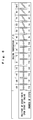
- step S2 the position of the choke valve 9(start opening degree or start opening angle) corresponding to the detected temperature is determined.
- the start opening degree is read out, for example, from a predetermined table as shown in Fig. 6.
- the position of the choke valve 9 is indicated by the number of steps to be supplied to the stepping motor 11. The detail of Fig. 6 is described later.
- step S3 for example using a predetermined table as shown in Fig. 7, the working time until release of choke corresponding to the engine temperature (basic choke release time) is determined.
- the detail of Fig. 7 is described later.
- step S4 first the stepping motor 11 is driven in order to initialize, and the stepping motor 11 is driven for rotating the choke valve 9 until start opening degree.
- a driving signal of a predetermined number of steps is supplied to the stepping motor 11 so as to move the choke valve 9 to the fully closed side or fully opened side.
- the choke valve 9 is fully closed or fully opened.
- the start opening degree of the choke valve 9 is determined on the basis of this fully closed or fully opened position.
- step S5 it is judged whether the choke valve 9 is opened to half or not. This is judged by the number of steps of the driving signal supplied to the stepping motor 11. If the choke valve 9 is opened to less than half, advancing to step S6, the engine speed is detected. The engine speed can be detected on the basis of the output period of the BTDC sensor 15, but the method of detection is not particularly specified.
- step S7 the motor driving condition until the choke valve 9 is opened to half is determined.
- the basic choke release time determined at step S3 (working time from start opening degree to half open) is corrected. In this correction, as the engine speed is higher, the basic choke release time is shortened, and as the engine speed is lower, the basic choke release time is extended.
- the number of steps of the driving signal supplied to the stepping motor 11 in every driving period (for example, 0.7 sec) is determined on the basis of this driving period and the basic choke release time extended or shortened corresponding to increase or decrease of engine speed.
- the number of steps of the driving signal supplied per driving period is increased, it is fast to move to the choke release side, whereas if the number of steps supplied per driving period is decreased, it is slow to move to the choke release side.
- step S7 the number of steps of the driving signal in every driving period to be supplied to the stepping motor 11 until the choke valve 9 is opened half from start opening degree is determined, and at step S8, the stepping motor 11 is driven in the determined motor driving condition (determined number of steps) .
- step S5 If it is judged at step S5 that the choke valve 9 is open to half, skipping to step S9, it is judged if the choke valve 9 is fully opened or not. Same as in judgement of half open, it is determined by the number of steps supplied to the stepping motor 11.
- step S10 If the choke valve 9 is not fully opened, going to step S10, the engine speed is detected.
- step S11 the motor driving condition until the choke valve 9 is opened fully is determined.
- step S11 same as at step S7, the basic choke release time by the engine speed (working time from half open to full open) is corrected, and the number of steps of the driving signal in every driving period on the stepping motor 11 is calculated.
- step S12 the stepping motor 11 is driven in the determined motor driving condition (determined number of the steps).
- Fig. 3 is a specific flowchart of initialization (step s4) of the stepping motor 11.
- step S41 the pulse rate of the stepping motor 11 is determined depending on the engine temperature.
- An example of setting table of pulse rate of the stepping motor 11 in relation to temperature is shown in Fig. 4.
- step S42 it is judged if the start opening degree determined at step S2 is less than the predicted value (for example, half open). If the start opening degree is less than half open, the process goes to step S43, and if the start opening degree is half open or more, the process goes to step S44.
- the predicted value for example, half open
- the stepping motor 11 is initialized at the fully closed side of the choke valve 9. That is, the choke valve 9 is turned to the fully closed side at the pulse rate determined at step S41.
- the stepping motor 11 is initialized at the fully opened side of the choke valve 9. That is, the choke valve 9 is turned to the fully opened side at the pulse rate determined at step S41.
- the choke valve 9 is driven to fully closed position, where the stepping motor 11 is initialized.
- the choke valve 9 is driven to fully opened position, where the stepping motor 11 is initialized.
- a stepping motor for example, when the pulse rate is large, the rotor rotation cannot follow up the excitation, possibly falling in out-of-tune status.
- the rotor in the steppingmotor controlled in open loop, the rotor does not rotate by a desired angle corresponding to the number of steps of the given driving signal. That is, when releasing the choke, although the driving signal by the number of steps corresponding to the fully opened position is given to the stepping motor 11, the choke valve 9 may not be fully opened due to out-of-tune or other trouble.
- Fig. 5 is a flowchart showing processing of essential parts of the choke controller for the fully opened feed control.
- step S20 it is judged whether or not during the fully opened feed period for supplying driving signal to the stepping motor 11 in fully opened feed control.
- the fully opened feed period can be judged, for example, by providing the choke controller 17 with 2-second timer means, and checking if the timer means expires or not. If it is the predetermined fully opened feed period, going to step S21, a command (fully opened command) for fully opened feed is issued to the stepping motor 11. That is, a preset number of driving signals for moving the choke valve 9 to the fully opened side are sent out to the stepping motor 11.
- the number of driving signals for fully opened feed is, for example, 5 steps.
- Fully opened feed may be executed at a specific timing after engine start, and it not limited to periodical timing.
- Fig. 6 shows the position or start opening degree of the choke valve 9 at various engine temperatures upon start of engine, expressed by the number of steps of the stepping motor 11.
- the stepping motor 11 is initialized at the fully closed side of the choke valve 9. Since, at the engine temperature of 60 °C or higher, the start opening degree is at opened side from the half open state, the stepping motor 11 is initialized at the fully opened side of the choke valve 9.
- Fig. 7 is an example showing choke release time corresponding to the engine temperature.
- This is an example of basic choke release time when the engine speed is controlled by an electronic governor to be at reference speed of 3300 rpm. Therefore, if the reference speed varies with fluctuations of the load connected to the generator 12, the basic choke release time (working time until half open, and working time from half open to full open) is corrected depending on the engine speed. That is, when the load increases and the engine speed changes somewhat higher than the reference speed, the choke release time is shortened, and when the load decreases and the engine speed changes somewhat lower than the reference speed, the choke release time is extended. Thus, the choke release time is corrected to be appropriate depending on the running condition of the generator 12, that is, the engine 1.
- the stepping motor is used as the driving source of the choke valve, but not limited to the stepping motor, for example, a servo motor may be similarly used.
- the engine temperature is represented by the temperature of the cylinder head 2a, but the engine temperature for choke valve control is not limited to the temperature at this position.
- a temperature sensor may be installed in an oil pan or water jacket for engine cooling water, and the temperature of lubricating oil or temperature of engine cooling watermay be detected, and used as engine temperature.
- any temperature information detected in engine case parts capable of representing the engine temperature may be employed in the choke valve control of the invention.
Landscapes
- Engineering & Computer Science (AREA)
- Chemical & Material Sciences (AREA)
- Combustion & Propulsion (AREA)
- Mechanical Engineering (AREA)
- General Engineering & Computer Science (AREA)
- Means For Warming Up And Starting Carburetors (AREA)
- Electrical Control Of Air Or Fuel Supplied To Internal-Combustion Engine (AREA)
- Control Of Stepping Motors (AREA)
- Control Of Throttle Valves Provided In The Intake System Or In The Exhaust System (AREA)
Applications Claiming Priority (2)
| Application Number | Priority Date | Filing Date | Title |
|---|---|---|---|
| JP2004078162 | 2004-03-18 | ||
| JP2004078162A JP4199688B2 (ja) | 2004-03-18 | 2004-03-18 | オートチョーク装置 |
Publications (3)
| Publication Number | Publication Date |
|---|---|
| EP1577532A2 true EP1577532A2 (de) | 2005-09-21 |
| EP1577532A3 EP1577532A3 (de) | 2013-07-03 |
| EP1577532B1 EP1577532B1 (de) | 2016-07-27 |
Family
ID=34836573
Family Applications (1)
| Application Number | Title | Priority Date | Filing Date |
|---|---|---|---|
| EP05005969.0A Ceased EP1577532B1 (de) | 2004-03-18 | 2005-03-18 | Kaltstartautomatik |
Country Status (4)
| Country | Link |
|---|---|
| US (1) | US7117834B2 (de) |
| EP (1) | EP1577532B1 (de) |
| JP (1) | JP4199688B2 (de) |
| CN (1) | CN100425815C (de) |
Cited By (2)
| Publication number | Priority date | Publication date | Assignee | Title |
|---|---|---|---|---|
| EP3404251A4 (de) * | 2016-01-15 | 2019-02-13 | Suzhou Cleva Precision Machinery & Technology Co., Ltd. | Tragbares benzin werkzeug und elektronisches zündsystem dafür |
| EP3404239A4 (de) * | 2016-01-15 | 2019-08-07 | Suzhou Cleva Precision Machinery & Technology Co., Ltd. | Gartenwerkzeug |
Families Citing this family (14)
| Publication number | Priority date | Publication date | Assignee | Title |
|---|---|---|---|---|
| US7171947B2 (en) * | 2005-05-27 | 2007-02-06 | Honda Motor Co., Ltd. | Electrically-actuated throttle device for general-purpose engine |
| JP2008255881A (ja) * | 2007-04-04 | 2008-10-23 | Kyoto Denkiki Kk | エンジン |
| US8219305B2 (en) | 2008-05-27 | 2012-07-10 | Briggs & Stratton Corporation | Engine with an automatic choke and method of operating an automatic choke for an engine |
| US7628387B1 (en) | 2008-07-03 | 2009-12-08 | Briggs And Stratton Corporation | Engine air/fuel mixing apparatus |
| CN104884776B (zh) | 2013-08-15 | 2018-09-25 | 科勒公司 | 用于电子地控制内燃机的燃料空气比的系统和方法 |
| JP6022074B2 (ja) * | 2013-10-10 | 2016-11-09 | 三菱電機株式会社 | 内燃機関の制御装置および制御方法 |
| US10054081B2 (en) | 2014-10-17 | 2018-08-21 | Kohler Co. | Automatic starting system |
| CN105673290B (zh) * | 2016-01-15 | 2018-11-09 | 苏州科瓴精密机械科技有限公司 | 便携式汽油工具 |
| US20190024611A1 (en) * | 2016-01-25 | 2019-01-24 | Husqvarna Ab | Internal combustion engine provided with a semi- automatic choke device |
| CN105626285B (zh) * | 2016-01-29 | 2019-01-25 | 深圳市力骏泰燃气动力科技有限公司 | 一种发动机混合气智能调节系统 |
| JP6946357B2 (ja) * | 2017-02-09 | 2021-10-06 | 株式会社Fuji | 部品実装機 |
| CN111042972A (zh) * | 2019-12-31 | 2020-04-21 | 重庆鑫源农机股份有限公司 | 一种发电机启动控制电路及发电机 |
| CN112096540B (zh) * | 2020-09-15 | 2022-09-13 | 重庆华世丹动力科技有限公司 | 发电机的发动机低温启动时风门控制方法 |
| CN113738538A (zh) * | 2021-07-26 | 2021-12-03 | 深圳拓邦股份有限公司 | 阻风门完全关闭和完全开启的判断方法、增程器和发动机 |
Citations (1)
| Publication number | Priority date | Publication date | Assignee | Title |
|---|---|---|---|---|
| JPH05280425A (ja) | 1992-03-31 | 1993-10-26 | Suzuki Motor Corp | オートチョーク装置 |
Family Cites Families (11)
| Publication number | Priority date | Publication date | Assignee | Title |
|---|---|---|---|---|
| IT1081383B (it) * | 1977-04-27 | 1985-05-21 | Magneti Marelli Spa | Apparecchiatura elettronica per il controllo dell'alimentazione di una miscela aria/benzina di un motore a combustione interna |
| DE2927881C2 (de) * | 1979-07-11 | 1984-06-28 | Bosch und Pierburg System oHG, 4040 Neuss | Verfahren und Vorrichtung zur Übergangsanreicherung bei Gemischbildnern |
| US4623322A (en) * | 1979-12-03 | 1986-11-18 | North American Philips Corporation | Mechanical drive with bi-directional override |
| US4321902A (en) * | 1980-04-11 | 1982-03-30 | General Motors Corporation | Engine control method |
| US4463723A (en) * | 1982-04-01 | 1984-08-07 | Acf Industries, Incorporated | Apparatus for controllably opening a carburetor choke valve |
| IT1157490B (it) * | 1982-12-20 | 1987-02-11 | Weber Spa | Carburatore per motori a combustione interna provvisto di organi ad azione elettronica atti a mantenere costante il minimo regime del motore ed a controllare la posizione della farfalla di avviamento durante la messa in efficienza del motore |
| JPS6291644A (ja) * | 1985-10-17 | 1987-04-27 | Toyota Motor Corp | スロツトルバルブの開閉制御装置 |
| JPH0629595B2 (ja) * | 1989-03-03 | 1994-04-20 | いすゞ自動車株式会社 | スロットル制御装置 |
| DE3924353A1 (de) * | 1989-07-22 | 1991-02-14 | Prufrex Elektro App | Steuerungssystem fuer den vergaser einer brennkraftmaschine |
| JP3546469B2 (ja) * | 1994-06-03 | 2004-07-28 | 三菱電機株式会社 | 流量弁制御装置 |
| JP2001329867A (ja) * | 2000-05-23 | 2001-11-30 | Mitsubishi Electric Corp | 吸入空気量制御装置 |
-
2004
- 2004-03-18 JP JP2004078162A patent/JP4199688B2/ja not_active Expired - Fee Related
-
2005
- 2005-03-16 US US11/080,434 patent/US7117834B2/en not_active Expired - Lifetime
- 2005-03-18 EP EP05005969.0A patent/EP1577532B1/de not_active Ceased
- 2005-03-18 CN CNB2005100557340A patent/CN100425815C/zh not_active Expired - Fee Related
Patent Citations (1)
| Publication number | Priority date | Publication date | Assignee | Title |
|---|---|---|---|---|
| JPH05280425A (ja) | 1992-03-31 | 1993-10-26 | Suzuki Motor Corp | オートチョーク装置 |
Cited By (2)
| Publication number | Priority date | Publication date | Assignee | Title |
|---|---|---|---|---|
| EP3404251A4 (de) * | 2016-01-15 | 2019-02-13 | Suzhou Cleva Precision Machinery & Technology Co., Ltd. | Tragbares benzin werkzeug und elektronisches zündsystem dafür |
| EP3404239A4 (de) * | 2016-01-15 | 2019-08-07 | Suzhou Cleva Precision Machinery & Technology Co., Ltd. | Gartenwerkzeug |
Also Published As
| Publication number | Publication date |
|---|---|
| JP2005264816A (ja) | 2005-09-29 |
| US7117834B2 (en) | 2006-10-10 |
| US20050205039A1 (en) | 2005-09-22 |
| EP1577532A3 (de) | 2013-07-03 |
| CN100425815C (zh) | 2008-10-15 |
| EP1577532B1 (de) | 2016-07-27 |
| JP4199688B2 (ja) | 2008-12-17 |
| CN1670354A (zh) | 2005-09-21 |
Similar Documents
| Publication | Publication Date | Title |
|---|---|---|
| EP1574700B1 (de) | Kaltstartautomatik | |
| EP1577532B1 (de) | Kaltstartautomatik | |
| US7284522B2 (en) | Automatic choke | |
| EP0623741B1 (de) | Drehmomentregelung für einen Gasturbinenstarter | |
| US6957636B2 (en) | Apparatus and method for preventing an overshoot in the rotation speed of an internal-combustion engine | |
| US5280772A (en) | Process for controlling the speed of an internal combustion engine after starting | |
| JP4199686B2 (ja) | オートチョーク装置 | |
| JP4148414B2 (ja) | オートチョーク装置 | |
| JP2005264817A (ja) | オートチョーク装置 | |
| JP4199689B2 (ja) | オートチョーク装置 | |
| JP4232968B2 (ja) | オートチョーク装置 | |
| JPS595855A (ja) | 内燃エンジンのアイドル回転数安定化装置 | |
| JPS63124834A (ja) | ガスエンジンの制御装置 | |
| JP2577727B2 (ja) | エンジンの始動装置 | |
| JPS6240548B2 (de) | ||
| JP2871365B2 (ja) | 内燃機関の制御装置 | |
| JPH04318239A (ja) | 内燃機関制御装置 | |
| JP2002276414A (ja) | オルタネータの発電制御装置 | |
| JPH03143300A (ja) | オルタネータ制御装置 | |
| WO2004013488A1 (ja) | オートチョーク制御装置 | |
| JPH03224819A (ja) | 車両用エアコンのコンプレッサ制御装置 | |
| JPH0550585B2 (de) | ||
| JP2003129885A (ja) | エンジンのアイドル回転数制御装置 |
Legal Events
| Date | Code | Title | Description |
|---|---|---|---|
| PUAI | Public reference made under article 153(3) epc to a published international application that has entered the european phase |
Free format text: ORIGINAL CODE: 0009012 |
|
| AK | Designated contracting states |
Kind code of ref document: A2 Designated state(s): AT BE BG CH CY CZ DE DK EE ES FI FR GB GR HU IE IS IT LI LT LU MC NL PL PT RO SE SI SK TR |
|
| AX | Request for extension of the european patent |
Extension state: AL BA HR LV MK YU |
|
| PUAL | Search report despatched |
Free format text: ORIGINAL CODE: 0009013 |
|
| AK | Designated contracting states |
Kind code of ref document: A3 Designated state(s): AT BE BG CH CY CZ DE DK EE ES FI FR GB GR HU IE IS IT LI LT LU MC NL PL PT RO SE SI SK TR |
|
| AX | Request for extension of the european patent |
Extension state: AL BA HR LV MK YU |
|
| RIC1 | Information provided on ipc code assigned before grant |
Ipc: F02D 41/00 20060101ALI20130528BHEP Ipc: F02D 41/06 20060101ALI20130528BHEP Ipc: F02M 1/08 20060101AFI20130528BHEP |
|
| 17P | Request for examination filed |
Effective date: 20130731 |
|
| RBV | Designated contracting states (corrected) |
Designated state(s): AT BE BG CH CY CZ DE DK EE ES FI FR GB GR HU IE IS IT LI LT LU MC NL PL PT RO SE SI SK TR |
|
| AKX | Designation fees paid |
Designated state(s): DE FR GB |
|
| 17Q | First examination report despatched |
Effective date: 20140509 |
|
| REG | Reference to a national code |
Ref country code: DE Ref legal event code: R079 Ref document number: 602005049806 Country of ref document: DE Free format text: PREVIOUS MAIN CLASS: F02M0001080000 Ipc: F02D0041060000 |
|
| GRAP | Despatch of communication of intention to grant a patent |
Free format text: ORIGINAL CODE: EPIDOSNIGR1 |
|
| RIC1 | Information provided on ipc code assigned before grant |
Ipc: F02D 41/06 20060101AFI20160113BHEP |
|
| INTG | Intention to grant announced |
Effective date: 20160209 |
|
| GRAS | Grant fee paid |
Free format text: ORIGINAL CODE: EPIDOSNIGR3 |
|
| GRAR | Information related to intention to grant a patent recorded |
Free format text: ORIGINAL CODE: EPIDOSNIGR71 |
|
| GRAA | (expected) grant |
Free format text: ORIGINAL CODE: 0009210 |
|
| RIN1 | Information on inventor provided before grant (corrected) |
Inventor name: KAMIMURA, KENJI Inventor name: NAKAMURA, MASASHI Inventor name: ASAI, KOUICHI |
|
| AK | Designated contracting states |
Kind code of ref document: B1 Designated state(s): DE FR GB |
|
| INTG | Intention to grant announced |
Effective date: 20160621 |
|
| REG | Reference to a national code |
Ref country code: GB Ref legal event code: FG4D |
|
| REG | Reference to a national code |
Ref country code: DE Ref legal event code: R096 Ref document number: 602005049806 Country of ref document: DE |
|
| REG | Reference to a national code |
Ref country code: FR Ref legal event code: PLFP Year of fee payment: 13 |
|
| REG | Reference to a national code |
Ref country code: DE Ref legal event code: R097 Ref document number: 602005049806 Country of ref document: DE |
|
| PLBE | No opposition filed within time limit |
Free format text: ORIGINAL CODE: 0009261 |
|
| STAA | Information on the status of an ep patent application or granted ep patent |
Free format text: STATUS: NO OPPOSITION FILED WITHIN TIME LIMIT |
|
| 26N | No opposition filed |
Effective date: 20170502 |
|
| REG | Reference to a national code |
Ref country code: FR Ref legal event code: PLFP Year of fee payment: 14 |
|
| PGFP | Annual fee paid to national office [announced via postgrant information from national office to epo] |
Ref country code: DE Payment date: 20190305 Year of fee payment: 15 Ref country code: GB Payment date: 20190313 Year of fee payment: 15 |
|
| PGFP | Annual fee paid to national office [announced via postgrant information from national office to epo] |
Ref country code: FR Payment date: 20190213 Year of fee payment: 15 |
|
| REG | Reference to a national code |
Ref country code: DE Ref legal event code: R119 Ref document number: 602005049806 Country of ref document: DE |
|
| PG25 | Lapsed in a contracting state [announced via postgrant information from national office to epo] |
Ref country code: DE Free format text: LAPSE BECAUSE OF NON-PAYMENT OF DUE FEES Effective date: 20201001 Ref country code: FR Free format text: LAPSE BECAUSE OF NON-PAYMENT OF DUE FEES Effective date: 20200331 |
|
| GBPC | Gb: european patent ceased through non-payment of renewal fee |
Effective date: 20200318 |
|
| PG25 | Lapsed in a contracting state [announced via postgrant information from national office to epo] |
Ref country code: GB Free format text: LAPSE BECAUSE OF NON-PAYMENT OF DUE FEES Effective date: 20200318 |