EP1577552A2 - Taumelscheibenkompressor mit festem Winkel - Google Patents
Taumelscheibenkompressor mit festem Winkel Download PDFInfo
- Publication number
- EP1577552A2 EP1577552A2 EP05005939A EP05005939A EP1577552A2 EP 1577552 A2 EP1577552 A2 EP 1577552A2 EP 05005939 A EP05005939 A EP 05005939A EP 05005939 A EP05005939 A EP 05005939A EP 1577552 A2 EP1577552 A2 EP 1577552A2
- Authority
- EP
- European Patent Office
- Prior art keywords
- swash plate
- bearing
- shaft
- compressor
- plate portion
- Prior art date
- Legal status (The legal status is an assumption and is not a legal conclusion. Google has not performed a legal analysis and makes no representation as to the accuracy of the status listed.)
- Withdrawn
Links
Images


Classifications
-
- F—MECHANICAL ENGINEERING; LIGHTING; HEATING; WEAPONS; BLASTING
- F42—AMMUNITION; BLASTING
- F42D—BLASTING
- F42D5/00—Safety arrangements
- F42D5/04—Rendering explosive charges harmless, e.g. destroying ammunition; Rendering detonation of explosive charges harmless
- F42D5/055—Silencing means for blasting operations
-
- F—MECHANICAL ENGINEERING; LIGHTING; HEATING; WEAPONS; BLASTING
- F04—POSITIVE - DISPLACEMENT MACHINES FOR LIQUIDS; PUMPS FOR LIQUIDS OR ELASTIC FLUIDS
- F04B—POSITIVE-DISPLACEMENT MACHINES FOR LIQUIDS; PUMPS
- F04B27/00—Multi-cylinder pumps specially adapted for elastic fluids and characterised by number or arrangement of cylinders
- F04B27/08—Multi-cylinder pumps specially adapted for elastic fluids and characterised by number or arrangement of cylinders having cylinders coaxial with, or parallel or inclined to, main shaft axis
- F04B27/10—Multi-cylinder pumps specially adapted for elastic fluids and characterised by number or arrangement of cylinders having cylinders coaxial with, or parallel or inclined to, main shaft axis having stationary cylinders
- F04B27/1036—Component parts, details, e.g. sealings, lubrication
- F04B27/1054—Actuating elements
- F04B27/1063—Actuating-element bearing means or driving-axis bearing means
-
- E—FIXED CONSTRUCTIONS
- E21—EARTH OR ROCK DRILLING; MINING
- E21D—SHAFTS; TUNNELS; GALLERIES; LARGE UNDERGROUND CHAMBERS
- E21D9/00—Tunnels or galleries, with or without linings; Methods or apparatus for making thereof; Layout of tunnels or galleries
- E21D9/006—Tunnels or galleries, with or without linings; Methods or apparatus for making thereof; Layout of tunnels or galleries by making use of blasting methods
Definitions
- the present invention relates to an apparatus for generating compressed fluid. More specifically, the invention relates to a swash plate compressor that maintains a fixed angle while minimizing the number of bearing assemblies required.
- Swash plate compressors are generally known in the art. These compressors typically employ a cylinder block with a plurality of piston channels mounted on a drive shaft. A plurality of pistons are slidably disposed in the piston channels and are coupled to a swash plate that is also mounted on the drive shaft. In accordance with the rotation of the drive shaft, the swash plate pivots, causing reciprocal motion of the pistons within the piston channels, thereby alternately creating suction and compression strokes.
- compressors employ a variety of mechanisms that utilize the rotational force of the drive shaft to make the swash plate pivot, such as an actuating assembly with a slanted surface underneath the swash plate, as disclosed in U.S. Patent No. 6,439,857 to Koelzer and assigned to the assignee of the present application, an assembly of rotating and non-rotating plates, as disclosed in U.S. Patent No. 5,626,463 to Kimura, and a rotatable cylinder block, as disclosed in U.S. Patent No. 5,394,698 to Takagi.
- the pistons reciprocate within the piston channels of the cylinder block, alternately drawing fluid to be compressed into the channels and subsequently compressing and discharging the fluid.
- the rotational force of the shaft is converted into axial motion of the pistons, enabling the pistons to alternately perform the functions of suction and compression, and thus, fluid is first drawn into a piston channel and is subsequently compressed and discharged from the piston channel.
- a swash plate compressor that is inexpensive to manufacture. What is further desired is a swash plate compressor that is easy to assemble. What is also desired is a swash plate compressor that minimizes the amount of bearings required.
- the invention comprises a compressor as defined in independent claim 1.
- the compressor included a housing, a shaft disposed in the housing, the shaft having a longitudinal axis, an inner swash plate portion attached to the shaft at a fixed angle relative to the longitudinal axis of the shaft, an outer swash plate portion coupled to the inner swash plate portion, and a bearing assembly by which the outer swash plate portion is coupled to the inner swash plate portion, wherein the bearing assembly is adapted to accommodate both the radial load and the axial load of the swash plate portions.
- the invention comprises a compressor including a housing, a shaft disposed in the housing, the shaft having a longitudinal axis, a swash plate coupled to the shaft at a fixed angle relative to the longitudinal axis of the shaft, and a bearing assembly by which the swash plate is coupled to the shaft, wherein the bearing assembly is adapted to accommodate both the radial load and the axial load of the swash plate.
- the invention comprises a compressor including a housing having at least one piston channel, a shaft disposed in the housing, a swash plate coupled to the shaft, at least one piston disposed in the at least one piston channel and movable therein, wherein the swash plate is coupled to the at least one piston and inclined at an angle relative to the direction of motion thereof, and a bearing assembly by which the swash plate is coupled to the shaft, such that the angle at which the swash plate is inclined relative to the direction of motion of the at least one piston remains fixed as the shaft rotates, wherein the bearing assembly is adapted to accommodate both the radial load and the axial load of the swash plate.
- the invention comprises a compressor including a housing, a shaft disposed in the housing, the shaft having a longitudinal axis, an inner swash plate portion attached to the shaft at a fixed angle relative to the longitudinal axis of the shaft, an outer swash plate portion coupled to the inner swash plate portion, and an angular contact bearing by which the outer swash plate portion is coupled to the inner swash plate portion.
- the invention comprises a compressor including a housing, a shaft disposed in the housing, the shaft having a longitudinal axis, a swash plate coupled to the shaft at a fixed angle relative to the longitudinal axis of the shaft, and an angular contact bearing by which the swash plate is coupled to the shaft.
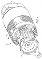
- Figure 1 is an isometric view of a swash plate compressor in accordance with the invention.
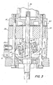
- Figure 2 is a cross-sectional side view of the compressor of Figure 1.
- Figure 3 is a cross-sectional side view of another embodiment of the compressor of Figure 1.
- Figure 4 is an isometric view of the swash plate assembly of the compressor of Figure 3.
- Figure 5 is another cut-away, cross-sectional side view of one embodiment of the shaft and swash plate of the compressor of Figure 1.
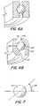
- Figure 6a is a partial cross-sectional, isometric view of a standard radial bearing.
- Figure 6b is a partial cross-sectional, isometric view of an angular contact bearing of the swash plate of the compressor of Figure 1.
- Figure 7 is an exposed side view of the ball bearing of Figure 6b.
- Figure 8 is a partial cross-sectional, isometric view of a tapered roller bearing used in some embodiments of the swash plate of the compressor of Figure 1.
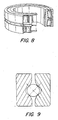
- Figure 9 is a cross-sectional side view of a four point contact bearing used in some embodiments of the swash plate of the compressor of Figure 1.
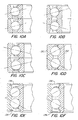
- Figure 10a is a cross-sectional side view of a tandem duplex-bearing used in some embodiments of the swash plate of the compressor of Figure 1.
- Figure 10b is a cross-sectional side view of a face-to-face duplex-bearing used in some embodiments of the swash plate of the compressor of Figure 1.
- Figure 10c is a cross-sectional side view of a back-to-back duplex-bearing used in some embodiments of the swash plate of the compressor of Figure 1.
- Figure 10d is a cross-sectional side view of a double row angular contact bearing used in some embodiments of the swash plate of the compressor of Figure 1.
- Figure 10e is a cross-sectional side view of a shielded type of the double row angular contact bearing of Figure 10d.
- Figure 10f is a cross-sectional side view of a sealed type of the double row angular contact bearing of Figure 10d.
- FIG. 1 The basic components of one embodiment of a swash plate compressor 10 in accordance with the invention are illustrated in Figure 1.
- the terms “top,” “bottom,” “above,” “below,” “over,” “under,” “on top,” “underneath,” “up,” “down,” “upper,” “lower,” “front,” “rear,” “forward” and “back” refer to the objects referenced when in the orientation illustrated in the drawings, which orientation is not necessary for achieving the objects of the invention.
- the compressor 10 includes a main body 12, a rear mounting cover 14, and a front mounting flange 16.
- the compressor 10 When in use, the compressor 10 is installed on a vehicle, such as an over-the-road truck, and generates compressed air for the vehicle's pressure system, which typically includes a tank (not shown) that supplies the compressed air to various accessories, such as, for example, the brake system.
- This production of the compressed air begins by receiving air, which may or may not be delivered from a turbocharger (not shown), in response to a reduction of the air pressure in the air system to or below a reference pressure.
- the fluid is air, in certain other embodiments, the fluid may comprises any of various gases, liquids, or mixtures thereof.
- the main body 12 includes a swash plate housing 20 defining a swash plate chamber 22 therein, and a stationary cylinder block 26 mounted to the housing 20.
- a drive shaft 40 extends through both the housing 20 and the cylinder block 26 and is rotatable therein.
- a swash plate 24 is disposed in the swash plate chamber 22 and mounted on the shaft 40.
- a plurality of pistons 30 are coupled to the swash plate 24, and the cylinder block 26 has a plurality of piston channels 32 that receive the pistons 30.
- the pistons 30 are reciprocally displaceable within the piston channels 32 in order to produce suction and compression strokes.
- Each piston 30 has a face 31 for contacting the air to be compressed. Accordingly, a compression chamber 34 is formed from the space in the piston channel 32 to which the piston face 31 is exposed.
- the compression chamber 34 which is in fluid communication with the air system, both receives air to be compressed and discharges air after compressing it. Accordingly, the air pressure in the compression chamber 34 corresponds to the air pressure in the air system, thereby ensuring a state of pressure equilibrium for the compressor 10, as is further explained below.
- the main body 12 of the compressor 10 further includes a compressor head 18 mounted adjacent to the cylinder block 26.
- the compressor head has an inlet channel 80 and an outlet channel 82 that are both in communication with the compression chambers 34.
- the compressor 10 is typically provided with a plurality of inlet and outlet valves 84, 85.
- valves 84, 85 which are often one-way reed or poppet valves, allow air to flow along a path from a high-pressure area to a low-pressure area, and are typically part of the compressor head 18, or are created using valve plates 86, 87 disposed between the compressor head 18 and the cylinder block 26.
- the compressor head 18 is provided with inlet and outlet ports, 90, 92, which are in fluid communication with the inlet and outlet channels 80, 82, respectively. Accordingly, air may be drawn in through the inlet port 90, into the inlet channel 80 and past the inlet valves 84, to the compression chambers 34 where it can be compressed. Similarly, once air is compressed and discharged from the compression chambers 34 through the outlet valves 85 and into the outlet channel 82, the air may be directed to the air system via the outlet port 92.
- the swash plate housing 20 is provided with an inlet port 91, thereby eliminating the need for an inlet port in the compressor head 18.
- air enters the swash plate chamber 22, cooling any bearings that may be found therein, and is communicated to the inlet channel 80 via a passageway 93.
- the swash plate 24 has an outer part 42 and inner part 44, wherein the outer part 42 is coupled to the inner part 44 via a bearing 46.
- the inner part 44 is mounted on the shaft 40 with a series of pins 48, such that the inner part 44 rotates with the shaft 40.
- the bearing 46 permits the outer part 42 of the swash plate 24 to be restrained as the inner part 44 rotates with the shaft 40.
- the outer part 42, the pistons 30, and the cylinder block 26 can all be non-rotating.
- the shaft 40 can continue to rotate even when the compressor 10 is not compressing air and the pistons 30 are idle.
- accessories coupled to the shaft 40 such as, for example, a fuel pump (not shown), continue to function.
- the swash plate 24 receives a radially extending stopper 49 that engages an axial groove of the housing 20, as shown in Figure 4.
- a gimbal arm 100 may be used to prevent the outer part 42 from rotating.
- the entire swash plate 24 remains inclined at a fixed angle 140 with respect to the longitudinal axis 39 of the shaft 40. Because the angle 140 is fixed, the inclined plane of the swash plate 24 rotates as the shaft 40 rotates. In this way, the rotational motion of swash plate 24 about the shaft 40 causes reciprocal displacement of the pistons 30 parallel to the axis 39 of the shaft 40.
- the pistons 30 are coupled to the swash plate 24 via a bearing.
- the outer part 42 of the swash plate 24 includes a plurality of ball links, each of which is comprised of a swash plate rod 52 and a ball element 54.
- the rods 52 which are typically spaced angularly equidistantly from one another along an outer periphery of the swash plate 24 and extend radially therefrom, are bolts having a thread on one end, which is screwed into the swash plate 24, and a nut 58 on the opposite end.
- the ball element 54 has a spherical outer surface for slidably engaging a flange 62 of a piston rod 60, which extends parallel to the rotating shaft 40. Accordingly, as the plane of inclination of the swash plate 24 rotates, and the position of the flange 62 changes relative to the plane perpendicular to the longitudinal axis 39 of the drive shaft 40, the cooperating surfaces of the ball element 54 and flange 62 slide relative to one another. Such relative displacement allows the piston rod 60 and ball element 54 to move axially together, while the ball element 54 rotates within the flange 62 in response to the rotating angle of inclination of the swash plate 24.
- the cooperating surfaces of the ball element 54 and flange 62 are depicted as annular, in certain embodiments, other shapes that move synchronously while being angularly displaced relative to one another may be used.
- the bearing by which the pistons 30 are coupled to the swash plate 24 may take other forms.
- outer swash plate part 42 is coupled to an inner swash plate part 44 via a bearing 46, and the inner swash plate part 44, in turn, is attached to the shaft 40 at an angle 140 relative to the longitudinal axis 39 of the shaft 40 that remains fixed. Accordingly, while the bearing 46 enables the outer part 42 to not rotate along with inner part 44 and shaft 40, the angle of inclination of the outer part 42 will rotate along with the angle of inclination of the inner part 44. In this way, the pistons 30 are displaced back and forth within the piston channels 32, thereby generating suction and compression strokes.
- the inner part 44 may be connected to the shaft 40 by a plurality of fasteners, such as pins 48, such that the inner part 44 remains at a fixed angle with respect to the longitudinal axis 39 of the shaft 40.
- the inner part 44 may be otherwise fixedly attached to the shaft 40, such as by welding the inner part 44 to the shaft 40, or by manufacturing the shaft 40 such that the inner part 44 is integrally formed therewith.
- the swash plate 24 may consist of a single, non-rotating part 45 that is directly coupled to a shaft 41 in such a way that it does not rotate with the shaft 41. This may be accomplished, for example, by providing a shaft 40 having a race 43 integrally formed therein, and by employing a bearing assembly such as bearing 46.
- the bearing 46 is a bearing adapted to accommodate not only the radial load resulting from the rotation of the shaft 40 relative to at least a portion of the swash plate 24, but also the axial load resulting from the sliding motion of the pistons 30 within the piston channels 32.
- this bearing comprises an angular contact bearing.
- Figure 6a which depicts a standard radial bearing
- Figure 6b which depicts an angular contact bearing
- an angular contact bearing unlike a standard radial bearing, allows the ball 110 to ride high on the edge of one of the raceways.
- this is accomplished by using raceways where one of the shoulders 112 is higher than the other shoulder 114, the higher shoulder 112 of the first raceway 120 being located at the opposite end from the higher shoulder 116 of the second raceway 122.
- the ball 110 instead of the ball 110 contacting the raceway 120 at an angle directly perpendicular to the longitudinal axis 39 of the shaft 40, the ball 110 will contact the raceway 120 at an angle 126, thereby enabling the bearing 46 to absorb more axial load.
- This angle of contact 126 is typically 15, 30, or 40 degrees from the normal angle of contact of a standard radial bearing, but does not necessarily have to be one of these specific angles.
- the bearing 46 may comprise any other bearing adapted to accommodate both the axial and radial loads of the compressor 10.
- the bearing 46 may comprise a tapered roller bearing.
- a four point contact bearing as shown in Figure 9, may be used.
- the bearing assembly contains multiple angular contact bearings side by side, commonly referred to as a duplex bearing.
- the bearing assembly may comprise a tandem duplex bearing, as shown in Figure 10a.
- two angular contact bearings that are facing the same direction are positioned adjacent each other in order to increase the level of axial load that the bearing assembly is able to accommodate.
- the bearing assembly includes a duplex bearing ⁇ such as those where axial loads exist in two directions ⁇ two angular contact bearings may be positioned adjacent each other such the bearings are facing in opposite directions. These arrangements serve to offset opposing axial loads, and would be useful, for example, in double-acting or two-step piston compressors.
- a face-to-face duplex bearing is employed, which allows for a larger misalignment angle.
- a back-to-back duplex bearing is employed, which provides greater rigidity.
- a double row angular contact bearing is employed, as shown in Figure 10d.
- two rows of angular contact bearings are arranged with shoulders positioned similar to that of a back-to-back duplex bearing, but the inner and outer rings 130, 132 are each a single piece that spans both rows of balls.
- the bearings are shielded, as illustrated in Figure 10e.
- shields 134 which, in some cases, are made of steel, are placed at either end of the bearing in order to keep foreign materials from entering the bearing.
- the bearings are sealed, as illustrated in Figure 10f.
- seals 136 are placed at either end of the bearing in order to both keep out foreign materials and keep in any grease that is used in the bearing.
Landscapes
- Engineering & Computer Science (AREA)
- General Engineering & Computer Science (AREA)
- Mechanical Engineering (AREA)
- Compressors, Vaccum Pumps And Other Relevant Systems (AREA)
- Rolling Contact Bearings (AREA)
- Rotary Pumps (AREA)
Applications Claiming Priority (2)
| Application Number | Priority Date | Filing Date | Title |
|---|---|---|---|
| US10/803,679 US20050207905A1 (en) | 2004-03-18 | 2004-03-18 | Fixed angle swash plate compressor |
| US803679 | 2004-03-18 |
Publications (2)
| Publication Number | Publication Date |
|---|---|
| EP1577552A2 true EP1577552A2 (de) | 2005-09-21 |
| EP1577552A3 EP1577552A3 (de) | 2006-12-13 |
Family
ID=34838924
Family Applications (1)
| Application Number | Title | Priority Date | Filing Date |
|---|---|---|---|
| EP05005939A Withdrawn EP1577552A3 (de) | 2004-03-18 | 2005-03-18 | Taumelscheibenkompressor mit festem Winkel |
Country Status (9)
| Country | Link |
|---|---|
| US (1) | US20050207905A1 (de) |
| EP (1) | EP1577552A3 (de) |
| JP (1) | JP2005264943A (de) |
| KR (1) | KR20060043772A (de) |
| CN (1) | CN1670370A (de) |
| AU (1) | AU2005201168A1 (de) |
| BR (1) | BRPI0500899A (de) |
| CA (1) | CA2501150A1 (de) |
| MX (1) | MXPA05002989A (de) |
Cited By (1)
| Publication number | Priority date | Publication date | Assignee | Title |
|---|---|---|---|---|
| WO2006066831A1 (de) * | 2004-12-20 | 2006-06-29 | Knorr-Bremse Systeme für Nutzfahrzeuge GmbH | Trockenlaufender taumelscheibenverdichter mit einer wälzgelagerten taumelscheibe |
Families Citing this family (8)
| Publication number | Priority date | Publication date | Assignee | Title |
|---|---|---|---|---|
| US20090232667A1 (en) * | 2006-07-12 | 2009-09-17 | Hugelman Rodney D | Axial compressor |
| CN101776055B (zh) * | 2009-01-13 | 2012-05-23 | 刘大磊 | 一种摆筒式容积泵 |
| CN102116290B (zh) * | 2010-11-03 | 2013-02-13 | 刘大磊 | 一种采用十字轴关节轴承的摆筒式容积泵 |
| US10309380B2 (en) | 2011-11-16 | 2019-06-04 | Ocean Pacific Technologies | Rotary axial piston pump |
| DE102014221778A1 (de) * | 2014-10-27 | 2016-04-28 | Robert Bosch Gmbh | Übertragungsmodul |
| US10094364B2 (en) | 2015-03-24 | 2018-10-09 | Ocean Pacific Technologies | Banded ceramic valve and/or port plate |
| KR102342345B1 (ko) * | 2017-04-05 | 2021-12-23 | 현대자동차주식회사 | 공조 장치, 상기 공조 장치를 포함하는 차량 및 공조 장치의 제어 방법 |
| DE102024002998A1 (de) * | 2024-09-18 | 2026-03-19 | Sks Gmbh | Verdichter |
Family Cites Families (14)
| Publication number | Priority date | Publication date | Assignee | Title |
|---|---|---|---|---|
| GB484114A (en) * | 1936-11-02 | 1938-05-02 | Dewandre Co Ltd C | Improvements in reciprocating pumps of the wobbler type |
| GB515635A (en) * | 1938-06-08 | 1939-12-11 | Frederick Henry Carey | Improvements in or relating to hydraulic reciprocating pumps and motors |
| GB781635A (en) * | 1955-03-04 | 1957-08-21 | Specialties Dev Corp | Piston driving mechanism for compressors |
| FR1195324A (fr) * | 1957-12-17 | 1959-11-17 | Perfectionnements aux compresseurs à pistons et spécialement aux compresseurs frigorifiques | |
| IT7922779V0 (it) * | 1978-11-11 | 1979-10-08 | Skf Kugellagerfabriken Gmbh | Cuscinetto a rotolamento. |
| JP2644412B2 (ja) * | 1992-03-26 | 1997-08-25 | 川崎重工業株式会社 | 油圧変速機 |
| JP3080278B2 (ja) * | 1992-10-05 | 2000-08-21 | 株式会社豊田自動織機製作所 | 往復動型圧縮機 |
| JP3031154B2 (ja) * | 1994-02-28 | 2000-04-10 | 株式会社日立製作所 | 等速継手 |
| CH691272A5 (de) * | 1995-07-05 | 2001-06-15 | Daimler Benz Ag | Hubkolbenmaschine mit Taumelscheibengetriebe. |
| JPH10159723A (ja) * | 1996-11-26 | 1998-06-16 | Nippon Soken Inc | 斜板型圧縮機 |
| IT1298458B1 (it) * | 1997-03-03 | 2000-01-10 | Luk Fahrzeug Hydraulik | Compressore per un impianto di climatizzazione di un autoveicolo |
| JP2001200784A (ja) * | 2000-01-19 | 2001-07-27 | Toyota Autom Loom Works Ltd | 斜板式圧縮機 |
| JP2002021717A (ja) * | 2000-07-04 | 2002-01-23 | Toyota Industries Corp | 片頭ピストン型圧縮機 |
| US6439857B1 (en) * | 2001-03-12 | 2002-08-27 | Haldex Brake Corporation | Axial piston compressor |
-
2004
- 2004-03-18 US US10/803,679 patent/US20050207905A1/en not_active Abandoned
-
2005
- 2005-03-17 KR KR1020050022338A patent/KR20060043772A/ko not_active Ceased
- 2005-03-17 MX MXPA05002989A patent/MXPA05002989A/es not_active Application Discontinuation
- 2005-03-17 AU AU2005201168A patent/AU2005201168A1/en not_active Abandoned
- 2005-03-17 JP JP2005077410A patent/JP2005264943A/ja active Pending
- 2005-03-17 CA CA002501150A patent/CA2501150A1/en not_active Abandoned
- 2005-03-18 CN CNA2005100656276A patent/CN1670370A/zh active Pending
- 2005-03-18 EP EP05005939A patent/EP1577552A3/de not_active Withdrawn
- 2005-03-18 BR BR0500899-9A patent/BRPI0500899A/pt not_active IP Right Cessation
Cited By (1)
| Publication number | Priority date | Publication date | Assignee | Title |
|---|---|---|---|---|
| WO2006066831A1 (de) * | 2004-12-20 | 2006-06-29 | Knorr-Bremse Systeme für Nutzfahrzeuge GmbH | Trockenlaufender taumelscheibenverdichter mit einer wälzgelagerten taumelscheibe |
Also Published As
| Publication number | Publication date |
|---|---|
| KR20060043772A (ko) | 2006-05-15 |
| MXPA05002989A (es) | 2005-09-21 |
| US20050207905A1 (en) | 2005-09-22 |
| JP2005264943A (ja) | 2005-09-29 |
| CA2501150A1 (en) | 2005-09-18 |
| AU2005201168A1 (en) | 2005-10-06 |
| EP1577552A3 (de) | 2006-12-13 |
| BRPI0500899A (pt) | 2005-11-01 |
| CN1670370A (zh) | 2005-09-21 |
Similar Documents
| Publication | Publication Date | Title |
|---|---|---|
| EP1553316B1 (de) | Doppelreihiges kugellager für scheibenträger | |
| EP1577552A2 (de) | Taumelscheibenkompressor mit festem Winkel | |
| EP0554791B1 (de) | Taumelscheiben-Kältemittelverdichter | |
| US7153105B2 (en) | Compressor with swash plate housing inlet port | |
| US5131319A (en) | Wobble plate type refrigerant compressor having a ball-and-socket joint lubricating mechanism | |
| US7318709B2 (en) | Pump valve assembly | |
| US6883416B2 (en) | Swash plate containment assembly | |
| US6393964B1 (en) | Compressor having piston rotation restricting structure with lubricating inclined guide surface | |
| US6019027A (en) | Refrigerant compressor | |
| US20050061143A1 (en) | Modular swash plate compressor | |
| JP4439434B2 (ja) | 等速ジョイント及びそれを用いた揺動斜板型圧縮機 | |
| US6098519A (en) | Fuel pump | |
| US6361286B1 (en) | Fuel pump | |
| JP2001032768A (ja) | 可変容量型斜板式圧縮機 | |
| JP2644746B2 (ja) | 可変容量斜板式圧縮機 | |
| JP2002054529A (ja) | 燃料ポンプ | |
| JP2007198484A (ja) | 等速ジョイント及びそれを用いた揺動斜板型圧縮機 |
Legal Events
| Date | Code | Title | Description |
|---|---|---|---|
| PUAI | Public reference made under article 153(3) epc to a published international application that has entered the european phase |
Free format text: ORIGINAL CODE: 0009012 |
|
| 17P | Request for examination filed |
Effective date: 20050326 |
|
| AK | Designated contracting states |
Kind code of ref document: A2 Designated state(s): AT BE BG CH CY CZ DE DK EE ES FI FR GB GR HU IE IS IT LI LT LU MC NL PL PT RO SE SI SK TR |
|
| AX | Request for extension of the european patent |
Extension state: AL BA HR LV MK YU |
|
| PUAL | Search report despatched |
Free format text: ORIGINAL CODE: 0009013 |
|
| AK | Designated contracting states |
Kind code of ref document: A3 Designated state(s): AT BE BG CH CY CZ DE DK EE ES FI FR GB GR HU IE IS IT LI LT LU MC NL PL PT RO SE SI SK TR |
|
| AX | Request for extension of the european patent |
Extension state: AL BA HR LV MK YU |
|
| AKX | Designation fees paid |
Designated state(s): DE FR GB IT PL SE |
|
| 17Q | First examination report despatched |
Effective date: 20071005 |
|
| STAA | Information on the status of an ep patent application or granted ep patent |
Free format text: STATUS: THE APPLICATION IS DEEMED TO BE WITHDRAWN |
|
| 18D | Application deemed to be withdrawn |
Effective date: 20091001 |