EP1577599A2 - Appareil pour contenir un fluide et procédé - Google Patents
Appareil pour contenir un fluide et procédé Download PDFInfo
- Publication number
- EP1577599A2 EP1577599A2 EP05251528A EP05251528A EP1577599A2 EP 1577599 A2 EP1577599 A2 EP 1577599A2 EP 05251528 A EP05251528 A EP 05251528A EP 05251528 A EP05251528 A EP 05251528A EP 1577599 A2 EP1577599 A2 EP 1577599A2
- Authority
- EP
- European Patent Office
- Prior art keywords
- fluid
- level
- vessel
- controller
- tank
- Prior art date
- Legal status (The legal status is an assumption and is not a legal conclusion. Google has not performed a legal analysis and makes no representation as to the accuracy of the status listed.)
- Withdrawn
Links
- 239000012530 fluid Substances 0.000 title claims abstract description 96
- 238000000034 method Methods 0.000 title claims description 10
- 239000003570 air Substances 0.000 claims description 7
- 239000012080 ambient air Substances 0.000 claims description 5
- 238000012544 monitoring process Methods 0.000 claims description 2
- 230000011664 signaling Effects 0.000 claims description 2
- 230000001419 dependent effect Effects 0.000 claims 1
- 238000005553 drilling Methods 0.000 abstract description 36
- 239000002002 slurry Substances 0.000 abstract description 5
- 239000000203 mixture Substances 0.000 abstract 1
- 239000007789 gas Substances 0.000 description 19
- 239000004020 conductor Substances 0.000 description 11
- 238000004891 communication Methods 0.000 description 4
- 238000003756 stirring Methods 0.000 description 4
- 239000002699 waste material Substances 0.000 description 4
- 238000013019 agitation Methods 0.000 description 3
- 239000007788 liquid Substances 0.000 description 3
- IJGRMHOSHXDMSA-UHFFFAOYSA-N Atomic nitrogen Chemical compound N#N IJGRMHOSHXDMSA-UHFFFAOYSA-N 0.000 description 2
- 238000004140 cleaning Methods 0.000 description 2
- 238000005520 cutting process Methods 0.000 description 2
- 239000000835 fiber Substances 0.000 description 2
- 230000035515 penetration Effects 0.000 description 2
- 239000007787 solid Substances 0.000 description 2
- 229910000831 Steel Inorganic materials 0.000 description 1
- 239000000654 additive Substances 0.000 description 1
- 230000015572 biosynthetic process Effects 0.000 description 1
- 238000010586 diagram Methods 0.000 description 1
- 231100001261 hazardous Toxicity 0.000 description 1
- 230000002706 hydrostatic effect Effects 0.000 description 1
- 238000012423 maintenance Methods 0.000 description 1
- 238000012986 modification Methods 0.000 description 1
- 230000004048 modification Effects 0.000 description 1
- 229910052757 nitrogen Inorganic materials 0.000 description 1
- 230000000630 rising effect Effects 0.000 description 1
- 239000010959 steel Substances 0.000 description 1
Images

Classifications
-
- B—PERFORMING OPERATIONS; TRANSPORTING
- B01—PHYSICAL OR CHEMICAL PROCESSES OR APPARATUS IN GENERAL
- B01F—MIXING, e.g. DISSOLVING, EMULSIFYING OR DISPERSING
- B01F35/00—Accessories for mixers; Auxiliary operations or auxiliary devices; Parts or details of general application
- B01F35/60—Safety arrangements
-
- B—PERFORMING OPERATIONS; TRANSPORTING
- B01—PHYSICAL OR CHEMICAL PROCESSES OR APPARATUS IN GENERAL
- B01F—MIXING, e.g. DISSOLVING, EMULSIFYING OR DISPERSING
- B01F27/00—Mixers with rotary stirring devices in fixed receptacles; Kneaders
- B01F27/80—Mixers with rotary stirring devices in fixed receptacles; Kneaders with stirrers rotating about a substantially vertical axis
- B01F27/90—Mixers with rotary stirring devices in fixed receptacles; Kneaders with stirrers rotating about a substantially vertical axis with paddles or arms
-
- B—PERFORMING OPERATIONS; TRANSPORTING
- B01—PHYSICAL OR CHEMICAL PROCESSES OR APPARATUS IN GENERAL
- B01F—MIXING, e.g. DISSOLVING, EMULSIFYING OR DISPERSING
- B01F35/00—Accessories for mixers; Auxiliary operations or auxiliary devices; Parts or details of general application
- B01F35/20—Measuring; Control or regulation
-
- B—PERFORMING OPERATIONS; TRANSPORTING
- B01—PHYSICAL OR CHEMICAL PROCESSES OR APPARATUS IN GENERAL
- B01F—MIXING, e.g. DISSOLVING, EMULSIFYING OR DISPERSING
- B01F35/00—Accessories for mixers; Auxiliary operations or auxiliary devices; Parts or details of general application
- B01F35/20—Measuring; Control or regulation
- B01F35/21—Measuring
- B01F35/211—Measuring of the operational parameters
- B01F35/2112—Level of material in a container or the position or shape of the upper surface of the material
-
- B—PERFORMING OPERATIONS; TRANSPORTING
- B01—PHYSICAL OR CHEMICAL PROCESSES OR APPARATUS IN GENERAL
- B01F—MIXING, e.g. DISSOLVING, EMULSIFYING OR DISPERSING
- B01F35/00—Accessories for mixers; Auxiliary operations or auxiliary devices; Parts or details of general application
- B01F35/20—Measuring; Control or regulation
- B01F35/22—Control or regulation
- B01F35/221—Control or regulation of operational parameters, e.g. level of material in the mixer, temperature or pressure
- B01F35/2214—Speed during the operation
- B01F35/22142—Speed of the mixing device during the operation
-
- B—PERFORMING OPERATIONS; TRANSPORTING
- B01—PHYSICAL OR CHEMICAL PROCESSES OR APPARATUS IN GENERAL
- B01F—MIXING, e.g. DISSOLVING, EMULSIFYING OR DISPERSING
- B01F35/00—Accessories for mixers; Auxiliary operations or auxiliary devices; Parts or details of general application
- B01F35/40—Mounting or supporting mixing devices or receptacles; Clamping or holding arrangements therefor
- B01F35/41—Mounting or supporting stirrer shafts or stirrer units on receptacles
- B01F35/411—Mounting or supporting stirrer shafts or stirrer units on receptacles by supporting only one extremity of the shaft
- B01F35/4111—Mounting or supporting stirrer shafts or stirrer units on receptacles by supporting only one extremity of the shaft at the top of the receptacle
Definitions
- the present invention relates to apparatus and method for containing a fluid.
- the present invention generally relates to the field of liquid and slurry agitation, and more specifically to the agitation of drilling fluid stored in tanks and as employed in the drilling industry, to apparatus for retaining a fluid level in a vessel below a predetermined level and to a method of agitating a fluid in a tank with a rotatable agitator.
- a key component or system that is employed in the drilling of oil and gas wells is the mud system, which circulates drilling fluid (mud) through the wellbore.
- the circulation system is also used to maintain the density of the drilling fluid by removing drilled cuttings from the fluid, and adding other solids to the fluid as may be desired.
- the density of the drilling fluid is critical to hole cleaning, rate of penetration, and pressure control in the well. Hole cleaning and rate of penetration are important factors in the efficiency of the drilling process, while pressure control is critical to drilling a well safely.
- drilling fluid is pumped by high-pressure pumps through the drill string and into the wellbore.
- the fluid exits the drill string at the bit and returns to the surface through the annulus between the drill string and the wellbore, carrying cuttings from the hole to the surface.
- the hydrostatic pressure from the column of drilling fluid prevents fluids from the surrounding earthen formation from entering the wellbore and potentially causing well blow out.
- the drilling fluid is then processed, in order to maintain the desired density, before it is pumped back through the drill string into the hole.
- the drilling fluid including a reserve volume, is typically stored in mud tanks at the surface before being recirculated through the well.
- the mud tanks are typically fabricated of steel and have a top or ceiling that serves as a deck upon which equipment is placed and personnel can walk and perform various duties.
- the mud tanks may have agitators or stirrers provided to keep the fluid circulating within the tank in order to minimise settling of the solids and other additives that are used to control the density and viscosity of the liquid slurry.
- the conventional agitator has a motor that drives a shaft and an impeller.
- the motor is normally placed on the top surface of the deck with the shaft and impeller extending down into the drilling mud.
- This conventional placement of the agitator motor, bearing and associated components on the deck of mud tanks presents operational difficulties and drawbacks. For example, space on the deck is limited during drilling operations. By positioning the agitator motor and related components on the top surface of the deck, the available space for other equipment and operating space for rig personnel is reduced. Deck-mounted equipment also presents trip hazards to personnel working or walking on the deck.
- Submerged agitators have been used in the past to increase the available space on the top of the mud tank.
- the submerged agitators are submerged in the drilling mud and are typically secured to a side wall of the mud tank.
- Drawbacks of using submerged agitators include difficulties in removal of the agitator from the mud tank, such as when servicing is required. Further drawbacks include the typically high initial expense of the submerged agitator.
- the submerged agitator may not properly stir the drilling mud because of the horizontal motion of its impellers in relation to the mud tank.
- the impeller speed of the submerged agitator is generally not adjusted depending on the mud level in the tank, which can result in a reduced life for the agitator motor if it must consistently operate at a high speed even at low mud levels, for example.
- an apparatus comprising: a tank for containing a fluid; a vessel within said tank, said vessel including a fluid-free compartment that is arranged to be free of said fluid in use; a motor housed in said fluid-free compartment; and, a shaft connected to said motor and extending from said fluid-free compartment and into a said fluid.
- an apparatus comprising: an enclosure for containing fluid that extends to a first fluid level within said enclosure; a top on said enclosure and a vessel attached to said top for extending into a said fluid, said vessel including a lower end having an opening arranged to allow a said fluid to extend into said vessel to a second fluid level, said second level being below said first level; a pressurised compartment within said vessel extending between said second fluid level and said enclosure top; a motor in said pressurised compartment; a shaft connected to said motor and extending from said vessel into a said fluid; an agitator connected to said shaft and disposed in said fluid beneath said second fluid level; a level detector in said vessel electrically coupled to a controller that is disposed outside of said enclosure; a source of compressed gas located outside said enclosure and coupled electrically to said controller; and, a conduit extending between said compressed gas source and said pressurised compartment; wherein said level detector, controller and compressed gas source are electrically coupled so that a signal generated by said level detector
- an apparatus for retaining a fluid level in a vessel below a predetermined level comprising: a vessel having an opening at a first end thereof; fluid surrounding said vessel and entering into said opening to a first fluid level; a pressurised region in said vessel above said first fluid level; and, control apparatus to keep said fluid in said vessel below the predetermined level, said control apparatus comprising: a controller; a compressor adapted to supply pressurised gas to said pressurised region upon receipt of a control signal from said controller; and, a first level detector in said vessel adapted to send a signal to said controller when said fluid level in said vessel rises to said first predetermined level; said compressor and said first level detector being electrically coupled to said controller.
- a method of agitating a fluid in a tank with a rotatable agitator comprising: monitoring the level of the fluid in the tank; sensing when the fluid level in the tank has dropped below a predetermined level; signalling a controller that the fluid level is below the predetermined minimum level; and, slowing the rotation of the agitator.
- a preferred embodiment may include an agitator apparatus for agitating a fluid or slurry contained within a tank or other enclosure.
- a vessel or chamber is disposed in the tank and includes a fluid-free compartment housing a motor.
- a shaft is connected to the motor and extends from the fluid-free compartment into the fluid. Blades and/or impellers are attached to the shaft at a position outside of the vessel for agitating the fluid in the tank.
- the fluid-free compartment may be pressurised to maintain the fluid level in the vessel below the motor. This enables a non-submersible and thus less costly motor to be employed.
- a hatch or other accessway may be provided in the enclosure to allow access into the fluid-free compartment for servicing the agitator motor and related components.
- the apparatus includes a controller and a level detector in the vessel for sensing the fluid level and sending a signal to the controller when the fluid level in the vessel rises to a predetermined level.
- the controller is electrically coupled to a compressed gas source and causes the source of compressed gas to communicate gas into the fluid-free compartment to maintain the fluid level below the predetermined level and thus below the motor.
- the apparatus further includes a pressure relief valve coupled electrically to the controller and adapted to open to cause gas to escape from the fluid-free compartment upon receipt of a control signal from the controller.
- the apparatus may include a second level detector in the vessel adapted to sense when the fluid in the vessel reaches a second predetermined level that is below the first predetermined level.
- the second or "low” level detector is also electrically coupled to the controller and, in this preferred embodiment, the controller actuates the pressure relief valve when the second level detector has detected that the fluid level in the vessel has reached the second predetermined or "low” level.
- the second level detector when the fluid level in the enclosure reaches the second predetermined or "low" level, as sensed by the second level detector, the second level detector signals the controller and the controller slows the speed of the motor and thus the speed of agitation in the enclosure or tank.
- the vessel is sealed and is pressurised to a pressure exceeding the ambient air pressure.
- the pressurised gas in the vessel maintains the fluid level in the vessel below the first predetermined level, and thus below the motor, and thereby maintains the compartment in a fluid-free and dry condition.
- the agitator motor may be an electric or hydraulic motor. It is believed that slowing the speed of the motor and agitator shaft and blades upon sensing of a low level condition has the advantage of increasing the life of the agitator as compared to similar agitators which continue to operate at relatively high speeds even when the fluid level in the enclosure has dropped significantly.
- agitator motor in the fluid-free compartment inside the enclosure, as opposed to conventional apparatus where the motor is placed on top of the enclosure, provides a valuable savings in working space for personnel, reduces trip hazards for personnel, and provides or frees space for other required equipment.
- the preferred embodiments provide an agitator that provides greater space on the top or deck of the mud tank; an agitator mounted below the deck of the mud tank that is more easily removed from the mud tank for service; a more effective way of stirring the drilling mud with an agitator mounted below the deck of the mud tank; and extended life of the agitator motor.
- Couple or “couples” or “coupled” are intended to mean either a direct or an indirect connection or link between devices that communicate with one another. Thus, for example, if a first device “couples” to a second device, that connection may be through a direct connection, or through an indirect connection via intermediate devices and connections.
- electrically coupled or “coupled electrically” mean that the components are coupled for communications by wire conductors, or fibre optic means, or may be connected by radio signals, or other communication means.
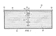
- FIG. 1 there is shown a schematic representation of a fluid-containing tank which, in this embodiment, constitutes mud tank 25 containing drilling mud 24.
- Mud tank 25 includes vessel 10 housing agitator apparatus 5.
- Vessel 10 includes fluid-free compartment 16.
- Agitator apparatus 5 includes agitator motor 37, supported on platform 15 within compartment 16, and agitator 20 extending downwardly from compartment 16 to agitate drilling mud 24.
- agitator 20 extends downward from compartment 16 and into the body of drilling mud 24 contained in mud tank 25.
- Tank 25 includes bottom 22, sides 23 and top 30. As conventional, bottom 22 and four sides 23 (two shown in Figure 1) are welded together to form a fluid-tight enclosure or tank. Top 30 may likewise be welded or otherwise suitably attached to sides 23.
- Vessel 10 attached to top 30 and extending downwardly into the drilling mud 24 is vessel 10.
- Vessel 10 includes side walls 11 and a support or platform 15 attached to and extending between walls 11.
- Vessel 10 is bolted or otherwise attached to tank top 30.
- vessel 10 and platform 15 may be supported by a frame (not shown) attached to tank top 30 so as to simplify assembly and service of the system.
- a gasket or other suitable seal (not shown) is disposed between vessel 10 and top 30 to allow compartment 16 to be pressurised.
- Vessel 10 includes lowermost end 13 that includes opening 34 allowing the drilling mud in tank 25 to communicate into vessel 10.
- the level of drilling mud within vessel 10 is controlled, such that the level remains beneath platform 15.
- Vessel 10 may be cylindrical, rectangular, or any other suitable shape.
- Platform 15 may be sized and shaped to match the cross-sectional shape of vessel 10, or may simply comprise, for example, transverse or cantilevered beams or other members that extend across vessel 10. In this embodiment, platform 15 is attached to sides 11 and also attached to braces 14 that extend from walls 11. Platform 15 further includes an aperture 60 for receiving agitator shaft 40.
- agitator apparatus 5 generally includes agitator motor 37 and agitator 20.
- Agitator 20 includes impeller 45 and extends between bearing 35 in vessel 10 and bearing support 42 disposed on the bottom 22 of the mud tank 25.
- Motor 37 and bearing 35 are mounted within fluid-free compartment 16 and supported by platform 15. In this embodiment, it is preferred that motor 37 be a hydraulic motor, although other types of driving apparatus may be employed, such as an electric motor. Bearing 35 helps support the weight of shaft 40 and impeller 45. Shaft 40 extends from bearing 35 through platform aperture 60 to drive and thereby rotate impeller 45. Motor 37 and bearing 35 are mechanically coupled in a conventional manner. Motor 37 may drive shaft 40 through a gearbox (not shown for clarity). Impeller 45 includes a plurality of blades or paddles 46 (four shown in this embodiment).
- Top 30 of tank 25 includes an accessway into vessel 10 which, in this embodiment, comprises hatch 38 that is removably attached to tank top 30. Hatch 38 and the accessway that it covers are sized so as to allow access into compartment 16 to allow removal of motor 37 and bearing 35 as repair or maintenance so requires. A gasket (not shown) or another seal is disposed between hatch 38 and tank top 30 to enable compartment 16 to be pressurised and sealed. The weight of the drilling mud 24 seals compartment 16 at opening 34.
- the upper surface of tank top 30 forms deck 39 that is used as a walkway by operating personnel and as a surface for supporting various equipment utilised in the operation and control of agitator apparatus 5. More specifically, in this particular embodiment, supported atop deck 39 is controller 75, compressor 80 and pressure-relief valve 85. Controller 75 preferably is a computer or programmable controller. Compressor 80 is a conventional gas compressor that is adapted to pressurise compartment 16 in vessel 10 by means of the interconnecting conduit 82. As shown in Figure 2, the lowermost end of conduit 82 extends to and opens into compartment 16 above opening 34.
- Level detectors 65,70 are electrically coupled to controller 75 via conductors 90, it being understood that each conductor 90 shown in Figure 2 may represent a pair of wires, a control cable, multiple conductors or other means for conducting electrical signals.
- Controller 75 is also electrically coupled to compressor 80 via conductor 91 so as to turn on and off the compressor when required, as described below.
- Conductor 92 electrically couples pressure-relief valve 85 with controller 75 such that controller 75 may cause pressure-relief valve 85 to open and release pressure within compartment 16, or close so as to maintain a desired pressure within the compartment 16.
- a hydraulic control module 36 for actuating hydraulic motor 37 is electrically coupled to controller 75 via conductor 93 such that, upon receipt of the appropriate electrical signal from controller 75, the hydraulic control module 36 will actuate to cause operation of hydraulic motor 37 by communicating pressurised fluid to motor 37 via hydraulic lines 33.
- Conductors 91,92,93 shown in Figure 2 may be multiple conductor cables, wire pairs, or other suitable electrical conductors.
- controller 75 actuates compressor 80 to pressurise the interior volume 32 of compartment 16 and to maintain the compartment mud level 50 at a level that is beneath platform 15. Due to this pressurization, compartment mud level 50 is thus well below the tank mud level 55 to which the drilling mud extends elsewhere in mud tank 25. Accordingly, compartment 16 is dry or fluid-free such that a conventional motor (as opposed to a more expensive submersible motor) may be employed in vessel 10 to actuate the agitator 20 within the tank 25.
- Level detectors 65,70 in conjunction with controller 75 operate to control mud level 50 within vessel 10 within predetermined limits. Should the level 50 within vessel 10 reach maximum level detector 70, the detector transmits a control signal to controller 75 via conductors 90.
- controller 75 Upon receipt of such signal, controller 75 actuates compressor 80 to increase the gas pressure within vessel 10 to drive the mud level 50 down below level detector 70. Similarly, should the level 50 within vessel 10 reach a predetermined minimum level, a control signal from level detector 65 to controller 75 signals controller 75 to cause pressure-relief valve 85 to open and thereby release pressure from within compartment 16 to allow the fluid level 50 to rise.
- Valve 85 can comprise any known valve suitable for releasing pressure. In alternative embodiments, more than one valve 85 can be used to release pressure from compartment 16.
- the present invention is not limited to securing vessel 10 to tank ceiling 30 but includes alternative embodiments comprising securing vessel 10 to any surface in mud tank 25, such as side walls 23.
- more than one compressor 80 may be used to supply gas to compartment 16.
- the gas can include atmospheric air, stored air, processed air, air that has been purified of flammable or hazardous gases and vapours, and the like.
- the present invention is not limited to supplying air to vessel 10 but may include supplying nitrogen or other gas suitable for use in drilling mud operations. Additionally, other sources for supplying compressed gas can be employed in place of the compressor 80.
- compartment 16 With compartment 16 sealed, pressure within the compartment prevents the drilling mud 24 from rising up and enveloping motor 37. As shown on Figure 2, the drilling mud level 50 in compartment 16 is lower than or beneath the drilling mud level 55 in mud tank 25.
- the rotational speed of agitator 20 may be adjusted depending on the level 55 of drilling mud in mud tank 25. More specifically, when the drilling mud level 50 drops below minimum level detector 65 in vessel 10, compressor 80 is shut off as previously described. Controller 75 will record that compressor 80 is off. With compressor 80 off, if low level detector 65 again detects a low level condition within vessel 10, then the level 55 within tank 25 has dropped to the level of low level detector 65. Detector 65 again communicates or signals the low level condition to controller 75 which, in this instance, communicates with hydraulic control module 36 to lower the rotational speed of agitator 20. This has the potential to extend life of the agitator 20.
- controller 75 is signalled by detector 65 of the new, higher level and controller will then signal hydraulic control module 36 to increase the rotational speed of agitator 20 to a desired rotational speed.
- control box 75 and level detectors 65 and 70, compressor 80, hydraulic control module 36 and valve 85 can be sent by hardwire 90,91,92,93 as previously described. Such communications however are not limited to hardwire, but instead may be sent by any other suitable means including fibre optic cables, radio signals and the like.
- the present invention is not limited to an arrangement including both minimum level detector 65 and maximum level detector 70.
- a single detector may be used to measure the drilling mud level in compartment 16 and to signal controller 75 when the level reaches a predetermined maximum level that is below the level of motor 27.
- three or more level detectors can be used to monitor and control the drilling mud levels 30 in vessel 10.
- the present invention is expressly not limited to use with mud tanks and will be useful in various other applications.
- the present invention would prove useful in waste treatment operations by mounting an agitator motor 37 in a sealed compartment 16 below the waste level and stirring the waste with agitator 20 that extends from the fluid-free compartment into the waste slurry.
- the present invention can be used in any application in which an agitator may be used to stir a liquid in a tank, pit, or the like.
Landscapes
- Chemical & Material Sciences (AREA)
- Chemical Kinetics & Catalysis (AREA)
- Mixers Of The Rotary Stirring Type (AREA)
- Filling Or Discharging Of Gas Storage Vessels (AREA)
- Earth Drilling (AREA)
- Structures Of Non-Positive Displacement Pumps (AREA)
Applications Claiming Priority (2)
| Application Number | Priority Date | Filing Date | Title |
|---|---|---|---|
| US10/803,324 US20050207272A1 (en) | 2004-03-18 | 2004-03-18 | Mud tank with pressurized compartment |
| US803324 | 2004-03-18 |
Publications (2)
| Publication Number | Publication Date |
|---|---|
| EP1577599A2 true EP1577599A2 (fr) | 2005-09-21 |
| EP1577599A3 EP1577599A3 (fr) | 2006-03-29 |
Family
ID=34838917
Family Applications (1)
| Application Number | Title | Priority Date | Filing Date |
|---|---|---|---|
| EP05251528A Withdrawn EP1577599A3 (fr) | 2004-03-18 | 2005-03-15 | Appareil pour contenir un fluide et procédé |
Country Status (4)
| Country | Link |
|---|---|
| US (1) | US20050207272A1 (fr) |
| EP (1) | EP1577599A3 (fr) |
| CA (1) | CA2495762A1 (fr) |
| NO (1) | NO20051409L (fr) |
Cited By (3)
| Publication number | Priority date | Publication date | Assignee | Title |
|---|---|---|---|---|
| EP2319614A2 (fr) | 2009-06-25 | 2011-05-11 | Herbert Dammann GmbH | Dispositif de malaxage et de nettoyage pour récipients à liquide et procédé correspondant |
| CN106110981A (zh) * | 2016-06-30 | 2016-11-16 | 肖锐 | 一种用于树脂涂覆的搅拌装置 |
| WO2017091450A1 (fr) * | 2015-11-26 | 2017-06-01 | Carlisle Fluid Technologies, Inc. | Système pulvérisateur |
Families Citing this family (3)
| Publication number | Priority date | Publication date | Assignee | Title |
|---|---|---|---|---|
| US20080037361A1 (en) * | 2006-02-15 | 2008-02-14 | Jerry Fleishman | Mixer apparatus |
| RU2476137C2 (ru) * | 2007-05-23 | 2013-02-27 | Нестек С.А. | Электроприбор для кондиционирования жидкости на основе молока |
| US8985841B2 (en) * | 2013-01-15 | 2015-03-24 | The Maitland Company | Transportation of refinery solids waste |
Family Cites Families (20)
| Publication number | Priority date | Publication date | Assignee | Title |
|---|---|---|---|---|
| US1380943A (en) * | 1917-09-27 | 1921-06-07 | Gen Electric | Submersible motor |
| US1428238A (en) * | 1921-04-04 | 1922-09-05 | John B Keating | Submersible pump and the like |
| US1736002A (en) * | 1925-12-26 | 1929-11-19 | Royal E Frickey | Pumping system |
| US1954824A (en) * | 1927-11-07 | 1934-04-17 | Menhorn Inc | Vacuum surrounded motor |
| US2034419A (en) * | 1932-04-19 | 1936-03-17 | Potter Arthur Crawley | Bore hole pump equipment |
| US2102018A (en) * | 1934-08-28 | 1937-12-14 | Byron Jackson Co | Control system for submersible motors and the like |
| US2042176A (en) * | 1935-06-25 | 1936-05-26 | Frederick G Hausman | Mixing device |
| US2186494A (en) * | 1937-12-06 | 1940-01-09 | Us Electrical Motors Inc | Submersible electric motor |
| DE828236C (de) * | 1950-03-14 | 1952-01-17 | Mueller & Co Schwelmer Eisen | Fluessigkeitsbehaelter mit Ruehrwerk und Mannloch-Deckelverschluss |
| US2858762A (en) * | 1957-04-29 | 1958-11-04 | Wade Maurice Ross | Coffee maker |
| BE645960A (fr) * | 1963-04-02 | |||
| US3432704A (en) * | 1966-08-04 | 1969-03-11 | Arthur J Nelson | Submergible apparatus motor drive |
| US3746472A (en) * | 1971-08-06 | 1973-07-17 | Rupp Co Warren | Submersible electric pump having fluid pressure protective means |
| NL7313470A (nl) * | 1973-10-01 | 1975-04-03 | Alfa Laval Nv | Roerinrichting voor een vloeistoftank. |
| US4394140A (en) * | 1977-12-30 | 1983-07-19 | Smith International, Inc. | Degassing system and centrifugal pump |
| US4331458A (en) * | 1977-12-30 | 1982-05-25 | Smith International, Inc. | Degassing system and centrifugal pump |
| FI67034C (fi) * | 1983-02-02 | 1985-01-10 | Outokumpu Oy | Nedsaenkbar luftnings- och/eller blandningsapparatur |
| US4636308A (en) * | 1985-06-13 | 1987-01-13 | Summers Don D | Method and apparatus for reclaiming drilling fluids from undesirable solids in a drilling operation |
| JP2564177B2 (ja) * | 1988-09-21 | 1996-12-18 | 東亜建設工業 株式会社 | 高濃度浚渫装置 |
| US6299686B1 (en) * | 1997-07-11 | 2001-10-09 | Gregory B. Mills | Drywall taping and texture system using pump |
-
2004
- 2004-03-18 US US10/803,324 patent/US20050207272A1/en not_active Abandoned
-
2005
- 2005-02-01 CA CA002495762A patent/CA2495762A1/fr not_active Abandoned
- 2005-03-15 EP EP05251528A patent/EP1577599A3/fr not_active Withdrawn
- 2005-03-17 NO NO20051409A patent/NO20051409L/no not_active Application Discontinuation
Cited By (4)
| Publication number | Priority date | Publication date | Assignee | Title |
|---|---|---|---|---|
| EP2319614A2 (fr) | 2009-06-25 | 2011-05-11 | Herbert Dammann GmbH | Dispositif de malaxage et de nettoyage pour récipients à liquide et procédé correspondant |
| WO2017091450A1 (fr) * | 2015-11-26 | 2017-06-01 | Carlisle Fluid Technologies, Inc. | Système pulvérisateur |
| US11273462B2 (en) | 2015-11-26 | 2022-03-15 | Carlisle Fluid Technologies, Inc. | Sprayer system |
| CN106110981A (zh) * | 2016-06-30 | 2016-11-16 | 肖锐 | 一种用于树脂涂覆的搅拌装置 |
Also Published As
| Publication number | Publication date |
|---|---|
| CA2495762A1 (fr) | 2005-09-18 |
| US20050207272A1 (en) | 2005-09-22 |
| NO20051409D0 (no) | 2005-03-17 |
| NO20051409L (no) | 2005-09-19 |
| EP1577599A3 (fr) | 2006-03-29 |
Similar Documents
| Publication | Publication Date | Title |
|---|---|---|
| US4982794A (en) | Apparatus for oil/gas separation at an underwater well-head | |
| CN101636222B (zh) | 液面下方浸入式作业的驱动器 | |
| EP1577599A2 (fr) | Appareil pour contenir un fluide et procédé | |
| WO2010077640A1 (fr) | Outil d'excavation subaquatique | |
| EP0894525A3 (fr) | Dispositif de soulèvement pour un aggregat, en particulier un agitateur submersible motorisé dans une cuve hermétique | |
| CA1204340A (fr) | Dispositif de brassage et de pompage d'une bouillie | |
| EP1210499B1 (fr) | Technique et systeme de traitement de fluide de forage | |
| WO1995015280A1 (fr) | Appareil d'extraction d'un materiau fluide d'un conteneur | |
| GB2278379A (en) | A mine pollution control unit | |
| US5944418A (en) | Tank storage and agitation system | |
| EP0201263A1 (fr) | Procédé de récupération de pétrole et dispositif d'injection d'eau pour un tel procédé | |
| US4540290A (en) | Immersible aerator and/or mixer apparatus | |
| RU2426855C2 (ru) | Сепаратор для отделения материала из установки для бурения, расположенной на дне моря | |
| MX2014010771A (es) | Un metodo y aparato para mezclar, transportar, almacenar y transferir fluidos tixotropicos en un recipiente. | |
| US4516860A (en) | Mixer for drill cuttings and drilling mud on a drilling location | |
| JP4289438B1 (ja) | スライム処理装置 | |
| CA1106697A (fr) | Pompe submersible | |
| AU687295B2 (en) | A mixer installation device | |
| US3762690A (en) | Mixing system for floating roof tanks | |
| US20090014213A1 (en) | Separation Device for Material from a Power Tong on a Drilling Rig Situated on the Sea Bed | |
| US12209469B2 (en) | Mud tank with safety interlock | |
| KR102032127B1 (ko) | 가변적 상징수 배출 장치 및 이를 이용한 수처리 설비 | |
| KR20180136051A (ko) | 심층혼합처리공법의 굴착 제어방법 | |
| US4152125A (en) | Drilling fluid processing system | |
| CN219280747U (zh) | 沉箱自动加水系统 |
Legal Events
| Date | Code | Title | Description |
|---|---|---|---|
| PUAI | Public reference made under article 153(3) epc to a published international application that has entered the european phase |
Free format text: ORIGINAL CODE: 0009012 |
|
| AK | Designated contracting states |
Kind code of ref document: A2 Designated state(s): AT BE BG CH CY CZ DE DK EE ES FI FR GB GR HU IE IS IT LI LT LU MC NL PL PT RO SE SI SK TR |
|
| AX | Request for extension of the european patent |
Extension state: AL BA HR LV MK YU |
|
| PUAL | Search report despatched |
Free format text: ORIGINAL CODE: 0009013 |
|
| AK | Designated contracting states |
Kind code of ref document: A3 Designated state(s): AT BE BG CH CY CZ DE DK EE ES FI FR GB GR HU IE IS IT LI LT LU MC NL PL PT RO SE SI SK TR |
|
| AX | Request for extension of the european patent |
Extension state: AL BA HR LV MK YU |
|
| 17P | Request for examination filed |
Effective date: 20060905 |
|
| AKX | Designation fees paid |
Designated state(s): AT BE BG CH CY CZ DE DK EE ES FI FR GB GR HU IE IS IT LI LT LU MC NL PL PT RO SE SI SK TR |
|
| 17Q | First examination report despatched |
Effective date: 20070301 |
|
| STAA | Information on the status of an ep patent application or granted ep patent |
Free format text: STATUS: THE APPLICATION IS DEEMED TO BE WITHDRAWN |
|
| 18D | Application deemed to be withdrawn |
Effective date: 20070912 |