EP1577602A2 - Dispositif de support à l'épaule pour un groupe moteur - Google Patents
Dispositif de support à l'épaule pour un groupe moteur Download PDFInfo
- Publication number
- EP1577602A2 EP1577602A2 EP05075526A EP05075526A EP1577602A2 EP 1577602 A2 EP1577602 A2 EP 1577602A2 EP 05075526 A EP05075526 A EP 05075526A EP 05075526 A EP05075526 A EP 05075526A EP 1577602 A2 EP1577602 A2 EP 1577602A2
- Authority
- EP
- European Patent Office
- Prior art keywords
- support
- support body
- motor group
- bridge
- motor
- Prior art date
- Legal status (The legal status is an assumption and is not a legal conclusion. Google has not performed a legal analysis and makes no representation as to the accuracy of the status listed.)
- Granted
Links
- 239000000463 material Substances 0.000 claims description 4
- 230000005540 biological transmission Effects 0.000 description 3
- 230000008878 coupling Effects 0.000 description 2
- 238000010168 coupling process Methods 0.000 description 2
- 238000005859 coupling reaction Methods 0.000 description 2
- 238000010413 gardening Methods 0.000 description 2
- 230000033001 locomotion Effects 0.000 description 2
- 239000000203 mixture Substances 0.000 description 2
- 230000001681 protective effect Effects 0.000 description 2
- 244000025254 Cannabis sativa Species 0.000 description 1
- 229910000831 Steel Inorganic materials 0.000 description 1
- 230000001419 dependent effect Effects 0.000 description 1
- 230000002452 interceptive effect Effects 0.000 description 1
- 230000007257 malfunction Effects 0.000 description 1
- 238000012986 modification Methods 0.000 description 1
- 230000004048 modification Effects 0.000 description 1
- 238000000465 moulding Methods 0.000 description 1
- 238000013021 overheating Methods 0.000 description 1
- 230000003014 reinforcing effect Effects 0.000 description 1
- 239000007858 starting material Substances 0.000 description 1
- 239000010959 steel Substances 0.000 description 1
Images


Classifications
-
- F—MECHANICAL ENGINEERING; LIGHTING; HEATING; WEAPONS; BLASTING
- F16—ENGINEERING ELEMENTS AND UNITS; GENERAL MEASURES FOR PRODUCING AND MAINTAINING EFFECTIVE FUNCTIONING OF MACHINES OR INSTALLATIONS; THERMAL INSULATION IN GENERAL
- F16M—FRAMES, CASINGS OR BEDS OF ENGINES, MACHINES OR APPARATUS, NOT SPECIFIC TO ENGINES, MACHINES OR APPARATUS PROVIDED FOR ELSEWHERE; STANDS; SUPPORTS
- F16M13/00—Other supports for positioning apparatus or articles; Means for steadying hand-held apparatus or articles
- F16M13/04—Other supports for positioning apparatus or articles; Means for steadying hand-held apparatus or articles for supporting on, or holding steady relative to, a person, e.g. by chains, e.g. rifle butt or pistol grip supports, supports attached to the chest or head
-
- A—HUMAN NECESSITIES
- A01—AGRICULTURE; FORESTRY; ANIMAL HUSBANDRY; HUNTING; TRAPPING; FISHING
- A01D—HARVESTING; MOWING
- A01D34/00—Mowers; Mowing apparatus of harvesters
- A01D34/835—Mowers; Mowing apparatus of harvesters specially adapted for particular purposes
- A01D34/90—Mowers; Mowing apparatus of harvesters specially adapted for particular purposes for carrying by the operator
- A01D34/902—Ergonomic provisions
-
- F—MECHANICAL ENGINEERING; LIGHTING; HEATING; WEAPONS; BLASTING
- F16—ENGINEERING ELEMENTS AND UNITS; GENERAL MEASURES FOR PRODUCING AND MAINTAINING EFFECTIVE FUNCTIONING OF MACHINES OR INSTALLATIONS; THERMAL INSULATION IN GENERAL
- F16M—FRAMES, CASINGS OR BEDS OF ENGINES, MACHINES OR APPARATUS, NOT SPECIFIC TO ENGINES, MACHINES OR APPARATUS PROVIDED FOR ELSEWHERE; STANDS; SUPPORTS
- F16M11/00—Stands or trestles as supports for apparatus or articles placed thereon ; Stands for scientific apparatus such as gravitational force meters
- F16M11/20—Undercarriages with or without wheels
- F16M11/22—Undercarriages with or without wheels with approximately constant height, e.g. with constant length of column or of legs
-
- F—MECHANICAL ENGINEERING; LIGHTING; HEATING; WEAPONS; BLASTING
- F16—ENGINEERING ELEMENTS AND UNITS; GENERAL MEASURES FOR PRODUCING AND MAINTAINING EFFECTIVE FUNCTIONING OF MACHINES OR INSTALLATIONS; THERMAL INSULATION IN GENERAL
- F16M—FRAMES, CASINGS OR BEDS OF ENGINES, MACHINES OR APPARATUS, NOT SPECIFIC TO ENGINES, MACHINES OR APPARATUS PROVIDED FOR ELSEWHERE; STANDS; SUPPORTS
- F16M3/00—Portable or wheeled frames or beds, e.g. for emergency power-supply aggregates, compressor sets
Definitions
- the present invention refers to a shoulder support for a motor group in accordance with the preamble of claim 1.
- the present invention refers to a backpack structure for supporting over the shoulder a motor generally of the two-stroke endothermal type actuating, through a flexible duct, a tool such as a machine for clearing undergrowth, a hedgetrimmer, a secateur, a blower/sucker, an atomiser jet and the like for gardening tasks.
- hedgetrimmers in particular shoulder-supported hedgetrimmers
- Shoulder-supported hedgetrimmers of the prior art comprise a motor group connected to a shoulder support having a backpack structure that the operator wears through shoulderstraps.
- the motor group is connected to a shaft, or rather a transmission tube that is to be supported by the operator's arms, through a rubber-coated flexible sheath inside which the steel coaxial motion transmission cable rotates.
- the starting of the motor group which generally comprises a two-stroke endothermal motor, supplied with a petrol-oil mixture, with variable cylinder capacity between 18 and 50 cc, takes place by yanking on the grip of the starter cord.
- the purpose of the present invention is that of providing a shoulder support for a motor group having structural and functional characteristics such as to satisfy the aforementioned requirements and at the same time to avoid the aforementioned drawbacks with reference to the prior art, in the context of a simple and rational constructive solution.
- a shoulder support for a motor group in accordance with the present invention is globally indicated with 1.
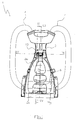
- Said shoulder support 1 commonly called a backpack, comprises a support body 2 that can selectively be associated with the motor group (not illustrated), a back 3 associated with said support body 2 and support means, in the example a pair of shoulder straps 4, to allow the transportation of the backpack by an operator.
- the motor group associated with the support 1 of the present invention supplies energy to a gardening tool (not illustrated) of the type known in the field, such as a hedgetrimmer, a secateur and the like.
- the motor group is generally a two-stroke endothermal motor group, fed with a petrol-oil mixture, with a cylinder capacity of about 35 cc.
- any other type of endothermal motor can be used, for example, as a four-stroke motor.
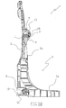
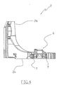
- the support body 2 has a shape, seen in section, substantially joined to form an L, as can be seen in figures 3A and 3B, comprising a support plane 2a arranged horizontally to support the motor and a fastening plane 2b to the back arranged vertically and tapered towards the top.
- the support plane 2a and the fastening plane 2b are made in a single piece, for example, by moulding.
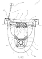
- the support plane 2a is provided with a cavity where a connection joint 6 (fig. 5) is arranged, known in the field and therefore not described in greater detail, to receive the motor group.
- connection joint 6 is associated with the support plane 2a through the interposition of a plurality of springs 7 arranged radially about the joint 6.
- Such springs 7, moreover, allow the transmission of vibrations of the motor to the backpack 1 and from this to the operator to be avoided.
- the support body 2 is provided with a first 8 and second projection 9 shaped to be coupled with corresponding first 10 and second recesses 11 formed in the back 3.
- the first projection 8 is arranged in the joining point between the support plane 2a and the fastening plane 2b, whereas the second projection 9 is arranged at the upper free end of the fastening plane 2b, i.e. the upper end distal from the joining point.
- the first projection 8 is made in a single piece with the support body 2 and is equipped at its end with a reinforcing cap 12 made from wear-resistant material.
- said first projection 8 has an arched configuration suitable for easing the falling to ground of the support body 2 in the presence of the downward push carried out by the weight of the motor.
- the second projection is in the form of a nose 9, shaped like a frustum of cone, fitted inside a passage channel formed at the upper end of the fastening plane 2b; the nose 9 is made from strong and hard-wearing material.
- the second recess 11, in which the portion of the nose 9 projecting from the fastening plane 2b removably inserts, has a configuration such as to allow the nose 9 integral with the fastening plane 2b to be easily slipped off in the presence of a downward thrust applied on the support plane 2a, such as that applied by the motor when it is positioned on the support plane 2a.
- the configuration of the back 3 and of the fastening plane 2b of the support body 2 are such as to allow a removable shape coupling.
- the back 3 and the fastening plane 2b mirror each other in the contact portions.
- engagement/disengagement means 13 are foreseen, rotatably associated with the backpack 1, which in a first configuration allow the fastening, and in a second configuration the complete detachment of the support body 2 and, therefore, of the motor.
- the disengagement means 13 reversibly lock the support body 2 against the back 3.
- the disengagement means 12 comprise a rotating element, known as a roller, suitable for rotating around a rotation axis (X-X) and consisting of two opposite coaxial hollow cylindrical bodies 14 with a bridge 15 interposed integrally associated with said cylindrical bodies 14 and, therefore, rotating with them, arranged distally from the rotation axis X-X and suitable for respectively taking up a locked position (fig. 3B) and an unlocked position (fig. 3A).
- the bridge 15, in the illustrated example, has a channel-shaped configuration having the concavity facing outwards with respect to the rotation axis X-X.
- the nose portion 9 opposite the one inserted in the second recess 11 has a headpiece 9' having a configuration such as to allow a shape coupling with the bridge 15, when they are in abutment (fig. 3B).
- the spring 16 applies a twisting action suitable for keeping the roller 13 in the locked position with the bridge 15 in abutment against the headpiece 9' of the nose 9.
- a cord 17 is associated with the roller 13 wound around the upper portion of at least one of the two cylindrical bodies 14 for at least one arc of circumference sufficient for allowing a rotation of the roller 13 such as to completely unlock the bridge 15, through a yank to the cord 17 itself.
- Such a cord 17 is provided, at the end opposite the one wound onto the roller 13, with a grip 18 and, moreover, to prevent the cord 17 from being able to hamper the work carried out by the operator, it is slotted into a channel 19 formed in the back 3 (fig. 2).
- the cord 17 can be suitably sheathed inside a sheath 20.
- Such a protective cover 5 can have an opening 5' to make the roller 13 at least partially accessible.
- the bridge 15 is in locked condition in contrast with the headpiece 9' of the nose 9 (fig. 3B) thanks to the twisting force applied by the spring 16.
- the fastening plane 2b of the support body 2 is associated with the back 3, with the first 8 and second projection 9 inserted in the respective recesses 10, 11 of the back 3.
- the operator In the presence of imminent danger deriving from the extreme proximity between the operator and the motor, for example the motor itself catching fire, the operator holds the grip 18 and yanks the cord 16 that, in the locked position, winds around the upper semicircumference portion of one of the two cylindrical bodies 14 of the roller 13.
- the weight of the motor associated with the support plane 2a applies a downward thrust such as to cause the detachment of the entire support body 2 from the back 3 pulling both the nose 9, now free from the bridge 15 in abutment, and the first projection 8 away from the respective recesses 10, 11 and causing the subsequent falling of the support body 2 with the motor.
- the operator in practice, remains only with the back 3 of the backpack 1 on his back.
- the restoration of the support body 2 on the back 3 is easy to carry out, since one only has to reposition the support body 2 with the projections 8, 9 in the respective recesses 10, 11 and keep the cord 17 pulled to then release it so as to allow the spring 16 to take the bridge 15 back into the locked position.
- the shoulder support for a motor group according to the present invention allows the requirements to be satisfied and the drawbacks mentioned in the introductory part of the present description with reference to the prior art to be overcome.
Landscapes
- Engineering & Computer Science (AREA)
- General Engineering & Computer Science (AREA)
- Mechanical Engineering (AREA)
- Life Sciences & Earth Sciences (AREA)
- Environmental Sciences (AREA)
- Structures Of Non-Positive Displacement Pumps (AREA)
- Motor Or Generator Frames (AREA)
Applications Claiming Priority (2)
| Application Number | Priority Date | Filing Date | Title |
|---|---|---|---|
| IT000020A ITRE20040020A1 (it) | 2004-03-15 | 2004-03-15 | Supporto a spalla per un gruppo motore |
| ITRE20040020 | 2004-03-15 |
Publications (3)
| Publication Number | Publication Date |
|---|---|
| EP1577602A2 true EP1577602A2 (fr) | 2005-09-21 |
| EP1577602A3 EP1577602A3 (fr) | 2005-11-16 |
| EP1577602B1 EP1577602B1 (fr) | 2008-03-05 |
Family
ID=34835610
Family Applications (1)
| Application Number | Title | Priority Date | Filing Date |
|---|---|---|---|
| EP05075526A Expired - Lifetime EP1577602B1 (fr) | 2004-03-15 | 2005-03-03 | Dispositif de support à l'épaule pour un groupe moteur |
Country Status (2)
| Country | Link |
|---|---|
| EP (1) | EP1577602B1 (fr) |
| IT (1) | ITRE20040020A1 (fr) |
Cited By (4)
| Publication number | Priority date | Publication date | Assignee | Title |
|---|---|---|---|---|
| WO2009008917A1 (fr) * | 2007-07-10 | 2009-01-15 | Mtd Products Inc. | Harnais pour aspirateur portatif |
| USD597708S1 (en) | 2007-07-10 | 2009-08-04 | Mtd Products Inc | Power tool harness |
| CN109890246A (zh) * | 2016-11-08 | 2019-06-14 | 意玛克股份公司 | 动力组件 |
| CN109922690A (zh) * | 2016-11-08 | 2019-06-21 | 意玛克股份公司 | 用于电动机的肩部支撑件 |
Family Cites Families (3)
| Publication number | Priority date | Publication date | Assignee | Title |
|---|---|---|---|---|
| US5011058A (en) * | 1990-01-30 | 1991-04-30 | Textron Inc. | Leaf blower back pack frame |
| US5732867A (en) * | 1996-11-26 | 1998-03-31 | Crush Innovative Sports Systems, Inc. | Releasable backpack |
| JP3398303B2 (ja) * | 1997-06-27 | 2003-04-21 | 本田技研工業株式会社 | 背負い式作業機 |
-
2004
- 2004-03-15 IT IT000020A patent/ITRE20040020A1/it unknown
-
2005
- 2005-03-03 EP EP05075526A patent/EP1577602B1/fr not_active Expired - Lifetime
Non-Patent Citations (1)
| Title |
|---|
| None |
Cited By (5)
| Publication number | Priority date | Publication date | Assignee | Title |
|---|---|---|---|---|
| WO2009008917A1 (fr) * | 2007-07-10 | 2009-01-15 | Mtd Products Inc. | Harnais pour aspirateur portatif |
| USD597708S1 (en) | 2007-07-10 | 2009-08-04 | Mtd Products Inc | Power tool harness |
| CN109890246A (zh) * | 2016-11-08 | 2019-06-14 | 意玛克股份公司 | 动力组件 |
| CN109922690A (zh) * | 2016-11-08 | 2019-06-21 | 意玛克股份公司 | 用于电动机的肩部支撑件 |
| US10959507B2 (en) | 2016-11-08 | 2021-03-30 | Emak S.P.A. | Power group |
Also Published As
| Publication number | Publication date |
|---|---|
| EP1577602A3 (fr) | 2005-11-16 |
| ITRE20040020A1 (it) | 2004-06-15 |
| EP1577602B1 (fr) | 2008-03-05 |
Similar Documents
| Publication | Publication Date | Title |
|---|---|---|
| CA2335738C (fr) | Manteau muni d'un harnais de sauvetage | |
| US5649504A (en) | Dual length leash system | |
| US9320672B2 (en) | Foldable walker apparatus | |
| US11154129B2 (en) | Wheelchair joystick retriever | |
| US9155376B2 (en) | Tool lanyard wrist cuff | |
| CN106417074B (zh) | 伸缩式宠物牵引绳 | |
| JPH10249070A (ja) | ラニヤードを通す孔をもつ折りたたみナイフ | |
| WO2011135739A1 (fr) | Raccord de laisse pour animaux | |
| EP1577602B1 (fr) | Dispositif de support à l'épaule pour un groupe moteur | |
| WO2008057622A2 (fr) | Palme avec toile ajustable | |
| CN112847667A (zh) | 手持式作业机器 | |
| JP7109834B2 (ja) | 引き紐組立体 | |
| US20070204805A1 (en) | Umbrella and leash | |
| JP5306027B2 (ja) | 間接活線工具支持具 | |
| US20180116378A1 (en) | Receiving Clamp for a Power Tool; Arrangement of Carrying System for a Power Tool and Receiving Clamp; and Arrangement of Carrying System, Receiving Clamp, and Power Tool | |
| US11957193B2 (en) | Load-assisting glove | |
| US20060266301A1 (en) | Adjustable length leash with an integrated waist belt | |
| US20080061573A1 (en) | Animal retrieval device | |
| US6275994B1 (en) | Rope-carrying garment | |
| US7909004B2 (en) | Cam-lock leash | |
| EP3579682A1 (fr) | Outil à main | |
| JP2017109290A (ja) | 作業補助具 | |
| JP3146675U (ja) | 位置調整治具 | |
| CN117283524A (zh) | 作业支援装置 | |
| KR20220028393A (ko) | 낚시용 손목 보호대 |
Legal Events
| Date | Code | Title | Description |
|---|---|---|---|
| PUAI | Public reference made under article 153(3) epc to a published international application that has entered the european phase |
Free format text: ORIGINAL CODE: 0009012 |
|
| AK | Designated contracting states |
Kind code of ref document: A2 Designated state(s): AT BE BG CH CY CZ DE DK EE ES FI FR GB GR HU IE IS IT LI LT LU MC NL PL PT RO SE SI SK TR |
|
| AX | Request for extension of the european patent |
Extension state: AL BA HR LV MK YU |
|
| PUAL | Search report despatched |
Free format text: ORIGINAL CODE: 0009013 |
|
| AK | Designated contracting states |
Kind code of ref document: A3 Designated state(s): AT BE BG CH CY CZ DE DK EE ES FI FR GB GR HU IE IS IT LI LT LU MC NL PL PT RO SE SI SK TR |
|
| AX | Request for extension of the european patent |
Extension state: AL BA HR LV MK YU |
|
| RIC1 | Information provided on ipc code assigned before grant |
Ipc: 7A 47L 5/36 B Ipc: 7A 45F 3/10 B Ipc: 7F 16M 3/00 B Ipc: 7F 16M 13/04 A Ipc: 7A 01D 34/90 B |
|
| 17P | Request for examination filed |
Effective date: 20060509 |
|
| AKX | Designation fees paid |
Designated state(s): IT TR |
|
| REG | Reference to a national code |
Ref country code: DE Ref legal event code: 8566 |
|
| 17Q | First examination report despatched |
Effective date: 20070122 |
|
| GRAP | Despatch of communication of intention to grant a patent |
Free format text: ORIGINAL CODE: EPIDOSNIGR1 |
|
| GRAS | Grant fee paid |
Free format text: ORIGINAL CODE: EPIDOSNIGR3 |
|
| GRAA | (expected) grant |
Free format text: ORIGINAL CODE: 0009210 |
|
| AK | Designated contracting states |
Kind code of ref document: B1 Designated state(s): IT TR |
|
| PLBE | No opposition filed within time limit |
Free format text: ORIGINAL CODE: 0009261 |
|
| STAA | Information on the status of an ep patent application or granted ep patent |
Free format text: STATUS: NO OPPOSITION FILED WITHIN TIME LIMIT |
|
| 26N | No opposition filed |
Effective date: 20081208 |
|
| P01 | Opt-out of the competence of the unified patent court (upc) registered |
Effective date: 20230605 |
|
| PGFP | Annual fee paid to national office [announced via postgrant information from national office to epo] |
Ref country code: TR Payment date: 20240223 Year of fee payment: 20 Ref country code: IT Payment date: 20240129 Year of fee payment: 20 |