EP1577681A1 - Medium-PFR Interpulsphasenmodulation zur Maximierung der Lücken im Dopplerbereich - Google Patents
Medium-PFR Interpulsphasenmodulation zur Maximierung der Lücken im Dopplerbereich Download PDFInfo
- Publication number
- EP1577681A1 EP1577681A1 EP05076240A EP05076240A EP1577681A1 EP 1577681 A1 EP1577681 A1 EP 1577681A1 EP 05076240 A EP05076240 A EP 05076240A EP 05076240 A EP05076240 A EP 05076240A EP 1577681 A1 EP1577681 A1 EP 1577681A1
- Authority
- EP
- European Patent Office
- Prior art keywords
- frequency
- phase
- clutter
- signal
- mainlobe
- Prior art date
- Legal status (The legal status is an assumption and is not a legal conclusion. Google has not performed a legal analysis and makes no representation as to the accuracy of the status listed.)
- Withdrawn
Links
- 238000000034 method Methods 0.000 claims abstract description 30
- 230000001427 coherent effect Effects 0.000 claims abstract description 9
- 230000008569 process Effects 0.000 claims description 4
- 230000010363 phase shift Effects 0.000 abstract description 22
- 230000006835 compression Effects 0.000 abstract description 9
- 238000007906 compression Methods 0.000 abstract description 9
- 230000000694 effects Effects 0.000 abstract description 4
- 238000001228 spectrum Methods 0.000 description 15
- 230000003595 spectral effect Effects 0.000 description 13
- 230000006870 function Effects 0.000 description 11
- 230000008901 benefit Effects 0.000 description 7
- 230000000737 periodic effect Effects 0.000 description 6
- 238000012545 processing Methods 0.000 description 6
- 238000010586 diagram Methods 0.000 description 5
- 230000000295 complement effect Effects 0.000 description 4
- 230000033001 locomotion Effects 0.000 description 3
- 230000002411 adverse Effects 0.000 description 2
- 238000013461 design Methods 0.000 description 2
- CNKHSLKYRMDDNQ-UHFFFAOYSA-N halofenozide Chemical compound C=1C=CC=CC=1C(=O)N(C(C)(C)C)NC(=O)C1=CC=C(Cl)C=C1 CNKHSLKYRMDDNQ-UHFFFAOYSA-N 0.000 description 2
- 238000005259 measurement Methods 0.000 description 2
- 238000012986 modification Methods 0.000 description 2
- 230000004048 modification Effects 0.000 description 2
- 238000013139 quantization Methods 0.000 description 2
- 241001388118 Anisotremus taeniatus Species 0.000 description 1
- 101000798707 Homo sapiens Transmembrane protease serine 13 Proteins 0.000 description 1
- 102100032467 Transmembrane protease serine 13 Human genes 0.000 description 1
- 230000015556 catabolic process Effects 0.000 description 1
- 230000008859 change Effects 0.000 description 1
- 238000004891 communication Methods 0.000 description 1
- 230000005574 cross-species transmission Effects 0.000 description 1
- 238000006731 degradation reaction Methods 0.000 description 1
- 238000005516 engineering process Methods 0.000 description 1
- 238000001914 filtration Methods 0.000 description 1
- 230000007246 mechanism Effects 0.000 description 1
- 230000008450 motivation Effects 0.000 description 1
- 238000011160 research Methods 0.000 description 1
- 230000004044 response Effects 0.000 description 1
- 238000012552 review Methods 0.000 description 1
- 238000010183 spectrum analysis Methods 0.000 description 1
- 230000007480 spreading Effects 0.000 description 1
- 238000013519 translation Methods 0.000 description 1
Images





Classifications
-
- G—PHYSICS
- G01—MEASURING; TESTING
- G01S—RADIO DIRECTION-FINDING; RADIO NAVIGATION; DETERMINING DISTANCE OR VELOCITY BY USE OF RADIO WAVES; LOCATING OR PRESENCE-DETECTING BY USE OF THE REFLECTION OR RERADIATION OF RADIO WAVES; ANALOGOUS ARRANGEMENTS USING OTHER WAVES
- G01S13/00—Systems using the reflection or reradiation of radio waves, e.g. radar systems; Analogous systems using reflection or reradiation of waves whose nature or wavelength is irrelevant or unspecified
- G01S13/02—Systems using reflection of radio waves, e.g. primary radar systems; Analogous systems
- G01S13/50—Systems of measurement based on relative movement of target
- G01S13/52—Discriminating between fixed and moving objects or between objects moving at different speeds
- G01S13/522—Discriminating between fixed and moving objects or between objects moving at different speeds using transmissions of interrupted pulse modulated waves
- G01S13/524—Discriminating between fixed and moving objects or between objects moving at different speeds using transmissions of interrupted pulse modulated waves based upon the phase or frequency shift resulting from movement of objects, with reference to the transmitted signals, e.g. coherent MTi
- G01S13/5242—Discriminating between fixed and moving objects or between objects moving at different speeds using transmissions of interrupted pulse modulated waves based upon the phase or frequency shift resulting from movement of objects, with reference to the transmitted signals, e.g. coherent MTi with means for platform motion or scan motion compensation, e.g. airborne MTI
-
- G—PHYSICS
- G01—MEASURING; TESTING
- G01S—RADIO DIRECTION-FINDING; RADIO NAVIGATION; DETERMINING DISTANCE OR VELOCITY BY USE OF RADIO WAVES; LOCATING OR PRESENCE-DETECTING BY USE OF THE REFLECTION OR RERADIATION OF RADIO WAVES; ANALOGOUS ARRANGEMENTS USING OTHER WAVES
- G01S7/00—Details of systems according to groups G01S13/00, G01S15/00, G01S17/00
- G01S7/02—Details of systems according to groups G01S13/00, G01S15/00, G01S17/00 of systems according to group G01S13/00
- G01S7/28—Details of pulse systems
- G01S7/282—Transmitters
Definitions
- the present invention relates generally to radar receivers, and more particularly to a method and apparatus for distinguishing between signals received from a desired target and those received from unwanted clutter.
- the final Doppler output of a pulse Doppler radar covers frequencies from -PRF/2 to PRF/2, where PRF is the Pulse Repetition Frequency of the radar's waveform. All other frequencies in the processed return outside of this range alias into this fundamental spectrum, and this fundamental spectrum is the basic Doppler ambiguity of the waveform used by the radar.
- PRF Pulse Repetition Frequency of the radar's waveform. All other frequencies in the processed return outside of this range alias into this fundamental spectrum, and this fundamental spectrum is the basic Doppler ambiguity of the waveform used by the radar.
- the signals of interest to the radar have Doppler shifts which exceed the fundamental waveform ambiguity.
- the position of any particular signal in the final spectral output of the radar can be found by subtracting integer multiples of the waveform PRF until the signal folds into the fundamental waveform ambiguity.
- the returning MLC signal as well as the target signal will be a phase modulated (PM) signal having a shifted carrier frequency with spectral lines precisely separated by the waveform PRF.
- PM phase modulated
- the goal in the choice of phase shift applied to each pulse over a Coherent Processing Interval (CPI) is to translate the carrier frequency by an amount that will cause the MLC return signal to be a multiple of the PRF. This fold will cause MLC signal to fold on top of the feedthrough signal in the digital processor.
- CPI Coherent Processing Interval
- the inventive concept applies a quantized linear phase code to the waveform over a Coherent Processing Interval (CPI) to accomplish the same frequency translation.
- the quantized linear phase code approximates a linear phase code from transmit pulse to transmit pulse but is constant over any one pulse.
- Figure 4A is a plot of these two phase codes as a function of time. Also shown in Figure 4A is the pulsed envelope of the transmit signal.
- the signal x(t) has its carrier frequency fc translated by the desired frequency shift f s Hz to the modulated carrier frequency f mod Hz.
- the signal contains harmonic spectral lines spaced at multiples of the PRF due to the periodic modulation (pulsed waveform with sawtooth phase error term). This is outlined in Carlson, chapter 6.2 of “Communication Systems", 1975 and Panter, chapter 7 of “Modulation, Noise and Spectral Analysis," 1965.
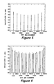
- Figures 5, 6 and 7 illustrate the above point.
- Figure 5 is a spectrum of a continuous sinusoid with a periodic sawtooth phase modulation.
- f min PRF/(2°)
- frequency shifts greater than f min are quantized to f min .
- the frequency of the mainlobe clutter must be known or estimated. This can be done by actively tracking mainlobe clutter during the acquisition process and modifying the clutter estimate based on IMU and head position data. Alternatively, if a high degree of accuracy is not required the mainlobe clutter frequency can be estimated from IMU and head position data alone depending upon system resolution requirements.
- the first is the errors due to a non-ideal phase shifter.
- the second is the error in the knowledge of MLC.
- the third is error in positioning MLC over feedthrough.
- Figure 10 is a comparison of an unshifted pulse Doppler signal and a shifted pulse Doppler signal (shifted 2 bins) using a 6 bit phase shifter with a 2 degree rms error. From Figure 10 it can be seen that for the shifted signal the peak sidelobes are down greater than 40 dB.
- Figure 12 is a plot of the width of MLC as a function of look angle for a mach 2 and 3 missile at either X or Ka Band. Figure 12 shows that MLC widths of greater than 1 kHz and closer to 2 kHz can be expected for reasonable missile velocities.
- the combination of errors in estimating MLC frequency coupled with the quantized frequency shift capability of the phase shifter contribute to the error in positioning MLC over feedthrough.
- the goal from a system point of view is to be able to place MLC to within plus or minus one half the width ofMLC around the feedthrough.
- the MLC frequency estimation error is taken as plus or minus 1/6 of the MLC (qualitatively described above) which leaves a plus or minus 1/3 positioning error due to the phase shifter quantization. In absolute terms the frequency steps must be less than 2/3 the bandwidth of the MLC signal.
- a flow diagram to implement the technique described above using digital signal processor 128 and computer 150 is shown. Since the location of the feedthrough is a function of the radar design, there is no need to measure its position; its location in the final Doppler output of the radar can be predicted apriori and stored in a lookup table.
- a track is established as shown in step 301 on the mainlobe clutter return, followed by measuring each dwell step 303 for the frequency and width of the clutter return. The measurements are used to update the clutter track step 305.
- the clutter frequency is predicted from the time of the track update to the current time, step 307.
- a phase modulating an exciter signal in the radar system to phase modulate a transmit signal processing step 309 is performed to control the phase of each pulse of the transmit signal 11.
- a changing phase of successive pulses in the transmit signal processing step 311 is performed as well as a holding the phase modulation constant over the duration of a pulse processing step 313. If the subroutine is continuing to track mainlobe clutter signals, then the subroutine continues with the tracking mainlobe clutter signals processing steps 303 and 305 and repeats the successive steps. If mainlobe clutter signals diminish then the subroutine will end.
- the inventive concept described herein is the realization that the mainlobe clutter and feedthrough interference can be made to overlap in the final doppler output of a coherent pulse doppler radar by placing interpulse modulation on the transmit signal.
- the selected phase modulation is derived from the linear phase ramp required to shift the mainlobe clutter spectrum into alignment, but held constant over the duration of a pulse.
- the constant phase shift across each pulse has no effect on the performance of intrapulse compression modulation and results in pulse to pulse phase shifts easily being accomplished with existing phase shifters.
- the technique takes advantage of the phase run out over the duration of a pulse between the applied modulation and linear phase ramp produced by the Doppler shift of the mainlobe clutter signal.
- the phase run out is a phase ramp with periodicity exactly matching that of the transmitted waveform with the resultant PM line spectrum aliasing at the waveform PRF thus causing the mainlobe clutter signal to alias into the feedthrough signal.
- the invention as described herein has application in any airborne MPRF radar application where there is a strong mainlobe clutter return.
- Applications include surveillance modes of avionics radars which use MPRF waveforms, terminal active missile seeker acquisition with MPRF waveforms, and MPRF track of low altitude targets by either avionics or missile seeker radars.
- mainlobe clutter return If the final spectral position of this return is not controlled, it adversely impacts the radar's ability to place the target in Doppler clear space-free from altitude return, feedthrough, eclipsing, and mainlobe clutter.
- the described technique causes feedthrough and mainlobe clutter to overlap in the final spectral output of the radar, thus isolating two of the major sources of interference to the same spectral region of the radar's output.
Landscapes
- Engineering & Computer Science (AREA)
- Radar, Positioning & Navigation (AREA)
- Remote Sensing (AREA)
- Computer Networks & Wireless Communication (AREA)
- Physics & Mathematics (AREA)
- General Physics & Mathematics (AREA)
- Radar Systems Or Details Thereof (AREA)
Applications Claiming Priority (3)
| Application Number | Priority Date | Filing Date | Title |
|---|---|---|---|
| US12054199P | 1999-02-17 | 1999-02-17 | |
| US120541P | 1999-02-17 | ||
| EP00913468A EP1153318A1 (de) | 1999-02-17 | 2000-02-14 | Medium-prf interpulsphasenmodulation zur maximierung der lücken im dopplerbereich |
Related Parent Applications (1)
| Application Number | Title | Priority Date | Filing Date |
|---|---|---|---|
| EP00913468A Division EP1153318A1 (de) | 1999-02-17 | 2000-02-14 | Medium-prf interpulsphasenmodulation zur maximierung der lücken im dopplerbereich |
Publications (1)
| Publication Number | Publication Date |
|---|---|
| EP1577681A1 true EP1577681A1 (de) | 2005-09-21 |
Family
ID=34839648
Family Applications (1)
| Application Number | Title | Priority Date | Filing Date |
|---|---|---|---|
| EP05076240A Withdrawn EP1577681A1 (de) | 1999-02-17 | 2000-02-14 | Medium-PFR Interpulsphasenmodulation zur Maximierung der Lücken im Dopplerbereich |
Country Status (1)
| Country | Link |
|---|---|
| EP (1) | EP1577681A1 (de) |
Citations (2)
| Publication number | Priority date | Publication date | Assignee | Title |
|---|---|---|---|---|
| US4586044A (en) * | 1983-01-24 | 1986-04-29 | Westinghouse Electric Corp. | Clutter positioning for electronically agile multi-beam radars |
| US5345239A (en) * | 1985-11-12 | 1994-09-06 | Systron Donner Corporation | High speed serrodyne digital frequency translator |
-
2000
- 2000-02-14 EP EP05076240A patent/EP1577681A1/de not_active Withdrawn
Patent Citations (2)
| Publication number | Priority date | Publication date | Assignee | Title |
|---|---|---|---|---|
| US4586044A (en) * | 1983-01-24 | 1986-04-29 | Westinghouse Electric Corp. | Clutter positioning for electronically agile multi-beam radars |
| US5345239A (en) * | 1985-11-12 | 1994-09-06 | Systron Donner Corporation | High speed serrodyne digital frequency translator |
Similar Documents
| Publication | Publication Date | Title |
|---|---|---|
| US11614531B2 (en) | Co-prime coded (CPC) doppler division multiplexing (DDM) MIMO radar method and system | |
| US11906618B2 (en) | MIMO radar apparatuses and MIMO radar methods | |
| US11662427B2 (en) | Method and system for frequency offset modulation range division MIMO automotive radar | |
| EP3835809B1 (de) | Verfahren und system für frequenzversatz-modulationsbereichsteilungs-mimo-automobilradar unter verwendung eines nur-i-kanalmodulationsmischers | |
| EP1754080B1 (de) | Radarsystem mit kurzen impulsen und gestufter frequenz | |
| US6518917B1 (en) | MPRF interpulse phase modulation for maximizing doppler clear space | |
| US5381151A (en) | Signal processing for ultra-wideband impulse radar | |
| US4450444A (en) | Stepped frequency radar target imaging | |
| US20040021600A1 (en) | Multiple time-interleaved radar operation using a single radar at different angles | |
| US7952516B2 (en) | System and method for coherent frequency switching in DDS architectures | |
| Jansen | Automotive radar Doppler division MIMO with velocity ambiguity resolving capabilities | |
| US5309160A (en) | Radar system and method having variable tracking range | |
| CN110632587A (zh) | 一种基于快速fmcw雷达的弱运动物体监测方法 | |
| JPH09178841A (ja) | レーダ・システム | |
| WO2020218925A1 (en) | Processing of radar signals for fmcw radar | |
| Thurn et al. | Concept and implementation of a PLL-controlled interlaced chirp sequence radar for optimized range–Doppler measurements | |
| JP2000147100A (ja) | パルスドップラレーダ装置 | |
| Mishra et al. | RaSSteR: Random sparse step-frequency radar | |
| US4894660A (en) | Range sidelobe reduction by aperiodic swept-frequency subpulses | |
| US5736956A (en) | Unlocked W-band receiver with coherent features | |
| Alter et al. | Ubiquitous radar: an implementation concept | |
| Mishra et al. | Range-Doppler decoupling and interference mitigation using cognitive random sparse stepped frequency radar | |
| EP1577681A1 (de) | Medium-PFR Interpulsphasenmodulation zur Maximierung der Lücken im Dopplerbereich | |
| US6765526B1 (en) | GMTI motion compensation | |
| US12174313B2 (en) | System and method for extending radar doppler range |
Legal Events
| Date | Code | Title | Description |
|---|---|---|---|
| PUAI | Public reference made under article 153(3) epc to a published international application that has entered the european phase |
Free format text: ORIGINAL CODE: 0009012 |
|
| 17P | Request for examination filed |
Effective date: 20050606 |
|
| AC | Divisional application: reference to earlier application |
Ref document number: 1153318 Country of ref document: EP Kind code of ref document: P |
|
| AK | Designated contracting states |
Kind code of ref document: A1 Designated state(s): DE FR GB |
|
| STAA | Information on the status of an ep patent application or granted ep patent |
Free format text: STATUS: THE APPLICATION HAS BEEN WITHDRAWN |
|
| 18W | Application withdrawn |
Effective date: 20060201 |