EP1577773A1 - Système multiprocesseur ayant un processeur de diagnostic pour sauver l'état du système et procédé d'exploitation d'un système multiprocesseur - Google Patents
Système multiprocesseur ayant un processeur de diagnostic pour sauver l'état du système et procédé d'exploitation d'un système multiprocesseur Download PDFInfo
- Publication number
- EP1577773A1 EP1577773A1 EP04006103A EP04006103A EP1577773A1 EP 1577773 A1 EP1577773 A1 EP 1577773A1 EP 04006103 A EP04006103 A EP 04006103A EP 04006103 A EP04006103 A EP 04006103A EP 1577773 A1 EP1577773 A1 EP 1577773A1
- Authority
- EP
- European Patent Office
- Prior art keywords
- multiprocessor system
- processor
- multiprocessor
- diagnostic
- diagnostic processor
- Prior art date
- Legal status (The legal status is an assumption and is not a legal conclusion. Google has not performed a legal analysis and makes no representation as to the accuracy of the status listed.)
- Withdrawn
Links
Images
Classifications
-
- G—PHYSICS
- G06—COMPUTING OR CALCULATING; COUNTING
- G06F—ELECTRIC DIGITAL DATA PROCESSING
- G06F11/00—Error detection; Error correction; Monitoring
- G06F11/07—Responding to the occurrence of a fault, e.g. fault tolerance
- G06F11/16—Error detection or correction of the data by redundancy in hardware
- G06F11/20—Error detection or correction of the data by redundancy in hardware using active fault-masking, e.g. by switching out faulty elements or by switching in spare elements
- G06F11/202—Error detection or correction of the data by redundancy in hardware using active fault-masking, e.g. by switching out faulty elements or by switching in spare elements where processing functionality is redundant
- G06F11/2038—Error detection or correction of the data by redundancy in hardware using active fault-masking, e.g. by switching out faulty elements or by switching in spare elements where processing functionality is redundant with a single idle spare processing component
-
- G—PHYSICS
- G06—COMPUTING OR CALCULATING; COUNTING
- G06F—ELECTRIC DIGITAL DATA PROCESSING
- G06F11/00—Error detection; Error correction; Monitoring
- G06F11/07—Responding to the occurrence of a fault, e.g. fault tolerance
- G06F11/0703—Error or fault processing not based on redundancy, i.e. by taking additional measures to deal with the error or fault not making use of redundancy in operation, in hardware, or in data representation
- G06F11/0706—Error or fault processing not based on redundancy, i.e. by taking additional measures to deal with the error or fault not making use of redundancy in operation, in hardware, or in data representation the processing taking place on a specific hardware platform or in a specific software environment
- G06F11/0721—Error or fault processing not based on redundancy, i.e. by taking additional measures to deal with the error or fault not making use of redundancy in operation, in hardware, or in data representation the processing taking place on a specific hardware platform or in a specific software environment within a central processing unit [CPU]
- G06F11/0724—Error or fault processing not based on redundancy, i.e. by taking additional measures to deal with the error or fault not making use of redundancy in operation, in hardware, or in data representation the processing taking place on a specific hardware platform or in a specific software environment within a central processing unit [CPU] in a multiprocessor or a multi-core unit
-
- G—PHYSICS
- G06—COMPUTING OR CALCULATING; COUNTING
- G06F—ELECTRIC DIGITAL DATA PROCESSING
- G06F11/00—Error detection; Error correction; Monitoring
- G06F11/07—Responding to the occurrence of a fault, e.g. fault tolerance
- G06F11/0703—Error or fault processing not based on redundancy, i.e. by taking additional measures to deal with the error or fault not making use of redundancy in operation, in hardware, or in data representation
- G06F11/079—Root cause analysis, i.e. error or fault diagnosis
-
- G—PHYSICS
- G06—COMPUTING OR CALCULATING; COUNTING
- G06F—ELECTRIC DIGITAL DATA PROCESSING
- G06F11/00—Error detection; Error correction; Monitoring
- G06F11/07—Responding to the occurrence of a fault, e.g. fault tolerance
- G06F11/0703—Error or fault processing not based on redundancy, i.e. by taking additional measures to deal with the error or fault not making use of redundancy in operation, in hardware, or in data representation
- G06F11/0793—Remedial or corrective actions
-
- G—PHYSICS
- G06—COMPUTING OR CALCULATING; COUNTING
- G06F—ELECTRIC DIGITAL DATA PROCESSING
- G06F11/00—Error detection; Error correction; Monitoring
- G06F11/07—Responding to the occurrence of a fault, e.g. fault tolerance
- G06F11/16—Error detection or correction of the data by redundancy in hardware
- G06F11/20—Error detection or correction of the data by redundancy in hardware using active fault-masking, e.g. by switching out faulty elements or by switching in spare elements
- G06F11/2002—Error detection or correction of the data by redundancy in hardware using active fault-masking, e.g. by switching out faulty elements or by switching in spare elements where interconnections or communication control functionality are redundant
Definitions
- the invention relates to a method for operating a multiple or multiprocessor system.
- the invention relates to it In addition, the operating according to the method multi or Multiprocessor system itself.
- the invention preferably relates to a multiprocessor system or a method for Operation of such a multiprocessor system for use in the field of automation of technical processes is.
- the multiprocessor system is then as an automation device realized or at least part of a Programmable controller.
- a multiprocessor or multiprocessor system stands in contrast to a single processor system by a plurality of Processing units, ie processors, ASICs or the like, in the following summary as work processors denotes, off.
- the individual work processors process at the same time individual independent control programs or independent parts of a single control program, in Also summarized below as a control program designated.
- the or each control program is in one of the respective Processor associated memory area stored.
- one of the work processors an error in particular an error while processing the respective control program, that leads to a system shutdown, remains either the entire multiprocessor system or at least the working processor affected by the error for Diagnostic purposes, so that in any case the function of the Overall system is affected.
- the multiprocessor system in case of error branches into an endless loop and thus virtually freeze the system state, since in the Infinite loop no changes to the data resulting in the Have led to errors, for. B. essential data of the processor context and the contents of the or each memory become.
- the system state conserved in this way can be analyzed at a later date to determine the cause of the error situation.
- the multiprocessor system provided that the system in Failure can independently trigger a reboot (boot), to resume productive operation as soon as possible.
- the availability of the multiprocessor system is indeed increased in the desired way, but it goes the data before that The occurrence of the error situation was present and expected have caused the error situation, lost, so that a later analysis of the cause of the error situation is impossible.
- a control system So a combination of automation devices, to avoid of critical situations in the controlled and / or supervised technical process often performed redundantly.
- Multiprocessor systems can work with two or more individual ones Multiprocessor systems be redundant.
- One Complete system with redundant single systems or single devices is referred to as a highly available system.
- the failed one System can be "frozen" with regard to its data so that for a later analysis of the cause the error situation are available. During the standstill of the failed system, however, that is actually intended high availability is not given.
- the system state of the error-free system that may not be backed up Also important for analyzing the cause of the error situation is.
- the invention is based on the object, a multiprocessor system and to provide a method for its operation, with to avoid any or all of the above disadvantages or at least reduce its impact to let.
- the above object is accordingly also with a solved corresponding method.
- This is in a procedure for operating a multiprocessor system of the above Art provided that the multiprocessor system communicative is connected to a diagnostic processor and that the diagnostic processor in case of a failure of the multiprocessor system ensures the system state of the multiprocessor system.
- the invention is based on the recognition that only one additional processor, namely the diagnostic processor, the Exclusively for the treatment of tasks related to the diagnosis of the respective multiprocessor system provided is, is suitable, all conceivable error situations handle.
- the diagnostic processor runs independently of the Work processors and is therefore at any time in the Able to monitor these.
- One or more work processors may be the diagnostic processor Initiate specified or predefinable measures.
- An error situation is detected by the diagnostic processor the communicative connection with the respective multiprocessor system. So z. B. be provided that the Multiprocessor system gives a kind of "life sign" by z. B. continuously the content of a particular memory location is switched.
- the diagnostic processor monitors such sign of life and guides in the absence of the sign of life immediately take the appropriate measures.
- the advantage of the invention is the decoupled structure of the whole system, namely the working processors on the one hand and the diagnostic processor, on the other hand, at Error in one or more work processors the function of the diagnostic processor is not concerned, so this the data needed to diagnose the error situation, ie can obtain the system state of the multiprocessor system, while this is stopped (frozen). This diagnostic data are then available for later evaluation.
- the backup includes the system state of the multiprocessor system a backup of the processor context each Working processor.
- the processor context includes all information, in particular contents of the processor's own registers, the behavior and operation of the work processor at the time of occurrence of the error situation influence.
- the backup of the system state of the multiprocessor system also a backup of the contents of the working memory of the affected or all work processors. To this Way can at a later time an error situation be detected, due to the processing of faulty Data, namely contents of the main memory, occurred is, for. B. by pulling a root from a negative Number or the like.
- both multiprocessor systems are preferred communicatively connected by means of a redundancy coupling, see above that they can exchange data with each other, which mutual synchronization are required and that with it the actual redundancy operation, ie the possibility at any time that one of the multiprocessor systems the tasks the other, failed multiprocessor system, first allow.
- a redundancy operation is special in the control and / or monitoring (critical) technical Processes, e.g. As chemical processes, of particular Interest, so that such redundant multiprocessor systems particularly preferably in the form of a redundant automation device with a first and a second such Multiprocessor system are running.
- the further redundant multiprocessor system does not have to be necessary at Site of the control room or the faulty multiprocessor system but can also be located in the premises of an automation service provider be constructed, the transmission the data collected by the diagnostic computer by remote data transmission, z. B. via the Internet, takes place.
- the method just described can be advantageous be added that not only the diagnostic processor of the faulty multiprocessor system the respective system state saves, but that all diagnostic processors the secure the respective system state.
- the System state of the redundant overall system recorded, so that at a later date also recognized error situations and can be investigated only on the basis of a special, both redundant multiprocessor systems have resulted in a mutually influencing constellation.
- the error-free multiprocessor system For signaling the redundancy loss, ie the state where there is no high availability is provided the error-free multiprocessor system sends a message via the redundancy loss to a higher-level unit, in particular a control room computer, settles. This can be over the Diagnostic processor of the error-free multiprocessor system respectively. Alternatively, it is also conceivable that the diagnostic processor the faulty multiprocessor system such Message drops. According to another favorable embodiment it is envisaged that such a declaration will only be if the duration of the redundancy loss is a predetermined or exceeds the specified time period. Such a message can namely be unnecessary if after a restart of the faulty Multiprocessor system of redundant operation immediately can be resumed. The benefit of such Message is evident. Due to such a message, if necessary Service personnel to maintain the redundant multiprocessor system causes. Alternatively, it is also possible that the each supervised or controlled technical process Redundancy loss is transferred to a safe state.
- control room computer via a communicative connection to the redundant multiprocessor system on the or each Diagnostic processor can access the system state of the or read each multiprocessor system.
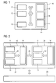
- FIG. 1 shows a multiprocessor system 10 with a plurality of processors, namely a first and second work processor 11, 12.
- the multiprocessor system includes 10 shows another processor, namely a diagnostic processor 13.
- the processors 11, 12, 13 have access to a memory 14 of the multiprocessor system 10.
- This memory 14 is in the form of individual storage areas 15, 16, 17, namely a first main memory area 15, a second Memory area 16 and a diagnostic processor memory area 17, organized.
- Each processor 11 to 13 Thus, a separate memory area 15 to 17 is assigned.
- the multiprocessor system 10 may also be one of the Number of processors 11 to 13 matched number of separate Memory include.
- the communicative connection allows at least communication between the two working processors 11, 12, z. B. for the purpose of data exchange and synchronization.
- the communicative connection enables communication from the diagnosis processor 13 to each working processor 11, 12, z. B. information about its status, in particular So a possible error situation, to receive.
- the communicative connection for each processor 11 to 13 have access to its respective assigned Memory range 15 to 17.
- the diagnostic processor 13 has due to the communicative Connection to the memory 14 Access to the memory areas 15, 16 of the working processors 11, 12 and on the own memory area, the diagnostic processor memory area 17th
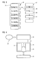
- FIG 2 shows that in its graph for reasons clarity reduced multiprocessor system 10 from 1, which together with another, functional the multiprocessor system 10 corresponding multiprocessor system 20 a redundant multiprocessor system 21 forms.
- Both multiprocessor systems 10, 20 are one through a Block arrow only indicated redundancy coupling 22 communicative connected.
- This redundancy coupling 22 is the guarantee the redundancy and the associated high availability of the overall system, the redundant multiprocessor system 21, required data exchange in per se handled in a known manner.
- z. B. each about a central unit of a programmable logic Control with at least two working processors 11, 12 and a diagnostic processor 13.
- the redundant multiprocessor system 21 then z. B. by the interconnection two such central units, which is due to the usual modular design of these devices and the connectivity a system bus is easily possible.
- Such a redundant Multiprocessor system 21 is preferred for control and / or Monitoring of technical processes used, being considered technical Process basically any automatable technical Process 23, so z. B. Production processes for production of goods and merchandise, chemical processes, energy production, Waste treatment and recycling, etc., into consideration comes.
- the respectively controlled or supervised technical Process 23 is also shown only stylized accordingly.
- each Multiprocessor system 10 Every working processor 11, 12 of each multiprocessor system 10, 20 introduces his memory area 15, 16 stored control program 25, 26, which in FIG 3 by a simple Flowchart is shown.
- the diagnostic processor 13 each Multiprocessor system 10, 20 carries its own control program, a diagnostic program 27, located in the diagnostic processor memory area 17 is stored.
- the diagnostic program 27 is for monitoring in the same multiprocessor system 10, 20 existing work processors 11, 12 intended. Therefore, the diagnostic program 27 contains a first one Sequence of instructions 28, with which, so to speak, in an infinite loop 29 a monitoring of the respective work processors 11, 12 takes place.
- This endless loop 29 is interrupted only if for at least one of the working processors 11, 12 by means of the instructions 28 an error situation, eg. B. a Absence of a "sign of life" was detected. Then it will be with first further instructions 30, which are part of the Diagnostic program 27 are a backup of the system health of the respective work processors. To secure the system state is provided in particular that both Work processors are stopped during the backup.
- the system state is a data set or a data sequence, the current status of a working processor 11, 12 represents. It preferably comprises the entire so-called Processor context, ie the contents of the processor-own Register, and possibly the contents of the working processor 11, 12 associated data memory or predetermined or specifiable excerpts thereof.
- Processor context ie the contents of the processor-own Register
- working processor 11, 12 associated data memory or predetermined or specifiable excerpts thereof.
- data storage is while a part of the working memory area 15, 16 understood, in particular the part of the working memory area 15, 16, the not for storing the respective control program 25, 26 is used and therefore only contains data that the control program 25, 26 processed or processed during operation.
- Second further instructions 31 for that of the error situation unaffected multiprocessor system 10, 20 is a Troubleshooting mode activated, either as a separately callable Subroutine on the respective work processor 11, 12 or as a separately invoked subroutine on the Diagnostic processor 13 can be realized.
- the troubleshooting operation provides at least one piece of information as a result going on, as the cause of the error situation, a hardware error comes into consideration. If such a hardware error as Result of the debugging operation is excluded, that of the error situation affected multiprocessor system 10, 20th restarted.
- This reboot can also be part of it of the troubleshooting operation, must not be necessary in Be implemented under the second additional instructions 31.
- After processing the second further instructions 31 branches the diagnostic program 27 again for continuous Monitoring of the working processors 11, 12.
- the secured system state is in the diagnostic processor memory area 17 filed. According to an advantageous embodiment can be provided that the secured system state or a message about the error situation and the Loss of high availability via a data line 32 at one at a central location in the technical process 23, for example a control room, arranged control room computer 33 is transmitted. This is shown in FIG. From here can be off either automatically or by user intervention further action is taken. If the control room computer 33 has access to the Internet 34, the as System state backed up data also to external service providers, for example, the supplier of the control hardware, in particular the redundant multiprocessor system 21, or the supplier of the control programs 25, 26, to analyze the error situation.
- external service providers for example, the supplier of the control hardware, in particular the redundant multiprocessor system 21, or the supplier of the control programs 25, 26, to analyze the error situation.
- a multiprocessor system 10, 20 indicated in addition a plurality of working processors 11, 12 at least one Diagnostic processor 13, which is used to monitor the working processors 11, 12 and in case of error to secure a System state either each work processor 11, 12 or the multiprocessor system 10, 20 is provided. If two or more such multiprocessor systems 10, 20 into one redundant multiprocessor system 21 are combined, For example, each diagnostic processor 13 can determine the system state of its own Multiprocessor system 10, 20 secure, so that in case of failure a system state of the overall system, namely of the redundant multiprocessor system 21, for a later Evaluation is available. The actual backup of the System state requires little time and is always possible since it is assumed that the diagnostic processor 13 of the respective error situation is not affected. After Backup can all work processors 11, 12 or all involved systems 10, 20 resume operation. The Analysis of the data obtained during the backup can offline, So without further operational degradation, done.
Landscapes
- Engineering & Computer Science (AREA)
- Theoretical Computer Science (AREA)
- Quality & Reliability (AREA)
- Physics & Mathematics (AREA)
- General Engineering & Computer Science (AREA)
- General Physics & Mathematics (AREA)
- Hardware Redundancy (AREA)
Priority Applications (1)
| Application Number | Priority Date | Filing Date | Title |
|---|---|---|---|
| EP04006103A EP1577773A1 (fr) | 2004-03-15 | 2004-03-15 | Système multiprocesseur ayant un processeur de diagnostic pour sauver l'état du système et procédé d'exploitation d'un système multiprocesseur |
Applications Claiming Priority (1)
| Application Number | Priority Date | Filing Date | Title |
|---|---|---|---|
| EP04006103A EP1577773A1 (fr) | 2004-03-15 | 2004-03-15 | Système multiprocesseur ayant un processeur de diagnostic pour sauver l'état du système et procédé d'exploitation d'un système multiprocesseur |
Publications (1)
| Publication Number | Publication Date |
|---|---|
| EP1577773A1 true EP1577773A1 (fr) | 2005-09-21 |
Family
ID=34833599
Family Applications (1)
| Application Number | Title | Priority Date | Filing Date |
|---|---|---|---|
| EP04006103A Withdrawn EP1577773A1 (fr) | 2004-03-15 | 2004-03-15 | Système multiprocesseur ayant un processeur de diagnostic pour sauver l'état du système et procédé d'exploitation d'un système multiprocesseur |
Country Status (1)
| Country | Link |
|---|---|
| EP (1) | EP1577773A1 (fr) |
Cited By (1)
| Publication number | Priority date | Publication date | Assignee | Title |
|---|---|---|---|---|
| FR3129005A1 (fr) | 2021-11-10 | 2023-05-12 | Vitesco Technologies | Procédé et dispositif de contrôle et commande d’un moteur de véhicule |
Citations (4)
| Publication number | Priority date | Publication date | Assignee | Title |
|---|---|---|---|---|
| EP0414379A2 (fr) * | 1989-08-01 | 1991-02-27 | Digital Equipment Corporation | Procédé de traitement d'erreurs de logiciel |
| EP0286856B1 (fr) * | 1987-04-16 | 1993-05-19 | BBC Brown Boveri AG | Système d'ordinateurs à tolérance de fautes |
| US5444859A (en) * | 1992-09-29 | 1995-08-22 | Amdahl Corporation | Method and apparatus for tracing multiple errors in a computer system subsequent to the first occurence and prior to the stopping of the clock in response thereto |
| WO2001016746A2 (fr) * | 1999-08-31 | 2001-03-08 | Sun Microsystems, Inc. | Procede et appareil destines a extraire une premiere panne et des informations sur le fonctionnement correspondantes depuis des dispositifs de systemes informatiques |
-
2004
- 2004-03-15 EP EP04006103A patent/EP1577773A1/fr not_active Withdrawn
Patent Citations (4)
| Publication number | Priority date | Publication date | Assignee | Title |
|---|---|---|---|---|
| EP0286856B1 (fr) * | 1987-04-16 | 1993-05-19 | BBC Brown Boveri AG | Système d'ordinateurs à tolérance de fautes |
| EP0414379A2 (fr) * | 1989-08-01 | 1991-02-27 | Digital Equipment Corporation | Procédé de traitement d'erreurs de logiciel |
| US5444859A (en) * | 1992-09-29 | 1995-08-22 | Amdahl Corporation | Method and apparatus for tracing multiple errors in a computer system subsequent to the first occurence and prior to the stopping of the clock in response thereto |
| WO2001016746A2 (fr) * | 1999-08-31 | 2001-03-08 | Sun Microsystems, Inc. | Procede et appareil destines a extraire une premiere panne et des informations sur le fonctionnement correspondantes depuis des dispositifs de systemes informatiques |
Cited By (4)
| Publication number | Priority date | Publication date | Assignee | Title |
|---|---|---|---|---|
| FR3129005A1 (fr) | 2021-11-10 | 2023-05-12 | Vitesco Technologies | Procédé et dispositif de contrôle et commande d’un moteur de véhicule |
| WO2023083703A1 (fr) | 2021-11-10 | 2023-05-19 | Vitesco Technologies GmbH | Procédé et dispositif de contrôle et commande d'un moteur de véhicule |
| US20240375669A1 (en) * | 2021-11-10 | 2024-11-14 | Vitesco Technologies GmbH | Method and device for monitoring and controlling a vehicle engine |
| US12606183B2 (en) * | 2021-11-10 | 2026-04-21 | Vitesco Technologies GmbH | Method and device for monitoring and controlling a vehicle engine |
Similar Documents
| Publication | Publication Date | Title |
|---|---|---|
| DE69228803T2 (de) | Wartungs-vorrichtung und verfahren ausgelöst durch wissenbasiertemaschine | |
| EP1297394B1 (fr) | Systeme de commande redondant avec calculateur pilote, et unite peripherique pour un tel systeme de commande | |
| EP2657797B1 (fr) | Procédé de fonctionnement d'un système d'automatisation redondant | |
| EP0685086B1 (fr) | Dispositif permettant de produire automatiquement une base de connaissances pour un system expert de diagnostic | |
| DE4317729A1 (de) | Programmierbare Steuereinheit | |
| EP2667269B1 (fr) | Procédé de fonctionnement d'un système d'automatisation redondant | |
| DE3751949T2 (de) | Verfahren zum Starten eines Untersystems in einem verteilten Verarbeitungssystem | |
| DE10324380B4 (de) | Programmierbare Steuerung mit CPU und Kommunikationseinheiten sowie Verfahren zur Steuerung derselben | |
| DE68922440T2 (de) | Gerät und Verfahren zur gleichzeitigen Einreichung von Fehlerunterbrechung und Fehlerdaten zu einem Unterstützungsprozessor. | |
| EP1743225B1 (fr) | Systeme d'automatisation redondant comprenant un automate programmable maitre et un automate programmable reserve | |
| EP3557356A1 (fr) | Procédé et système d'automatisation permettant le fonctionnement automatique sûr d'une machine ou d'un véhicule | |
| DE2647367A1 (de) | Redundante prozessteueranordnung | |
| EP1577773A1 (fr) | Système multiprocesseur ayant un processeur de diagnostic pour sauver l'état du système et procédé d'exploitation d'un système multiprocesseur | |
| DE10132313A1 (de) | Programmgesteuerte Einheit | |
| EP1239369A1 (fr) | Système informatique à tolérance de pannes et méthode d'utilisation d'un tel système | |
| DE3238692A1 (de) | Datenuebertragungssystem | |
| EP1019808B1 (fr) | Systeme et procede sensible pour traitement de signaux numeriques et procede de fonctionnement d'un systeme sensible | |
| DE2108836A1 (de) | Anordnung für ein Doppelrechnersystem | |
| WO2026068188A1 (fr) | Système et procédé de compensation de défaillances de composants | |
| DE102004050905A1 (de) | Monitoring-Einheit zur Überwachung und zur automatisierten Fehlerbehebung von medizinischen Applikationen | |
| DE19805819B4 (de) | Verfahren zur Überwachung von integrierten Schaltkreisen | |
| DE10228142B4 (de) | System zur Sicherung von Softwarekomponenten und/oder Computerprogrammen | |
| DE102019109353B3 (de) | Dynamische Anomalieerkennung und -behandlung | |
| EP1379952B1 (fr) | Unite a commande programmee | |
| DE102008033640B4 (de) | Betriebszeitagent zur proaktiven Erkennung einer Fehlfunktion und Verfahren zur vorzeitigen Erkennung einer Fehlfunktion |
Legal Events
| Date | Code | Title | Description |
|---|---|---|---|
| PUAI | Public reference made under article 153(3) epc to a published international application that has entered the european phase |
Free format text: ORIGINAL CODE: 0009012 |
|
| AK | Designated contracting states |
Kind code of ref document: A1 Designated state(s): AT BE BG CH CY CZ DE DK EE ES FI FR GB GR HU IE IT LI LU MC NL PL PT RO SE SI SK TR |
|
| AX | Request for extension of the european patent |
Extension state: AL LT LV MK |
|
| AKX | Designation fees paid | ||
| STAA | Information on the status of an ep patent application or granted ep patent |
Free format text: STATUS: THE APPLICATION IS DEEMED TO BE WITHDRAWN |
|
| 18D | Application deemed to be withdrawn |
Effective date: 20060322 |
|
| REG | Reference to a national code |
Ref country code: DE Ref legal event code: 8566 |