EP1577996B1 - Organe de retenue pour un faisceau de lignes - Google Patents
Organe de retenue pour un faisceau de lignes Download PDFInfo
- Publication number
- EP1577996B1 EP1577996B1 EP05101880A EP05101880A EP1577996B1 EP 1577996 B1 EP1577996 B1 EP 1577996B1 EP 05101880 A EP05101880 A EP 05101880A EP 05101880 A EP05101880 A EP 05101880A EP 1577996 B1 EP1577996 B1 EP 1577996B1
- Authority
- EP
- European Patent Office
- Prior art keywords
- holding device
- base
- holding
- limbs
- holding element
- Prior art date
- Legal status (The legal status is an assumption and is not a legal conclusion. Google has not performed a legal analysis and makes no representation as to the accuracy of the status listed.)
- Expired - Lifetime
Links
Images

Classifications
-
- H—ELECTRICITY
- H02—GENERATION; CONVERSION OR DISTRIBUTION OF ELECTRIC POWER
- H02G—INSTALLATION OF ELECTRIC CABLES OR LINES, OR OF COMBINED OPTICAL AND ELECTRIC CABLES OR LINES
- H02G3/00—Installations of electric cables or lines or protective tubing therefor in or on buildings, equivalent structures or vehicles
- H02G3/30—Installations of cables or lines on walls, floors or ceilings
- H02G3/32—Installations of cables or lines on walls, floors or ceilings using mounting clamps
Definitions
- the present invention relates to a holding element for cable strands, in particular cable strands, the type mentioned in the preamble of patent claim 1.
- Such holding elements are used to define cable strands, such as cable strands on components or other surfaces.
- a generic holding element in the form of a universal clamp EKS-UNI of the Applicant, it is known to arrange two holding members projecting from a base, which include an approximately circular lead-through space for a wiring harness regions.
- the free ends of the support members leave an opening to the passage space and are elastically expandable to insert a wiring harness with a diameter that is greater than the width of the opening, through the opening into the lead-through space or clipping.
- a mounting portion on the base of the holding element this can be by means of a fastener, such. As a screw or nail, are attached to a substrate or a component.
- Another disadvantage is that the vertically projecting from the base holding members provide a relatively large attack surface for flying or whirling objects, such as branches or smaller stones. Especially when using the retaining elements as a cable holder On railway lines it can lead to damage of the holding elements and possibly to a tearing of the cable from the holding elements.
- a holding element according to the preamble of claim 1 is made DE 2 530 255 A known.
- the object of the present invention is therefore to provide a holding element for cable strands, which is inexpensive to manufacture and which is less susceptible to damage from flying or whirling objects.
- the holding element is formed substantially flat-cone-shaped, wherein the holding members each form cone flanks of the holding element.
- the holding element according to the invention thus offers only small attack surfaces, which can easily be overcome by a moving object due to their inclined position, without being damaged themselves.
- the base of the retaining element can still be formed flat or flat-cylindrical.
- Conical or frusto-conical bodies including the subgroup of pyramidal or truncated pyramidal bodies, whose height parallel to the conical axis or perpendicular to the base is smaller than the greatest width of the base perpendicular to this conical axis, are considered flat-conical in the sense of the invention.
- the height of the holding element is at most half as large as the largest width of the base.
- a very flat habit of the holding element is produced, in which the possible lateral attack surfaces are minimized.
- the holding members are designed as clamping members whose inner sides facing the lead-through space are curved in a curved shape.
- the lead-through space is kept substantially circular.
- the preferably elastically resilient clamping members allow the insertion of cable strands in the passage space having a diameter which is greater than the width of the opening between the free ends of the clamping members or holding members.
- the base has a contact surface for attachment to a component, which is arched in the initial state in the direction of the lead-through space. This curvature of the approach surface is pressed when fixing the retaining element to a component or a substrate by means of a fastening means to the surface of the component / substrate, wherein a sealing of the attachment point takes place around the attachment portion.
- the holding element has a circular conical habit and the base has a round cross section.
- the holding element has a pyramidal habit and the base has a polygonal cross-section.
- the retaining element consists of a ductile, high-impact to elastomeric material, so that impacts of objects can also be absorbed and damped elastic.
- the holding member made of tire rubber, especially black colored tire rubber, which in addition to the elastic properties and a long life and UV resistance is achieved.
- the holding element is designed as a thin-walled hollow body, the z. B. has been produced by plastic injection molding.
- the retaining element is inexpensive to manufacture and has a high strength and impact resistance.
- the holding element has at least one closed cavity, whereby its impact resistance can be further increased.
- a holding element may, for. B. are produced in the injection-gas internal pressure process.
- a peripheral edge of the base is formed as a sealing lip, whereby the sealing properties of the retaining element relative to the attachment point are further improved.
- the retaining element consists of a thermoplastic material.
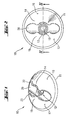
- holding element 10 shown has a circular conical shape which is determined essentially by two holding members 14, 15, which protrude from a base 11.
- the holding members 14, 15 form conical flanks 16, 17 which extend from the base 11 to free ends 22, 23 of the holding members 14, 15.
- a lead-through space 20 is spanned, the receiving a wiring harness 30, such.
- a cable with cable sheath 31 and cable strand 32 serves (see. Fig. 5 ).
- an opening 24 is arranged, via which the wiring harness 30 can be introduced into the lead-through space 20.
- the two holding members are curved on their inner sides 18, 19, which face the lead-through space 20 are arched.
- a mounting portion 12 Central in the area of the base 11 below the lead-through space 20 is a mounting portion 12 with an opening 13 for receiving a fastener 50, such.
- a fastener 50 such as a screw, a nail o. ⁇ ., Arranged.
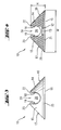
- the height H of the holding element 10 is less than half the size W (which here corresponds to the diameter of the circular base 11) of the base 11. Due to the flat conical shape of the holding element 10 offers this little attack surface for flying around or rolling objects such as stones, branches or the like. If an object strikes the retaining element 10, then it is guided away from the cone flanks 16, 17 via the retaining element 10 without damaging it.
- the holding element 10 in the present case consists of a high-impact, elastomeric material, such as tire rubber.
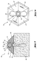
- Fig. 5 was the inventive holding element 10 by means of a fastening means 50, such as a screw, and a dowel 51 to a component 40, such. B. a railway sleeper, set.
- a fastening means 50 such as a screw
- a dowel 51 to a component 40, such. B. a railway sleeper, set.
- the approach surface 21 of the base 11 of the holding member 10 was pressed against the surface of the component 40 such that the attachment point is sealed below the mounting portion 12 on the voltage applied to the component 40 edge of the holding member 10 with the sealing lip 25.
- a wiring harness 30 is clipped in the form of a cable and is held there over the free ends 22, 23 of the holding members 14, 15.
- FIG. 6 Holding element 10 shown differs substantially only from the previously described, that it has a flat-pyramidal shape with a hexagonal base 11.
- the conical edges are formed by six pyramidal surfaces 27.
- FIG. 7 Holding element 10 shown consists of a high-impact thermoplastic material and differs essentially only from the previously described that it is formed as produced by plastic injection molding hollow body 26. Instead of a curved approach surface there, the sealing lip 25 is arranged axially slightly lower than the attachment portion 12.
- FIG. 8 Holding element 10 shown consists of a high-impact thermoplastic material and differs essentially only from the previously described that it is formed as produced in the injection-gas internal pressure process hollow body having at least one closed cavity 26. At the base 11 there is again a curved attachment surface 21 is formed.
Landscapes
- Engineering & Computer Science (AREA)
- Architecture (AREA)
- Civil Engineering (AREA)
- Structural Engineering (AREA)
- Installation Of Indoor Wiring (AREA)
- Clamps And Clips (AREA)
- Ropes Or Cables (AREA)
Claims (13)
- Élément de retenue pour faisceaux de conduites (30), en particulier pour faisceaux de câbles, comprenant une base (11) à appliquer sur un élément de construction (40), et comprenant au moins deux corps de retenue (14, 15) qui sont disposés latéralement par rapport à un espace de passage (20) pour la ligne de conduites (30) au nombre d'au moins une et qui font saillie par rapport à la base (11), caractérisé par un aspect sensiblement de cône aplati les corps de retenue (14, 15) formant chacun des flancs coniques (16, 17) de l'élément de retenue (10).
- Élément de retenue selon la revendication 1, caractérisé en ce que la hauteur (H) de l'élément de retenue (10) correspond au plus à la moitié de la largeur maximale (W) de la base (11).
- Élément de retenue selon la revendication 1 ou 2, caractérisé en ce que les corps de retenue (14, 15) sont conformés en corps de serrage dont les côtés intérieurs (18, 19) tournés vers l'espace de passage (20) sont cintrés sous forme arquée.
- Élément de retenue selon une des revendications 1 à 3, caractérisé en ce que la base (11) comporte, pour la poser sur un élément de construction (40), une surface de pose (21) qui, à l'état initial, est bombée en direction de l'espace de passage (20).
- Élément de retenue selon une des revendications 1 à 4, caractérisé par un aspect de cône de révolution, la base (11) présentant une section ronde.
- Élément de retenue selon une des revendications 1 à 4, caractérisé par un aspect pyramidal, la base (11) présentant une section polygonale.
- Élément de retenue selon une des revendication 1 à 6, caractérisé en ce que l'espace de passage (20) s'étend sensiblement parallèlement à la base (11).
- Élément de retenue selon une des revendications 1 à 7, caractérisé en ce qu'il est constitué d'un matériau élastomère à haute résistance aux chocs.
- Élément de retenue selon une des revendications 1 à 8, caractérisé en ce qu'il est constitué de caoutchouc pour pneumatiques.
- Élément de retenue selon une des revendications 1 à 8, caractérisé en ce qu'il est conformé en corps creux à paroi mince.
- Élément de retenue selon une des revendications 1 à 8 et 10, caractérisé en ce qu'il comporte au moins une cavité fermée (26).
- Élément de retenue selon une des revendications 1 à 8 et 10 à 11, caractérisé en ce qu'un bord périphérique de la base (11) est conformé en lèvre d'étanchéité (25).
- Élément de retenue selon une des revendications 1 à 8 et 10 à 12, caractérisé en ce qu'il est constitué de matière thermoplastique.
Applications Claiming Priority (2)
| Application Number | Priority Date | Filing Date | Title |
|---|---|---|---|
| DE102004013346A DE102004013346B3 (de) | 2004-03-17 | 2004-03-17 | Halteelement für Leitungsstränge |
| DE102004013346 | 2004-03-17 |
Publications (2)
| Publication Number | Publication Date |
|---|---|
| EP1577996A1 EP1577996A1 (fr) | 2005-09-21 |
| EP1577996B1 true EP1577996B1 (fr) | 2010-07-07 |
Family
ID=34833180
Family Applications (1)
| Application Number | Title | Priority Date | Filing Date |
|---|---|---|---|
| EP05101880A Expired - Lifetime EP1577996B1 (fr) | 2004-03-17 | 2005-03-10 | Organe de retenue pour un faisceau de lignes |
Country Status (4)
| Country | Link |
|---|---|
| EP (1) | EP1577996B1 (fr) |
| AT (1) | ATE473533T1 (fr) |
| DE (2) | DE102004013346B3 (fr) |
| ES (1) | ES2348156T3 (fr) |
Families Citing this family (2)
| Publication number | Priority date | Publication date | Assignee | Title |
|---|---|---|---|---|
| DE102014005326A1 (de) | 2014-04-11 | 2015-10-15 | Rolf Kranen | Vorrichtung zur Erzeugung einer Temperaturdifferenz |
| DE102019000909B4 (de) | 2019-02-08 | 2020-10-08 | Rolf Kranen | Druckkörper mit Kompressionskammer und Vorrichtung mit Druckkörper |
Family Cites Families (4)
| Publication number | Priority date | Publication date | Assignee | Title |
|---|---|---|---|---|
| DE2530235A1 (de) * | 1975-07-07 | 1977-02-03 | Horst Ing Grad Kessler | Selbstklebende kabel und kabel- befestigungselemente |
| DE7805954U1 (de) * | 1978-02-28 | 1978-10-05 | Konstruktive Kunststoff-Produkte Hoelzer Und Wulf Ohg, 8744 Mellrichstadt | Kunststoff-Halteclip für Leitungen und elektrische Kabel |
| CA2107707A1 (fr) * | 1993-10-05 | 1995-04-06 | Paul Cey | Support de tuyauterie |
| DE4426404C2 (de) * | 1994-07-26 | 1998-08-06 | Dehn & Soehne | An einem flächigen Untergrund anbringbare Anordnung zum lösbaren Halt von elektrischen Leitungsdrähten |
-
2004
- 2004-03-17 DE DE102004013346A patent/DE102004013346B3/de not_active Expired - Fee Related
-
2005
- 2005-03-10 DE DE502005009847T patent/DE502005009847D1/de not_active Expired - Lifetime
- 2005-03-10 AT AT05101880T patent/ATE473533T1/de active
- 2005-03-10 EP EP05101880A patent/EP1577996B1/fr not_active Expired - Lifetime
- 2005-03-10 ES ES05101880T patent/ES2348156T3/es not_active Expired - Lifetime
Also Published As
| Publication number | Publication date |
|---|---|
| ATE473533T1 (de) | 2010-07-15 |
| EP1577996A1 (fr) | 2005-09-21 |
| ES2348156T3 (es) | 2010-11-30 |
| DE102004013346B3 (de) | 2005-09-22 |
| DE502005009847D1 (de) | 2010-08-19 |
Similar Documents
| Publication | Publication Date | Title |
|---|---|---|
| DE2718170C3 (de) | Befestigungsclip für verkleidete Abdeckplatten, insbesondere für Kraftfahrzeuge | |
| DE10335394A1 (de) | Wischblatt zum Reinigen von Scheiben, insbesondere von Kraftfahrzeugen | |
| DE7811171U1 (de) | Halteclip für längliche Körper | |
| DE102013005830A1 (de) | Gleitschiene zum Spannen und Führen eines Endlostriebmittels und Verfahren zum Herstellen der Gleitschiene | |
| DE19650864B4 (de) | Anordnung zur Befestigung einer Beleuchtungseinrichtung an einem Fahrzeugteil | |
| DE102011009423B4 (de) | Montagehilfe für eine Belüftungsdüse und einen Belüftungskanal eines Kraftfahrzeuges, Belüftungsdüse, Belüftungskanal und Armaturentafel | |
| EP1577996B1 (fr) | Organe de retenue pour un faisceau de lignes | |
| EP1862356B1 (fr) | Clip de fixation | |
| DE10057947A1 (de) | Verbindungsanordnung zum lösbaren Verbinden zweier Bauteile mit einem hülsengeführten Bolzen, der mit einem ringförmigen Entriegelungsteil fest verbunden ist | |
| DE102019206750B4 (de) | Vorrichtung zum Ausgleichen von Toleranzen zwischen einem ersten Bauteil und einem zweiten Bauteil | |
| DE102006038040A1 (de) | Befestigungsclip | |
| DE10014745C2 (de) | Türfeststeller | |
| DE102011109757A1 (de) | Einführhilfe für Kabel | |
| EP2564077B1 (fr) | Elément pour un véhicule automobile | |
| EP2392496B1 (fr) | Rétroviseur extérieur doté d'un amortisseur à friction | |
| DE102016200358B4 (de) | Halteelement für die Anordnung eines separaten Designelements eines Fahrzeuges sowie Anordnung eines Designelements an einem Halteelement | |
| DE19954293C1 (de) | Zierleistenbefestigung, insbesondere für Kraftfwagen | |
| EP1971505B1 (fr) | Fixation de sac a gaz dans un module d'airbag au moyen d'une liaison serree | |
| DE102007045659A1 (de) | Dichtungsprofil zum Abdichten eines Bereichs zwischen einer Türsäule und einer Seitentür eines Kraftwagens | |
| DE102012007973A1 (de) | Vorrichtung zum Befestigen einer komprimierbarenFlächenstruktur an einem Karosserieteil eines Fahrzeuges | |
| DE102011056319A1 (de) | Luftleitvorrichtung | |
| DE102015122791A1 (de) | Profilschiene mit Griffelement | |
| EP3913758A1 (fr) | Boîte pour murs creux | |
| DE4234262A1 (de) | In einer Wand befestigter Verbinder mit selbsthaltendem Verbinderteil | |
| DE10246045B4 (de) | Verkleidungsteil |
Legal Events
| Date | Code | Title | Description |
|---|---|---|---|
| PUAI | Public reference made under article 153(3) epc to a published international application that has entered the european phase |
Free format text: ORIGINAL CODE: 0009012 |
|
| AK | Designated contracting states |
Kind code of ref document: A1 Designated state(s): AT BE BG CH CY CZ DE DK EE ES FI FR GB GR HU IE IS IT LI LT LU MC NL PL PT RO SE SI SK TR |
|
| AX | Request for extension of the european patent |
Extension state: AL BA HR LV MK YU |
|
| 17P | Request for examination filed |
Effective date: 20060321 |
|
| AKX | Designation fees paid |
Designated state(s): AT BE BG CH CY CZ DE DK EE ES FI FR GB GR HU IE IS IT LI LT LU MC NL PL PT RO SE SI SK TR |
|
| GRAP | Despatch of communication of intention to grant a patent |
Free format text: ORIGINAL CODE: EPIDOSNIGR1 |
|
| GRAS | Grant fee paid |
Free format text: ORIGINAL CODE: EPIDOSNIGR3 |
|
| GRAA | (expected) grant |
Free format text: ORIGINAL CODE: 0009210 |
|
| AK | Designated contracting states |
Kind code of ref document: B1 Designated state(s): AT BE BG CH CY CZ DE DK EE ES FI FR GB GR HU IE IS IT LI LT LU MC NL PL PT RO SE SI SK TR |
|
| REG | Reference to a national code |
Ref country code: GB Ref legal event code: FG4D Free format text: NOT ENGLISH |
|
| REG | Reference to a national code |
Ref country code: CH Ref legal event code: EP |
|
| REG | Reference to a national code |
Ref country code: IE Ref legal event code: FG4D |
|
| REF | Corresponds to: |
Ref document number: 502005009847 Country of ref document: DE Date of ref document: 20100819 Kind code of ref document: P |
|
| REG | Reference to a national code |
Ref country code: NL Ref legal event code: VDEP Effective date: 20100707 |
|
| PG25 | Lapsed in a contracting state [announced via postgrant information from national office to epo] |
Ref country code: SI Free format text: LAPSE BECAUSE OF FAILURE TO SUBMIT A TRANSLATION OF THE DESCRIPTION OR TO PAY THE FEE WITHIN THE PRESCRIBED TIME-LIMIT Effective date: 20100707 |
|
| LTIE | Lt: invalidation of european patent or patent extension |
Effective date: 20100707 |
|
| PG25 | Lapsed in a contracting state [announced via postgrant information from national office to epo] |
Ref country code: FI Free format text: LAPSE BECAUSE OF FAILURE TO SUBMIT A TRANSLATION OF THE DESCRIPTION OR TO PAY THE FEE WITHIN THE PRESCRIBED TIME-LIMIT Effective date: 20100707 Ref country code: NL Free format text: LAPSE BECAUSE OF FAILURE TO SUBMIT A TRANSLATION OF THE DESCRIPTION OR TO PAY THE FEE WITHIN THE PRESCRIBED TIME-LIMIT Effective date: 20100707 Ref country code: LT Free format text: LAPSE BECAUSE OF FAILURE TO SUBMIT A TRANSLATION OF THE DESCRIPTION OR TO PAY THE FEE WITHIN THE PRESCRIBED TIME-LIMIT Effective date: 20100707 |
|
| REG | Reference to a national code |
Ref country code: IE Ref legal event code: FD4D |
|
| PG25 | Lapsed in a contracting state [announced via postgrant information from national office to epo] |
Ref country code: PT Free format text: LAPSE BECAUSE OF FAILURE TO SUBMIT A TRANSLATION OF THE DESCRIPTION OR TO PAY THE FEE WITHIN THE PRESCRIBED TIME-LIMIT Effective date: 20101108 Ref country code: PL Free format text: LAPSE BECAUSE OF FAILURE TO SUBMIT A TRANSLATION OF THE DESCRIPTION OR TO PAY THE FEE WITHIN THE PRESCRIBED TIME-LIMIT Effective date: 20100707 Ref country code: IS Free format text: LAPSE BECAUSE OF FAILURE TO SUBMIT A TRANSLATION OF THE DESCRIPTION OR TO PAY THE FEE WITHIN THE PRESCRIBED TIME-LIMIT Effective date: 20101107 Ref country code: CY Free format text: LAPSE BECAUSE OF FAILURE TO SUBMIT A TRANSLATION OF THE DESCRIPTION OR TO PAY THE FEE WITHIN THE PRESCRIBED TIME-LIMIT Effective date: 20100707 Ref country code: BG Free format text: LAPSE BECAUSE OF FAILURE TO SUBMIT A TRANSLATION OF THE DESCRIPTION OR TO PAY THE FEE WITHIN THE PRESCRIBED TIME-LIMIT Effective date: 20101007 |
|
| PG25 | Lapsed in a contracting state [announced via postgrant information from national office to epo] |
Ref country code: SE Free format text: LAPSE BECAUSE OF FAILURE TO SUBMIT A TRANSLATION OF THE DESCRIPTION OR TO PAY THE FEE WITHIN THE PRESCRIBED TIME-LIMIT Effective date: 20100707 Ref country code: GR Free format text: LAPSE BECAUSE OF FAILURE TO SUBMIT A TRANSLATION OF THE DESCRIPTION OR TO PAY THE FEE WITHIN THE PRESCRIBED TIME-LIMIT Effective date: 20101008 |
|
| PG25 | Lapsed in a contracting state [announced via postgrant information from national office to epo] |
Ref country code: DK Free format text: LAPSE BECAUSE OF FAILURE TO SUBMIT A TRANSLATION OF THE DESCRIPTION OR TO PAY THE FEE WITHIN THE PRESCRIBED TIME-LIMIT Effective date: 20100707 Ref country code: IE Free format text: LAPSE BECAUSE OF FAILURE TO SUBMIT A TRANSLATION OF THE DESCRIPTION OR TO PAY THE FEE WITHIN THE PRESCRIBED TIME-LIMIT Effective date: 20100707 |
|
| PLBE | No opposition filed within time limit |
Free format text: ORIGINAL CODE: 0009261 |
|
| STAA | Information on the status of an ep patent application or granted ep patent |
Free format text: STATUS: NO OPPOSITION FILED WITHIN TIME LIMIT |
|
| PG25 | Lapsed in a contracting state [announced via postgrant information from national office to epo] |
Ref country code: EE Free format text: LAPSE BECAUSE OF FAILURE TO SUBMIT A TRANSLATION OF THE DESCRIPTION OR TO PAY THE FEE WITHIN THE PRESCRIBED TIME-LIMIT Effective date: 20100707 Ref country code: SK Free format text: LAPSE BECAUSE OF FAILURE TO SUBMIT A TRANSLATION OF THE DESCRIPTION OR TO PAY THE FEE WITHIN THE PRESCRIBED TIME-LIMIT Effective date: 20100707 Ref country code: CZ Free format text: LAPSE BECAUSE OF FAILURE TO SUBMIT A TRANSLATION OF THE DESCRIPTION OR TO PAY THE FEE WITHIN THE PRESCRIBED TIME-LIMIT Effective date: 20100707 Ref country code: RO Free format text: LAPSE BECAUSE OF FAILURE TO SUBMIT A TRANSLATION OF THE DESCRIPTION OR TO PAY THE FEE WITHIN THE PRESCRIBED TIME-LIMIT Effective date: 20100707 |
|
| 26N | No opposition filed |
Effective date: 20110408 |
|
| REG | Reference to a national code |
Ref country code: DE Ref legal event code: R097 Ref document number: 502005009847 Country of ref document: DE Effective date: 20110408 |
|
| BERE | Be: lapsed |
Owner name: HILTI AKTIENGESELLSCHAFT Effective date: 20110331 |
|
| PG25 | Lapsed in a contracting state [announced via postgrant information from national office to epo] |
Ref country code: MC Free format text: LAPSE BECAUSE OF NON-PAYMENT OF DUE FEES Effective date: 20110331 |
|
| REG | Reference to a national code |
Ref country code: FR Ref legal event code: ST Effective date: 20111130 |
|
| PG25 | Lapsed in a contracting state [announced via postgrant information from national office to epo] |
Ref country code: BE Free format text: LAPSE BECAUSE OF NON-PAYMENT OF DUE FEES Effective date: 20110331 |
|
| PG25 | Lapsed in a contracting state [announced via postgrant information from national office to epo] |
Ref country code: FR Free format text: LAPSE BECAUSE OF NON-PAYMENT OF DUE FEES Effective date: 20110331 |
|
| REG | Reference to a national code |
Ref country code: AT Ref legal event code: MM01 Ref document number: 473533 Country of ref document: AT Kind code of ref document: T Effective date: 20110310 |
|
| PG25 | Lapsed in a contracting state [announced via postgrant information from national office to epo] |
Ref country code: AT Free format text: LAPSE BECAUSE OF NON-PAYMENT OF DUE FEES Effective date: 20110310 |
|
| PG25 | Lapsed in a contracting state [announced via postgrant information from national office to epo] |
Ref country code: LU Free format text: LAPSE BECAUSE OF NON-PAYMENT OF DUE FEES Effective date: 20110310 |
|
| PG25 | Lapsed in a contracting state [announced via postgrant information from national office to epo] |
Ref country code: TR Free format text: LAPSE BECAUSE OF FAILURE TO SUBMIT A TRANSLATION OF THE DESCRIPTION OR TO PAY THE FEE WITHIN THE PRESCRIBED TIME-LIMIT Effective date: 20100707 |
|
| PG25 | Lapsed in a contracting state [announced via postgrant information from national office to epo] |
Ref country code: HU Free format text: LAPSE BECAUSE OF FAILURE TO SUBMIT A TRANSLATION OF THE DESCRIPTION OR TO PAY THE FEE WITHIN THE PRESCRIBED TIME-LIMIT Effective date: 20100707 |
|
| PGFP | Annual fee paid to national office [announced via postgrant information from national office to epo] |
Ref country code: ES Payment date: 20220525 Year of fee payment: 18 |
|
| PGFP | Annual fee paid to national office [announced via postgrant information from national office to epo] |
Ref country code: GB Payment date: 20230321 Year of fee payment: 19 Ref country code: DE Payment date: 20230321 Year of fee payment: 19 |
|
| PGFP | Annual fee paid to national office [announced via postgrant information from national office to epo] |
Ref country code: IT Payment date: 20230328 Year of fee payment: 19 Ref country code: CH Payment date: 20230402 Year of fee payment: 19 |
|
| PG25 | Lapsed in a contracting state [announced via postgrant information from national office to epo] |
Ref country code: ES Free format text: LAPSE BECAUSE OF NON-PAYMENT OF DUE FEES Effective date: 20230311 |
|
| REG | Reference to a national code |
Ref country code: ES Ref legal event code: FD2A Effective date: 20240426 |
|
| PG25 | Lapsed in a contracting state [announced via postgrant information from national office to epo] |
Ref country code: ES Free format text: LAPSE BECAUSE OF NON-PAYMENT OF DUE FEES Effective date: 20230311 |
|
| REG | Reference to a national code |
Ref country code: DE Ref legal event code: R119 Ref document number: 502005009847 Country of ref document: DE |
|
| REG | Reference to a national code |
Ref country code: CH Ref legal event code: PL |
|
| GBPC | Gb: european patent ceased through non-payment of renewal fee |
Effective date: 20240310 |
|
| PG25 | Lapsed in a contracting state [announced via postgrant information from national office to epo] |
Ref country code: DE Free format text: LAPSE BECAUSE OF NON-PAYMENT OF DUE FEES Effective date: 20241001 |
|
| PG25 | Lapsed in a contracting state [announced via postgrant information from national office to epo] |
Ref country code: GB Free format text: LAPSE BECAUSE OF NON-PAYMENT OF DUE FEES Effective date: 20240310 |
|
| PG25 | Lapsed in a contracting state [announced via postgrant information from national office to epo] |
Ref country code: GB Free format text: LAPSE BECAUSE OF NON-PAYMENT OF DUE FEES Effective date: 20240310 Ref country code: DE Free format text: LAPSE BECAUSE OF NON-PAYMENT OF DUE FEES Effective date: 20241001 Ref country code: CH Free format text: LAPSE BECAUSE OF NON-PAYMENT OF DUE FEES Effective date: 20240331 |
|
| PG25 | Lapsed in a contracting state [announced via postgrant information from national office to epo] |
Ref country code: IT Free format text: LAPSE BECAUSE OF NON-PAYMENT OF DUE FEES Effective date: 20240310 |