EP1578562B1 - Schleifscheiben-überwachung - Google Patents
Schleifscheiben-überwachung Download PDFInfo
- Publication number
- EP1578562B1 EP1578562B1 EP03789557A EP03789557A EP1578562B1 EP 1578562 B1 EP1578562 B1 EP 1578562B1 EP 03789557 A EP03789557 A EP 03789557A EP 03789557 A EP03789557 A EP 03789557A EP 1578562 B1 EP1578562 B1 EP 1578562B1
- Authority
- EP
- European Patent Office
- Prior art keywords
- grinding
- wheel
- force
- workpiece
- value
- Prior art date
- Legal status (The legal status is an assumption and is not a legal conclusion. Google has not performed a legal analysis and makes no representation as to the accuracy of the status listed.)
- Expired - Lifetime
Links
- 238000012544 monitoring process Methods 0.000 title claims abstract description 13
- 238000000034 method Methods 0.000 claims abstract description 41
- 230000008569 process Effects 0.000 claims description 14
- 238000005259 measurement Methods 0.000 claims description 11
- 230000008859 change Effects 0.000 claims description 2
- 230000000295 complement effect Effects 0.000 claims description 2
- 230000001960 triggered effect Effects 0.000 claims description 2
- 239000000463 material Substances 0.000 description 8
- 238000010586 diagram Methods 0.000 description 4
- 238000013459 approach Methods 0.000 description 2
- 238000012806 monitoring device Methods 0.000 description 2
- 238000012935 Averaging Methods 0.000 description 1
- 230000008901 benefit Effects 0.000 description 1
- 230000001351 cycling effect Effects 0.000 description 1
- 238000009713 electroplating Methods 0.000 description 1
- 230000002401 inhibitory effect Effects 0.000 description 1
- 238000003754 machining Methods 0.000 description 1
- 230000007246 mechanism Effects 0.000 description 1
- 239000002184 metal Substances 0.000 description 1
- 230000002093 peripheral effect Effects 0.000 description 1
- 238000012545 processing Methods 0.000 description 1
- 238000011536 re-plating Methods 0.000 description 1
- 238000009419 refurbishment Methods 0.000 description 1
- 230000004044 response Effects 0.000 description 1
- 238000012360 testing method Methods 0.000 description 1
Images


Classifications
-
- B—PERFORMING OPERATIONS; TRANSPORTING
- B24—GRINDING; POLISHING
- B24B—MACHINES, DEVICES, OR PROCESSES FOR GRINDING OR POLISHING; DRESSING OR CONDITIONING OF ABRADING SURFACES; FEEDING OF GRINDING, POLISHING, OR LAPPING AGENTS
- B24B49/00—Measuring or gauging equipment for controlling the feed movement of the grinding tool or work; Arrangements of indicating or measuring equipment, e.g. for indicating the start of the grinding operation
- B24B49/16—Measuring or gauging equipment for controlling the feed movement of the grinding tool or work; Arrangements of indicating or measuring equipment, e.g. for indicating the start of the grinding operation taking regard of the load
Definitions
- This invention concern methods and apparatus for monitoring the failure of grinding wheels, especially Electroplated CBN grinding wheels.
- This pattern is typical for a grinding wheel performing cylindrical grinding in which the grinding face of the wheel is plain, i.e. the grinding process is substantially uniform over the width of the wheel.
- the face of the wheel is not plain, but is required to include at least one and sometimes two or three peripheral ridges which it is found tend to wear away more quickly than the remaining surface of the wheel. This is particularly common when grinding sidewalls with undercuts.
- Each of the rims of the grinding wheel have to remove considerably more metal than the central region of the wheel and the power increase pattern for such a wheel when performing this type of grinding is rather different and there is only a minimal increase in power before the grinding material is completely stripped from the wheel due to the wheel wear occurring disproportionally over the width of the wheel.
- US-A-5044125 discloses a grinding machine including a force transducer mounted adjacent the wheelhead to measure the magnitude of the normal force occurring between the wheel and the workpiece. This measurement may be used to evaluate wheel sharpness as a function of the normal force measured.
- US-A-2001/0029148 describes a device for sharpening knives used in meat-processing machines. Contact between a sharpening tool and a knife may be detected by monitoring the motor current of the device that guides the sharpening tool towards the knife.
- the present invention is directed at a method of monitoring the wear of a grinding wheel in use, comprising measuring the force exerted by a wheelfeed drive which in use urges the wheel into grinding engagement with a workpiece so as to obtain a signal indicative of the force exerted between the wheel and workpiece normal to the grinding face of the wheel at the point of contact between the wheel and workpiece, wherein the wheelfeed drive includes an electrically powered motor, and the torque developed by the wheelfeed drive is proportional to the normal force between the wheel and workpiece.
- the method includes a further step of generating a warning signal indicative of imminent wheel failure when the value of the force indicative signal exceeds a predetermined threshold value, wherein the electrical power drawn by the wheelfeed drive motor during operation is proportional to the torque developed by the wheelfeed drive, and an indication of the force between wheel and workpiece is obtained by measuring the power demand made by the wheelfeed drive motor on its power supply.
- the power demand (and therefore the normal force between wheel and workpiece) will be proportional to the current drawn by the motor from its power supply.
- a force proportional signal can be obtained by measuring the current flow to the motor during grinding.
- the value of the force proportional signal obtained during a grinding process on a workpiece can be compared with a corresponding value obtained during the grinding process performed on a preceding similar workpiece, and a warning signal is generated if a current grinding force signal value differs from a preceding grinding force signal value by more than a predetermined amount.
- a mean value is computed for the force values measured during each of a succession of workpiece grinds on similar components and the value from the grinding of a current workpiece is compared with the mean value computed from a plurality of preceding workpiece grinds on similar components, and the warning signal is generated if the current force value differs from the mean force value by more than a predetermined amount.
- a timing device is reset at one point during each grinding process, and the force measurement is performed for a period of time determined by the timing device following the reset point, and the values of these force measurement signals (or a mean of these force measurement signal values) is/are compared with force measurement signal values from at least a preceding workpiece grind on a similar component, (or a mean of the force measurement value signals from a plurality of preceding workpiece grinds on similar components).
- the period of time is selected to correspond to the time during which a part of the grinding wheel which is liable to be subjected to the greatest wear during the grinding, is in grinding engagement with the workpiece.
- the grinding wheel includes a cylindrical surface and an annular ridge for grinding an undercut in a workpiece
- the ridge which is the part of the wheel surface which performs more work than the remainder of the wheel surface and is therefore liable to the greatest wear during grinding.
- the timer is preferably reset at a point during the grinding process, just in advance of when the annular ridge is to come into contact with the workpiece.
- the force value signals may vary in magnitude during grinding, and preferably therefore it is the peak value of the normal grinding force signal value which is measured and compared with a predetermined value, and the warning signal is generated if the measured peak force value signal exceeds a predetermined value.
- the peak force signal value obtained during the grinding of at least one of a succession of similar components may be stored and employed as a predetermined value with which subsequent peak force signal values obtained from grinding each of a succession of similar components is compared.
- the warning signal is only generated if the peak force signal value for a current grind differs from a stored peak force signal value by more than a predetermined difference.
- the warning signal may be employed to instigate a withdrawal of the wheel from grinding engagement with the workpiece.
- data logging of force is triggered X seconds after the start of grinding each workpiece, and disabled Y seconds after the start of grinding, where Y is greater than X.
- the instantaneous power demand of a linear motor drive which advances and maintains a grinding wheel in grinding contact with a workpiece is monitored during the same part of a grinding process performed on each of a succession of similar workpieces, and the warning signal is generated immediately the power demand exceeds a predetermined value.
- the warning signal may be employed to sound an alarm to alert a machine operator that a wheel change is required, and/or may be employed to disengage the wheel from the workpiece to prevent further wear occurring, and/or may instigate wheel withdrawal.
- Automated wheel replacement may follow by which the worn wheel is automatically demounted from its driving spindle and withdrawn from service, and is replaced with a fresh wheel ready to take over the grinding from the worn wheel.
- the method of the invention is of particular use in monitoring the wear of Electroplated CBN grinding wheels, particularly such wheels which are formed with an annular groove or an: annular radial protrusion, the profile of which will grind a complementary profile in the surface of a workpiece.
- the graphs in Figures 1 to 4 were obtained from measuring the normal force during the grinding of a crankshaft crankpin using Electroplated CBN wheels such as shown in Figure 5.
- the two wheels were used in succession with each wheel performing half of each plunge.
- the undercut portion of both wheels performed far more work than the remainder of the wheel and therefore in this situation it is important to monitor the grind in a period where only the undercut portion of the wheel is cutting.
- the normal force was monitored for the whole of each grind but data was only extracted during the first plunge of each wheel as this was grinding long sidewalls.
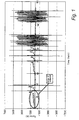
- the graph in Figure 1 shows the left hand wheel's normal force for the entire grind cycle.
- the four plunges for the pins are marked due to the cycling effect of the motor force required when grinding a pin.
- the rapid advances and retracts, in between plunges, can be seen as the large peaks on the normal force plot.
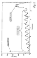
- the section of the plot that is of most interest can be clearly observed at the start of the grind and is circled in Figure 1.
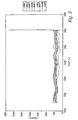
- the sidewall grind in this case, consists of 11 force cycles followed by the large force required to grind the diameter. This data was taken for every shaft over nearly 1,000 shafts at the end of which the CBN material on the left hand wheel's undercut had become stripped completely to the hub. Graphs were compiled using the values of peak force from the cycles that make up the sidewall grind. The first two force cycles were ignored as they were often very small or non-existent due to the variable sidewall stock. The graph in Figure 3 shows the 9 peak forces generated by the sidewall grind.
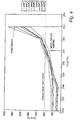
- the graph of Figure 4 shows the increase in the normal force on the sidewall grind, during the last 7 shafts ground, i.e. from 2,006 to 2,013 when wheel failure occurred. From Figure 4 it will be seen that the sidewall grind forces increased dramatically over the last 5 shafts ground. If a sidewall force limit of 1,040 Newtons had been set, then a warning signal would be displayed or sounded at shaft 2,911 which would have been two shafts prior to complete wheel failure. The amount of Electroplating left on the hub at that stage is probably just sufficient to allow the wheel to be replated and yet to obtain maximum life from the wheel.
- the invention is equally applicable to flat faced grinding wheels such as shown in Fig 6.
- the edge region of the wheel will perform greater amounts of work than the central region of the wheel.
- the sides of the wheel will therefore fail before the remainder of the wheel. This type of application would therefore still require the windowing approach provided by the invention.
- Fig 7 shows by way of a flow diagram the monitoring and decision making steps of a wheel monitoring system embodying the invention.
- the system assumes a formed CBN wheel to be grinding a formed region of a crankshaft and a linear motor wheelfeed.
- the monitoring device is brought into play when the side of the wheel (the sidewall) that performs the most work in use. Therefore the monitoring device is activated once the machine starts a sidewall feed for a journal grind.
- the signal monitored is the torque/force feedback value, direct from the linear motor drive unit.
- the values used are a percentage of the maximum linear motor current at standstill. This parameter is monitored every 30 mins and compared against a preset limit value. As the signal monitored tends to have some noise on it, then the value used to compare against the preset limit can be obtained by averaging the values of for example five total sidewall feeds.
- the system is adapted to look for a second value that exceeds the preset limit.
- the device informs the machine control to immediately suspend grinding and display a message regarding imminent wheel failure.
- a new wheel can then be mounted and grinding can continue.
- the removed wheel can be sent for replating.
- Fig 8 shows a wheel 10 carried on a spindle 12 of a wheel-head 14 itself carried by the primary 16 of a linear motor drive, the secondary of which 18 is secured to the machine bed 20.
- Current I to the primary 16 is supplied from a power supply 22 itself under the control of the machine computer 24. Grinding force between wheel 12 and workpiece 26 is proportional to the current I and since this value is available to the computer 22 the latter can generate an instantaneous numerical value F proportional to I, to yield a succession of values of F. Since it is important for the value of F to correspond to the same point in each grind, the computer 24 is programmed to calculate the value of F at a predetermined stage during the grinding of each of a succession of similar components.
- the windowing is effective to prevent the value of F from being calculated while the flat outer face of the wheel is being used to grind the pin, after the plunge grind step, and likewise during the fast advance and retraction of the wheel prior to and after grinding engagement.
- the threshold value for F (i.e. F t ) is input into the computer 24 and compared with the force value F and if the threshold value is exceeded a signal is generated by the computer to instigate an audible alarm 28. If desired the same signal may be employed to prevent the grinding of any more workpieces such as 26 by inhibiting the electric current to the linear motor 16, 18 after the current grinding cycle has been completed and the drive 16, 18 has retracted the wheelhead and disengaged the wheel from the workpiece.
- the threshold value F t is input via a data input device 32 and stored in the computer memory at 34 and compared with the running average in 30.
- the windowing of the monitored value of I (and therefore the updating of the value of F) is controlled so as only to occur when sidewall grinding is occurring, and to this end the algorithm includes an input corresponding to when this is occurring at 40, which controls the computation of F for I in step 42 and likewise the summing of the values of F to produce F n in 44.
- the division of F n by n is performed in 46 to provide the value of F n /n which is to be compared with F t in 30.
Landscapes
- Engineering & Computer Science (AREA)
- Mechanical Engineering (AREA)
- Constituent Portions Of Griding Lathes, Driving, Sensing And Control (AREA)
- Polishing Bodies And Polishing Tools (AREA)
- Treatment Of Sludge (AREA)
- Refinement Of Pig-Iron, Manufacture Of Cast Iron, And Steel Manufacture Other Than In Revolving Furnaces (AREA)
- Grinding And Polishing Of Tertiary Curved Surfaces And Surfaces With Complex Shapes (AREA)
Claims (18)
- Verfahren zur Überwachung der Abnutzung einer Schleifscheibe (10) während des Betriebs, welches das Messen der Kraft umfasst, die von einem Scheibenantrieb ausgeübt wird, der bei Betrieb die Schleifscheibe in schleifenden Kontakt mit einem Werkstück (26) drückt, so dass ein Signal empfangen wird, das die Kraft anzeigt, die zwischen der Scheibe und dem Werkstück senkrecht zur Schleiffläche der Scheibe am Kontaktpunkt zwischen der Scheibe und dem Werkstück ausgeübt wird, wobei der Scheibenantrieb einen elektrisch angetriebenen Motor (16, 18) umfasst, und das vom Scheibenantrieb entwickelte Drehmoment proportional zur Normal-Kraft zwischen der Scheibe (10) und dem Werkstück (26) ist, dadurch gekennzeichnet, dass das Verfahren einen weiteren Schritt einschließt, bei dem ein Warnsignal erzeugt wird, das einen unmittelbar bevorstehenden Ausfall der Schleifscheibe anzeigt, wenn der Wert des die Kraft anzeigenden Signals einen vorher bestimmten Schwellenwert übersteigt, wobei die elektrische Leistung, die von dem Scheibenantriebsmotor (16, 18) während des Betriebs bezogen wird, zu dem vom Scheibenantrieb entwickelten Drehmoment proportional ist, und wobei eine Anzeige der Kraft zwischen Scheibe und Werkstück durch Messen der Leistung erhalten wird, die vom Scheibenantriebsmotor seiner Energieversorgung (22) abgefordert wird.
- Verfahren nach Anspruch 1, bei dem der Motor (16, 18) mit elektrischem Strom von einer Energiequelle (22) versorgt wird, die eine im wesentlichen konstante elektromotorische Kraft (EMK) aufrechterhält, so dass die Leistungsanforderung, und daher die Normal-Kraft zwischen Scheibe (10) und Werkstück (26), dem Strom proportional ist, der vom Motor seiner Energieversorgung abgefordert wird.
- Verfahren nach Anspruch 2, bei dem während des Schleifens durch Messen des Stromflusses zum Motor (16, 18) ein der Kraft proportionales Signal erhalten wird.
- Verfahren nach einem der Ansprüche 1 bis 3, bei dem der Wert des der Kraft proportionalen Signals, das während des Schleifvorgangs an einem Werkstück (26) empfangen wird, verglichen wird mit einem entsprechenden Wert, der während des an einem vorhergehenden ähnlichen Werkstück ausgeführten Schleifvorgangs empfangen wurde, und ein Warnsignal erzeugt wird, wenn ein aktueller Schleifkraft-Signalwert von einem vorhergehenden Schleifkraft-Signalwert um mehr als einen vorherbestimmten Betrag abweicht.
- Verfahren nach Anspruch 4, bei dem ein Mittelwert für die Kraftwerte berechnet wird, die während jedes einzelnen einer Abfolge von Werkstückschliffen an ähnlichen Teilen gemessen wurden, und der Wert beim Schleifen eines gerade bearbeiteten Werkstücks mit dem Mittelwert verglichen wird, der aus einer Vielzahl von vorhergehenden Werkstückschliffen an ähnlichen Teilen berechnet wurde, und wobei das Warnsignal erzeugt wird, wenn der aktuelle Kraftwert vom mittleren Kraftwert um mehr als einen vorherbestimmten Betrag abweicht.
- Verfahren nach einem der Ansprüche 1 bis 4, bei dem eine Zeitsteuerungs-Einrichtung an einem Punkt während jedes Schleifverfahrens auf Reset gestellt wird, und nach dem Reset die Kraftmessung für einen Zeitraum durchgeführt wird, der von der Zeitsteuerungs-Einrichtung bestimmt wird, und die Werte dieser Kraftmessungssignale, oder ein Mittelwert dieser Kraftmessungssignale mit Signalwerten der Kraftmessung von mindestens einem vorhergehenden Werkstückschliff an einem ähnlichen Teil verglichen werden/wird, oder mit einem Mittelwert der angezeigten Werte der Kraftmessung aus einer Vielzahl von vorhergehenden Werkstückschliffen an ähnlichen Teilen.
- Verfahren nach Anspruch 6, bei dem der Zeitraum so gewählt wird, dass er der Zeit entspricht, während der ein Teil der Schleifscheibe (10), der der größten Abnutzung beim Schleifen ausgesetzt sein kann, sich in Schleifkontakt mit dem Werkstück (26) befindet.
- Verfahren nach Anspruch 7, bei dem die Schleifscheibe (10) eine zylinderförmige Fläche und eine ringförmige Rippe zum Schleifen eines Unterschnitts in ein Werkstück umfasst, und die Rippe derjenige Teil der Scheibenfläche ist, der mehr Arbeit leistet als die restliche Scheibenfläche und daher der größten Abnutzung während des Schleifens unterliegt, und wobei die Zeitsteuerung an einem Punkt während des Schleifvorgangs auf Reset gestellt wird, unmittelbar bevor die ringförmige Rippe mit dem Werkstück (26) in Kontakt kommen soll.
- Verfahren nach einem der Ansprüche 1 bis 4, bei dem die Kraftwertsignale während des Schleifens eine unterschiedliche Größenordnung haben, und der Spitzenwert des normalen Schleifkraftsignals gemessen und mit einem vorherbestimmten Wert verglichen wird, und wobei das Warnsignal erzeugt wird, wenn das Signal für den gemessenen Spitzenkraftwert einen vorherbestimmten Wert übersteigt.
- Verfahren nach Anspruch 9, bei dem das Signal für den Spitzenkraftwert während des Schleifens von mindestens einem in einer Reihe von ähnlichen Teilen gespeichert wird und als ein vorherbestimmter Wert benutzt wird, mit dem ein nachfolgendes Signal für den Spitzenkraftwert verglichen wird, das beim Schleifen eines anderen aus einer Reihe von ähnlichen Teilen erhalten wurde.
- Verfahren nach einem der Ansprüche 9 oder 10, bei dem das Warnsignal nur erzeugt wird, wenn das Signal für den Spitzenkraftwert für einen aktuellen Schliff von einem gespeicherten Signal für den Spitzenkraftwert um mehr als eine vorherbestimmte Differenz abweicht.
- Verfahren nach einem der Ansprüche 1 bis 11, bei dem das Warnsignal eingesetzt wird, um ein Zurückziehen der Scheibe aus dem schleifenden Kontakt mit dem Werkstück zu veranlassen.
- Verfahren nach einem der Ansprüche 1 bis 12, bei dem die Datenerfassung der Kraftwerte X Sekunden nach dem Start des Schleifens jedes einzelnen Werkstücks ausgelöst wird und Y Sekunden nach dem Start des Schleifens ausgeschaltet wird, wobei Y größer ist als X.
- Verfahren nach einem der Ansprüche 1 bis 13, bei dem die augenblickliche Leistungsanforderung eines Linearmotor-Antriebs (16, 18), der vorrückt und eine Schleifscheibe (10) in Schleifkontakt mit einem Werkstück (26) hält, während desselben Zeitraums eines Schleifvorgangs überwacht wird, der an jedem einer Reihe von ähnlichen Werkstücken durchgeführt wird, und ein Warnsignal sofort erzeugt wird, sobald die Leistungsanforderung einen vorherbestimmten Wert übersteigt.
- Verfahren nach einem der Ansprüche 1 bis 14, bei dem das Warnsignal eingesetzt wird, um einen Alarmton auszulösen, der einen Bedienungsmann der Maschine darauf aufmerksam macht, dass ein Wechsel der Schleifscheibe nötig ist und/oder das dafür eingesetzt wird, die Schleifscheibe vom Werkstück abzusetzen, um das Auftreten weiterer Abnutzung zu verhindern, und/oder das Zurückziehen der Schleifscheibe zu veranlassen.
- Verfahren nach einem der Ansprüche 1 bis 14, bei dem das Warnsignal den automatisierten Austausch der Schleifscheibe veranlasst, bei dem die Schleifscheibe automatisch aus dem schleifenden Kontakt zurückgezogen wird, von ihrer Antriebswelle automatisch abgebaut und aus dem Einsatz abgezogen wird, und automatisch durch eine neue Schleifscheibe ersetzt wird, die bereit ist, die Schleifarbeit der abgenutzten Schleifscheibe zu übernehmen.
- Verfahren nach einem der Ansprüche 1 bis 16, wenn es eingesetzt wird, um den Verschleiß von elektroplattierten CBN-Schleifscheiben zu überwachen.
- Verfahren nach Anspruch 17, bei dem die Schleifscheiben mit einer ringförmigen Rille oder einem ringförmigen radialen Vorsprung ausgebildet sind, deren Profil ein komplementäres Profil in die Oberfläche eines Werkstück schleift.
Applications Claiming Priority (5)
| Application Number | Priority Date | Filing Date | Title |
|---|---|---|---|
| GB0300004A GB0300004D0 (en) | 2003-01-02 | 2003-01-02 | Grinding wheel monitoring |
| GB0300004 | 2003-01-02 | ||
| GB0305496A GB0305496D0 (en) | 2003-01-02 | 2003-03-11 | Grinding wheel monitoring |
| GB0305496 | 2003-03-11 | ||
| PCT/GB2003/005590 WO2004060611A1 (en) | 2003-01-02 | 2003-12-22 | Grinding wheel monitoring |
Publications (2)
| Publication Number | Publication Date |
|---|---|
| EP1578562A1 EP1578562A1 (de) | 2005-09-28 |
| EP1578562B1 true EP1578562B1 (de) | 2007-02-14 |
Family
ID=31189615
Family Applications (1)
| Application Number | Title | Priority Date | Filing Date |
|---|---|---|---|
| EP03789557A Expired - Lifetime EP1578562B1 (de) | 2003-01-02 | 2003-12-22 | Schleifscheiben-überwachung |
Country Status (10)
| Country | Link |
|---|---|
| US (1) | US7153190B2 (de) |
| EP (1) | EP1578562B1 (de) |
| AT (1) | ATE353737T1 (de) |
| AU (1) | AU2003294137A1 (de) |
| CA (1) | CA2491745A1 (de) |
| DE (1) | DE60311882T2 (de) |
| ES (1) | ES2282720T3 (de) |
| GB (2) | GB2396981B (de) |
| MX (1) | MXPA05001223A (de) |
| WO (1) | WO2004060611A1 (de) |
Families Citing this family (15)
| Publication number | Priority date | Publication date | Assignee | Title |
|---|---|---|---|---|
| US20070295115A1 (en) * | 2006-06-22 | 2007-12-27 | Atlas Material Testing Technology Llc | Assembly and method for accelerated weathering with an automated programmable cycle |
| DE102008062081A1 (de) * | 2008-12-12 | 2010-06-17 | Mtu Aero Engines Gmbh | Ermittlung des Verschleißzustands eines Schleifwerkzeugs |
| ATE535344T1 (de) * | 2009-09-23 | 2011-12-15 | Supfina Grieshaber Gmbh & Co | Planschleifmaschine und verfahren zum betrieb und/oder zur wartung einer planschleifmaschine |
| US8517797B2 (en) * | 2009-10-28 | 2013-08-27 | Jtekt Corporation | Grinding machine and grinding method |
| US8660684B2 (en) * | 2010-06-04 | 2014-02-25 | The Gleason Works | Method of removing stock material from a workpiece by machining with a tool |
| CN102615594B (zh) * | 2012-04-20 | 2014-01-08 | 浙江师范大学 | 一种轴零件加工过程中的砂轮磨削力检测方法 |
| KR101974379B1 (ko) * | 2012-05-22 | 2019-09-06 | 삼성디스플레이 주식회사 | 기판 연마 장치 및 기판 연마 방법 |
| CN103358182A (zh) * | 2013-07-02 | 2013-10-23 | 国家电网公司 | 一种深孔钻床刀杆应力状态监测系统 |
| CN108426665B (zh) * | 2018-05-15 | 2023-05-16 | 中国工程物理研究院激光聚变研究中心 | 基于磨削阻力矩实时测量的砂轮磨损在线监测与报警装置 |
| CH715989B1 (de) * | 2019-03-22 | 2020-10-30 | Reishauer Ag | Verfahren zum kontinuierlichen Wälzschleifen von vorverzahnten Werkstücken. |
| EP3948702A4 (de) | 2019-03-29 | 2023-07-26 | Saint-Gobain Abrasives, Inc. | Lösungen für leistungsschleifen |
| WO2020206382A1 (en) | 2019-04-03 | 2020-10-08 | Saint-Gobain Abrasives, Inc. | Abrasive article, abrasive system and method for using and forming same |
| US11413780B1 (en) * | 2020-01-15 | 2022-08-16 | Securus Technologies, Llc | Automated nonuniform enclosure cutting tool |
| CN116604470B (zh) * | 2023-06-01 | 2026-02-06 | 淮阴工学院 | 一种多工位手术刀片磨削机的砂轮磨损状态确定方法 |
| FI131652B1 (en) * | 2024-02-23 | 2025-08-25 | Arata Tech Oy | Device and method for measuring abrasiveness of object |
Family Cites Families (13)
| Publication number | Priority date | Publication date | Assignee | Title |
|---|---|---|---|---|
| US4137677A (en) * | 1977-10-03 | 1979-02-06 | General Electric Company | Constant horsepower control for grinding wheel drives |
| JPS6056821A (ja) * | 1983-09-09 | 1985-04-02 | Honda Motor Co Ltd | 歯車研削機 |
| US4570389A (en) * | 1984-01-30 | 1986-02-18 | The Warner & Swasey Company | Method of adaptive grinding |
| FR2569365A1 (fr) * | 1984-08-27 | 1986-02-28 | Meseltron Sa | Procede et dispositif pour la commande de l'avance d'un outil vers une piece a travailler dans une machine-outil |
| US4653360A (en) * | 1985-05-07 | 1987-03-31 | The Cross Company | CNC turning machine |
| US4628643A (en) * | 1985-11-27 | 1986-12-16 | Ex-Cell-O Corporation | Grinding wheel infeed control method |
| SU1442874A1 (ru) * | 1986-03-07 | 1988-12-07 | Новгородский Политехнический Институт | Способ определени режущей способности шлифовального круга |
| US5042206A (en) * | 1988-09-02 | 1991-08-27 | Cincinnati Milacron-Heald Corp. | Method and apparatus for controlling grinding processes |
| US5044125A (en) * | 1988-09-02 | 1991-09-03 | Cincinnati Milacron-Heald Corp. | Method and apparatus for controlling grinding processes |
| JPH02176540A (ja) * | 1988-12-28 | 1990-07-09 | Nagase Iron Works Co Ltd | 工具の摩耗検出装置 |
| GB9615511D0 (en) * | 1996-07-24 | 1996-09-04 | Western Atlas Uk Ltd | Improvements relating to grinding methods and apparatus |
| EP0909611B1 (de) * | 1997-10-14 | 2002-01-30 | Agathon A.G. Maschinenfabrik | Verfahren zum Schleifen von Oberflächen von Werkstücken und Vorrichtung zur Durchführung des Verfahrens |
| DE10017719A1 (de) * | 2000-04-11 | 2001-10-18 | Knecht Maschb Gmbh | Vorrichtung zum Schleifen von Messern |
-
2003
- 2003-12-22 ES ES03789557T patent/ES2282720T3/es not_active Expired - Lifetime
- 2003-12-22 AU AU2003294137A patent/AU2003294137A1/en not_active Abandoned
- 2003-12-22 EP EP03789557A patent/EP1578562B1/de not_active Expired - Lifetime
- 2003-12-22 AT AT03789557T patent/ATE353737T1/de not_active IP Right Cessation
- 2003-12-22 DE DE60311882T patent/DE60311882T2/de not_active Expired - Lifetime
- 2003-12-22 CA CA002491745A patent/CA2491745A1/en not_active Abandoned
- 2003-12-22 US US10/537,163 patent/US7153190B2/en not_active Expired - Fee Related
- 2003-12-22 MX MXPA05001223A patent/MXPA05001223A/es active IP Right Grant
- 2003-12-22 WO PCT/GB2003/005590 patent/WO2004060611A1/en not_active Ceased
- 2003-12-22 GB GB0329606A patent/GB2396981B/en not_active Expired - Fee Related
-
2004
- 2004-12-30 GB GB0428429A patent/GB2411854A/en not_active Withdrawn
Also Published As
| Publication number | Publication date |
|---|---|
| ATE353737T1 (de) | 2007-03-15 |
| GB2396981A (en) | 2004-07-07 |
| WO2004060611A1 (en) | 2004-07-22 |
| GB0428429D0 (en) | 2005-02-02 |
| US7153190B2 (en) | 2006-12-26 |
| DE60311882T2 (de) | 2007-07-05 |
| GB2396981B (en) | 2004-12-15 |
| EP1578562A1 (de) | 2005-09-28 |
| AU2003294137A1 (en) | 2004-07-29 |
| DE60311882D1 (de) | 2007-03-29 |
| GB2411854A (en) | 2005-09-14 |
| MXPA05001223A (es) | 2005-05-16 |
| US20060035565A1 (en) | 2006-02-16 |
| CA2491745A1 (en) | 2004-07-22 |
| ES2282720T3 (es) | 2007-10-16 |
| GB0329606D0 (en) | 2004-01-28 |
Similar Documents
| Publication | Publication Date | Title |
|---|---|---|
| EP1578562B1 (de) | Schleifscheiben-überwachung | |
| JP3810090B2 (ja) | 工具状態の自動的モニター方法と装置 | |
| US5044125A (en) | Method and apparatus for controlling grinding processes | |
| EP2666591B1 (de) | Verfahren zur überwachung von schleifanomalien und vorrichtung zur überwachung von schleifanomalien | |
| US10532443B2 (en) | Method and grinding machine for grinding grooved workpieces | |
| US4551808A (en) | Tool wear sensors | |
| JP4860444B2 (ja) | 切削加工における異常検出方法 | |
| CN108637794B (zh) | 一种铣刀寿命控制方法 | |
| JP2016040072A (ja) | 工具異常検知方法 | |
| JP4979617B2 (ja) | 溝車のロープ溝加工装置およびロープ溝加工方法 | |
| JP6559102B2 (ja) | ドレス方法及びワークの研削方法 | |
| US6638142B2 (en) | Apparatus for sharpening blades | |
| JP2006281402A (ja) | 研削作業の状態を判定する方法及び同装置、並びに研削作業の制御方法 | |
| US6932675B1 (en) | Plated grinding wheel life maximization method | |
| CN116547109A (zh) | 用于控制和/或监测工件加工过程的方法 | |
| JPH0276678A (ja) | 研削工程を制御するための改良された装置と方法、および砥石を修正するための装置と方法 | |
| JP7484381B2 (ja) | びびり検出システム | |
| JP2003275947A (ja) | コールドシャー切断機のブレードの自動研削方法 | |
| CN120569680A (zh) | Cnc刀具寿命预测系统 | |
| JP7678647B2 (ja) | スポット溶接用電極の研磨方法 | |
| JP4670694B2 (ja) | ホーニング加工装置及びホーニング加工装置の制御方法 | |
| JPS62102975A (ja) | 研削盤の砥石修正装置 | |
| JP2013129028A (ja) | 研削異常監視方法および研削異常監視装置 | |
| BUREK et al. | Adoption of the Omative system in Inconel 718 turbine blade machining | |
| Saloni et al. | Control system evaluation and implementation for the abrasive machining process on wood. |
Legal Events
| Date | Code | Title | Description |
|---|---|---|---|
| PUAI | Public reference made under article 153(3) epc to a published international application that has entered the european phase |
Free format text: ORIGINAL CODE: 0009012 |
|
| 17P | Request for examination filed |
Effective date: 20041231 |
|
| AK | Designated contracting states |
Kind code of ref document: A1 Designated state(s): AT BE BG CH CY CZ DE DK EE ES FI FR GB GR HU IE IT LI LU MC NL PT RO SE SI SK TR |
|
| AX | Request for extension of the european patent |
Extension state: AL LT LV MK |
|
| DAX | Request for extension of the european patent (deleted) | ||
| RAP1 | Party data changed (applicant data changed or rights of an application transferred) |
Owner name: CINETIC LANDIS GRINDING LIMITED |
|
| GRAP | Despatch of communication of intention to grant a patent |
Free format text: ORIGINAL CODE: EPIDOSNIGR1 |
|
| GRAS | Grant fee paid |
Free format text: ORIGINAL CODE: EPIDOSNIGR3 |
|
| GRAA | (expected) grant |
Free format text: ORIGINAL CODE: 0009210 |
|
| AK | Designated contracting states |
Kind code of ref document: B1 Designated state(s): AT BE BG CH CY CZ DE DK EE ES FI FR GB GR HU IE IT LI LU MC NL PT RO SE SI SK TR |
|
| PG25 | Lapsed in a contracting state [announced via postgrant information from national office to epo] |
Ref country code: BE Free format text: LAPSE BECAUSE OF FAILURE TO SUBMIT A TRANSLATION OF THE DESCRIPTION OR TO PAY THE FEE WITHIN THE PRESCRIBED TIME-LIMIT Effective date: 20070214 Ref country code: SI Free format text: LAPSE BECAUSE OF FAILURE TO SUBMIT A TRANSLATION OF THE DESCRIPTION OR TO PAY THE FEE WITHIN THE PRESCRIBED TIME-LIMIT Effective date: 20070214 Ref country code: AT Free format text: LAPSE BECAUSE OF FAILURE TO SUBMIT A TRANSLATION OF THE DESCRIPTION OR TO PAY THE FEE WITHIN THE PRESCRIBED TIME-LIMIT Effective date: 20070214 Ref country code: FI Free format text: LAPSE BECAUSE OF FAILURE TO SUBMIT A TRANSLATION OF THE DESCRIPTION OR TO PAY THE FEE WITHIN THE PRESCRIBED TIME-LIMIT Effective date: 20070214 Ref country code: NL Free format text: LAPSE BECAUSE OF FAILURE TO SUBMIT A TRANSLATION OF THE DESCRIPTION OR TO PAY THE FEE WITHIN THE PRESCRIBED TIME-LIMIT Effective date: 20070214 Ref country code: LI Free format text: LAPSE BECAUSE OF FAILURE TO SUBMIT A TRANSLATION OF THE DESCRIPTION OR TO PAY THE FEE WITHIN THE PRESCRIBED TIME-LIMIT Effective date: 20070214 Ref country code: DK Free format text: LAPSE BECAUSE OF FAILURE TO SUBMIT A TRANSLATION OF THE DESCRIPTION OR TO PAY THE FEE WITHIN THE PRESCRIBED TIME-LIMIT Effective date: 20070214 Ref country code: CH Free format text: LAPSE BECAUSE OF FAILURE TO SUBMIT A TRANSLATION OF THE DESCRIPTION OR TO PAY THE FEE WITHIN THE PRESCRIBED TIME-LIMIT Effective date: 20070214 |
|
| REG | Reference to a national code |
Ref country code: GB Ref legal event code: FG4D |
|
| REG | Reference to a national code |
Ref country code: CH Ref legal event code: EP |
|
| REF | Corresponds to: |
Ref document number: 60311882 Country of ref document: DE Date of ref document: 20070329 Kind code of ref document: P |
|
| REG | Reference to a national code |
Ref country code: IE Ref legal event code: FG4D |
|
| PG25 | Lapsed in a contracting state [announced via postgrant information from national office to epo] |
Ref country code: SE Free format text: LAPSE BECAUSE OF FAILURE TO SUBMIT A TRANSLATION OF THE DESCRIPTION OR TO PAY THE FEE WITHIN THE PRESCRIBED TIME-LIMIT Effective date: 20070514 |
|
| PG25 | Lapsed in a contracting state [announced via postgrant information from national office to epo] |
Ref country code: BG Free format text: LAPSE BECAUSE OF EXPIRATION OF PROTECTION Effective date: 20070515 |
|
| PG25 | Lapsed in a contracting state [announced via postgrant information from national office to epo] |
Ref country code: PT Free format text: LAPSE BECAUSE OF FAILURE TO SUBMIT A TRANSLATION OF THE DESCRIPTION OR TO PAY THE FEE WITHIN THE PRESCRIBED TIME-LIMIT Effective date: 20070716 |
|
| NLV1 | Nl: lapsed or annulled due to failure to fulfill the requirements of art. 29p and 29m of the patents act | ||
| ET | Fr: translation filed | ||
| REG | Reference to a national code |
Ref country code: CH Ref legal event code: PL |
|
| REG | Reference to a national code |
Ref country code: ES Ref legal event code: FG2A Ref document number: 2282720 Country of ref document: ES Kind code of ref document: T3 |
|
| PG25 | Lapsed in a contracting state [announced via postgrant information from national office to epo] |
Ref country code: SK Free format text: LAPSE BECAUSE OF FAILURE TO SUBMIT A TRANSLATION OF THE DESCRIPTION OR TO PAY THE FEE WITHIN THE PRESCRIBED TIME-LIMIT Effective date: 20070214 |
|
| PLBE | No opposition filed within time limit |
Free format text: ORIGINAL CODE: 0009261 |
|
| STAA | Information on the status of an ep patent application or granted ep patent |
Free format text: STATUS: NO OPPOSITION FILED WITHIN TIME LIMIT |
|
| PG25 | Lapsed in a contracting state [announced via postgrant information from national office to epo] |
Ref country code: RO Free format text: LAPSE BECAUSE OF FAILURE TO SUBMIT A TRANSLATION OF THE DESCRIPTION OR TO PAY THE FEE WITHIN THE PRESCRIBED TIME-LIMIT Effective date: 20070214 Ref country code: CZ Free format text: LAPSE BECAUSE OF FAILURE TO SUBMIT A TRANSLATION OF THE DESCRIPTION OR TO PAY THE FEE WITHIN THE PRESCRIBED TIME-LIMIT Effective date: 20070214 |
|
| 26N | No opposition filed |
Effective date: 20071115 |
|
| PG25 | Lapsed in a contracting state [announced via postgrant information from national office to epo] |
Ref country code: GR Free format text: LAPSE BECAUSE OF FAILURE TO SUBMIT A TRANSLATION OF THE DESCRIPTION OR TO PAY THE FEE WITHIN THE PRESCRIBED TIME-LIMIT Effective date: 20070515 |
|
| PG25 | Lapsed in a contracting state [announced via postgrant information from national office to epo] |
Ref country code: MC Free format text: LAPSE BECAUSE OF NON-PAYMENT OF DUE FEES Effective date: 20071231 |
|
| GBPC | Gb: european patent ceased through non-payment of renewal fee |
Effective date: 20071222 |
|
| PG25 | Lapsed in a contracting state [announced via postgrant information from national office to epo] |
Ref country code: IE Free format text: LAPSE BECAUSE OF NON-PAYMENT OF DUE FEES Effective date: 20071224 |
|
| PG25 | Lapsed in a contracting state [announced via postgrant information from national office to epo] |
Ref country code: GB Free format text: LAPSE BECAUSE OF NON-PAYMENT OF DUE FEES Effective date: 20071222 |
|
| PG25 | Lapsed in a contracting state [announced via postgrant information from national office to epo] |
Ref country code: EE Free format text: LAPSE BECAUSE OF FAILURE TO SUBMIT A TRANSLATION OF THE DESCRIPTION OR TO PAY THE FEE WITHIN THE PRESCRIBED TIME-LIMIT Effective date: 20070214 |
|
| REG | Reference to a national code |
Ref country code: FR Ref legal event code: CD |
|
| PG25 | Lapsed in a contracting state [announced via postgrant information from national office to epo] |
Ref country code: CY Free format text: LAPSE BECAUSE OF FAILURE TO SUBMIT A TRANSLATION OF THE DESCRIPTION OR TO PAY THE FEE WITHIN THE PRESCRIBED TIME-LIMIT Effective date: 20070214 |
|
| PG25 | Lapsed in a contracting state [announced via postgrant information from national office to epo] |
Ref country code: LU Free format text: LAPSE BECAUSE OF NON-PAYMENT OF DUE FEES Effective date: 20071222 |
|
| PG25 | Lapsed in a contracting state [announced via postgrant information from national office to epo] |
Ref country code: TR Free format text: LAPSE BECAUSE OF FAILURE TO SUBMIT A TRANSLATION OF THE DESCRIPTION OR TO PAY THE FEE WITHIN THE PRESCRIBED TIME-LIMIT Effective date: 20070214 Ref country code: HU Free format text: LAPSE BECAUSE OF FAILURE TO SUBMIT A TRANSLATION OF THE DESCRIPTION OR TO PAY THE FEE WITHIN THE PRESCRIBED TIME-LIMIT Effective date: 20070815 |
|
| REG | Reference to a national code |
Ref country code: DE Ref legal event code: R082 Ref document number: 60311882 Country of ref document: DE Representative=s name: LOESENBECK UND KOLLEGEN, DE |
|
| REG | Reference to a national code |
Ref country code: FR Ref legal event code: CD Owner name: FIVES LANDIS LIMITED, GB Effective date: 20141203 Ref country code: ES Ref legal event code: PC2A Owner name: FIVE LANDIS LIMITED Effective date: 20141223 |
|
| REG | Reference to a national code |
Ref country code: DE Ref legal event code: R081 Ref document number: 60311882 Country of ref document: DE Owner name: FIVES LANDIS LIMITED, GB Free format text: FORMER OWNER: CINETIC LANDIS LTD., KEIGHLEY, GB Effective date: 20141211 Ref country code: DE Ref legal event code: R082 Ref document number: 60311882 Country of ref document: DE Representative=s name: LOESENBECK UND KOLLEGEN, DE Effective date: 20141211 |
|
| REG | Reference to a national code |
Ref country code: FR Ref legal event code: PLFP Year of fee payment: 13 |
|
| REG | Reference to a national code |
Ref country code: FR Ref legal event code: PLFP Year of fee payment: 14 |
|
| REG | Reference to a national code |
Ref country code: FR Ref legal event code: PLFP Year of fee payment: 15 |
|
| PGFP | Annual fee paid to national office [announced via postgrant information from national office to epo] |
Ref country code: DE Payment date: 20191210 Year of fee payment: 17 |
|
| PGFP | Annual fee paid to national office [announced via postgrant information from national office to epo] |
Ref country code: FR Payment date: 20191219 Year of fee payment: 17 |
|
| PGFP | Annual fee paid to national office [announced via postgrant information from national office to epo] |
Ref country code: IT Payment date: 20191227 Year of fee payment: 17 Ref country code: ES Payment date: 20200121 Year of fee payment: 17 |
|
| REG | Reference to a national code |
Ref country code: DE Ref legal event code: R119 Ref document number: 60311882 Country of ref document: DE |
|
| PG25 | Lapsed in a contracting state [announced via postgrant information from national office to epo] |
Ref country code: FR Free format text: LAPSE BECAUSE OF NON-PAYMENT OF DUE FEES Effective date: 20201231 Ref country code: IT Free format text: LAPSE BECAUSE OF NON-PAYMENT OF DUE FEES Effective date: 20201222 |
|
| PG25 | Lapsed in a contracting state [announced via postgrant information from national office to epo] |
Ref country code: DE Free format text: LAPSE BECAUSE OF NON-PAYMENT OF DUE FEES Effective date: 20210701 |
|
| REG | Reference to a national code |
Ref country code: ES Ref legal event code: FD2A Effective date: 20220221 |
|
| PG25 | Lapsed in a contracting state [announced via postgrant information from national office to epo] |
Ref country code: ES Free format text: LAPSE BECAUSE OF NON-PAYMENT OF DUE FEES Effective date: 20201223 |