EP1578647B1 - Detecteur d'impact - Google Patents
Detecteur d'impact Download PDFInfo
- Publication number
- EP1578647B1 EP1578647B1 EP03813998A EP03813998A EP1578647B1 EP 1578647 B1 EP1578647 B1 EP 1578647B1 EP 03813998 A EP03813998 A EP 03813998A EP 03813998 A EP03813998 A EP 03813998A EP 1578647 B1 EP1578647 B1 EP 1578647B1
- Authority
- EP
- European Patent Office
- Prior art keywords
- detector according
- sensor
- impact
- detector
- stiffness
- Prior art date
- Legal status (The legal status is an assumption and is not a legal conclusion. Google has not performed a legal analysis and makes no representation as to the accuracy of the status listed.)
- Expired - Lifetime
Links
Images

Classifications
-
- B—PERFORMING OPERATIONS; TRANSPORTING
- B60—VEHICLES IN GENERAL
- B60R—VEHICLES, VEHICLE FITTINGS, OR VEHICLE PARTS, NOT OTHERWISE PROVIDED FOR
- B60R21/00—Arrangements or fittings on vehicles for protecting or preventing injuries to occupants or pedestrians in case of accidents or other traffic risks
- B60R21/01—Electrical circuits for triggering passive safety arrangements, e.g. airbags, safety belt tighteners, in case of vehicle accidents or impending vehicle accidents
- B60R21/013—Electrical circuits for triggering passive safety arrangements, e.g. airbags, safety belt tighteners, in case of vehicle accidents or impending vehicle accidents including means for detecting collisions, impending collisions or roll-over
- B60R21/0136—Electrical circuits for triggering passive safety arrangements, e.g. airbags, safety belt tighteners, in case of vehicle accidents or impending vehicle accidents including means for detecting collisions, impending collisions or roll-over responsive to actual contact with an obstacle, e.g. to vehicle deformation, bumper displacement or bumper velocity relative to the vehicle
-
- B—PERFORMING OPERATIONS; TRANSPORTING
- B60—VEHICLES IN GENERAL
- B60R—VEHICLES, VEHICLE FITTINGS, OR VEHICLE PARTS, NOT OTHERWISE PROVIDED FOR
- B60R19/00—Wheel guards; Radiator guards, e.g. grilles; Obstruction removers; Fittings damping bouncing force in collisions
- B60R19/02—Bumpers, i.e. impact receiving or absorbing members for protecting vehicles or fending off blows from other vehicles or objects
- B60R19/48—Bumpers, i.e. impact receiving or absorbing members for protecting vehicles or fending off blows from other vehicles or objects combined with, or convertible into, other devices or objects, e.g. bumpers combined with road brushes, bumpers convertible into beds
- B60R19/483—Bumpers, i.e. impact receiving or absorbing members for protecting vehicles or fending off blows from other vehicles or objects combined with, or convertible into, other devices or objects, e.g. bumpers combined with road brushes, bumpers convertible into beds with obstacle sensors of electric or electronic type
-
- B—PERFORMING OPERATIONS; TRANSPORTING
- B60—VEHICLES IN GENERAL
- B60R—VEHICLES, VEHICLE FITTINGS, OR VEHICLE PARTS, NOT OTHERWISE PROVIDED FOR
- B60R21/00—Arrangements or fittings on vehicles for protecting or preventing injuries to occupants or pedestrians in case of accidents or other traffic risks
- B60R21/01—Electrical circuits for triggering passive safety arrangements, e.g. airbags, safety belt tighteners, in case of vehicle accidents or impending vehicle accidents
- B60R21/013—Electrical circuits for triggering passive safety arrangements, e.g. airbags, safety belt tighteners, in case of vehicle accidents or impending vehicle accidents including means for detecting collisions, impending collisions or roll-over
- B60R21/0132—Electrical circuits for triggering passive safety arrangements, e.g. airbags, safety belt tighteners, in case of vehicle accidents or impending vehicle accidents including means for detecting collisions, impending collisions or roll-over responsive to vehicle motion parameters, e.g. to vehicle longitudinal or transversal deceleration or speed value
-
- B—PERFORMING OPERATIONS; TRANSPORTING
- B60—VEHICLES IN GENERAL
- B60R—VEHICLES, VEHICLE FITTINGS, OR VEHICLE PARTS, NOT OTHERWISE PROVIDED FOR
- B60R21/00—Arrangements or fittings on vehicles for protecting or preventing injuries to occupants or pedestrians in case of accidents or other traffic risks
- B60R21/34—Protecting non-occupants of a vehicle, e.g. pedestrians
Definitions
- THE PRESENT INVENTION relates to an impact detector, and more particularly relates to an impact detector adapted to be mounted on a motor vehicle to detect a particular kind of impact, such as, for example, an impact with a pedestrian.
- a safety device includes an inflatable element having portions which extend up the "A"-Posts of the vehicle, to prevent the head of the pedestrian from being injured due to an impact with an "A"-Post of the vehicle.
- Another form of such a safety device lifts the rear part of the hood or bonnet of the vehicle, to distance the main region of the hood or bonnet from the underlying engine, thus enabling the hood or bonnet to deform if struck by the head of a pedestrian, consequently decreasing the risk of injury.
- Prior proposed impact detectors have used different kinds of sensors in the bumper of a motor vehicle, such as accelerometers, deformation sensors and force sensors.
- An output signal to activate a safety device to protect a pedestrian is generated if signals from the sensors are above or below predetermined threshold values.
- the senor In order to be able to discriminate an impact with a pedestrian from an impact with a lighter object, such as a bird, the sensor should ideally provide the output signal, in an accident situation in which an object is being struck, only in dependence upon a characteristic of the object being struck, such as the mass of that object, together possibly with other known and measurable parameters, such as the speed of the vehicle.
- US 2002/0033755 describes an impact detector for detecting and evaluating an impact and generating an output signal, the detector having at least one sensor to sense a variable that is dependent upon the nature of an impact, the sensor being mounted on or within an element adapted to be mounted on the front of a motor vehicle, the element having a deformable part with a predetermined stiffness, positioned to be deformed during an impact, the detector incorporating an evaluator to evaluate the output of the sensor and to generate the output signal when a predetermined threshold is exceeded.
- the present invention seeks to provide an improved impact detector.
- an impact detector for detecting and evaluating an impact and generating an output signal
- the detector having at least one sensor to sense a variable that is dependent upon the nature of an impact, the sensor being mounted on or within an element adapted to be mounted on the front of a motor vehicle, the element having a deformable part with a predetermined stiffness, positioned to be deformed during an impact, the stiffness varying in accordance with at least one parameter, the detector incorporating an arrangement to measure the said at least one parameter and an evaluator to evaluate the output of the sensor in combination with the degree of stiffness corresponding to the said at least one parameter as measured, and to generate the output signal when a predetermined threshold is exceeded.
- the senor is a force sensor.
- the senor comprises at least one accelerometer mounted to the element, the element being provided with yieldable supports by means of which the element may be mounted on the front of a motor vehicle.
- the senor comprises two said accelerometers, and wherein the element is provided with two said yieldable supports, each accelerometer being located on or in or adjacent a respective yieldable support.
- the senor comprises an elongate sensor mounted within the element, the sensor being located to have a force applied thereto when the deformable part of the element is deformed.
- the senor is a piezo-electric cable.
- the piezo-electric cables partially overlap each other.
- the senor is at least one pressure tube.
- the pressure tubes partially overlap each other.
- each pressure tube is of non-uniform cross-section, having part of the cross-section of substantial vertical extent and part of the cross-section of lesser vertical extent.
- the part of substantial vertical extent will be located forwardly of the part of lesser vertical extent.
- each pressure tube is provided with a vent hole.
- the deformable part of the element is formed of a deformable foam material.
- each pressure tube is formed as a channel within the foam material.
- the element incorporates a substantially rigid beam, the foam being mounted to the beam.
- the element is provided with at least one contact sensor, the detector including a logic arrangement so that said output signal is generated only when an output is provided by the evaluator and an output is provided by the said contact sensor.
- a plurality of contact sensor elements are provided, the logic arrangement being such that said output signal is generated when an output signal is provided by at least one of the contact sensor elements.
- a said at least one parameter comprises the thickness of the deformable part of the element, the deformable part of the element being of non-uniform thickness.
- the arrangement to measure said at least one parameter comprises an arrangement to measure the point of impact and to determine the thickness of the said element in accordance with the position of the point of impact.
- the means to measure the position of impact comprise an arrangement to compare the accelerations imparted to the two accelerometers, and to perform an algorithm.
- an analyser is provided to analyse signals from different elongate contact sensors to determine which contact sensor or combination of contact sensors is providing the signal, to determine the point of impact.
- an analyser is provided to analyse signals from different contact sensor elements to determine which contact sensor element or combination of sensor elements is providing a signal, to determine the position of the point of impact.
- said at least one parameter includes temperature and wherein at least one temperature sensor is provided to sense temperature.
- the temperature sensor is an analyser to analyse the capacitance across electrodes of the piezo-cable.
- a plurality of temperature sensors are provided.
- the identity of the temperature sensor or temperature sensors providing an output signal used by the evaluator is determined by the means that determine the position of the point of impact.
- the evaluator is configured additionally to evaluate a signal indicative of vehicle speed before the impact, and to generate the output signal only when the vehicle speed meets at least one criterion.
- the evaluator is configured to generate said output signal only when the vehicle speed is in excess of a first relatively low threshold and below a second relatively high threshold.
- the first threshold is 20 km per hour and the second threshold is 60 km per hour.
- a preferred embodiment of the invention also provides a detector as described above when mounted to the chassis of a vehicle, the stiffness of the part of the element between the sensor and the chassis being less than 1 / 10 of the total stiffness of the element.
- the detector is configured to receive a signal from a central accelerometer assembly indicative of the total deceleration applied to a vehicle on which the detector is mounted, to inhibit generation of said output signal if the said acceleration fulfils a predetermined criteria.
- a further preferred embodiment of the invention provides a detector as described above associated with a pedestrian protection device so that the said output signal will activate the pedestrian protection device.
- the mathematical analysis set out above only refers to the actual point of impact. If a sensor is provided which is located behind the point of impact, the signal is reduced with a factor equal to the quotient between the total stiffness and the stiffness behind the sensor, that is to say between the sensor and the chassis of a vehicle on which the member is mounted. To gain a high signal the stiffness in front of the sensor should be high and the stiffness behind the sensor should be low. However, to minimise the risk of injuring a pedestrian, the stiffness in front should be low. A good compromise can be achieved if the stiffness behind the sensor is less than 1 / 10 of the total stiffness of the vehicle bumper.
- That value can be used in an algorithm to determine whether or not the control signal for a safety device to protect a pedestrian should, or should not, be generated.
- the algorithm may, of course, rely on other parameters, such as the absolute vehicle speed, bearing in mind that a safety device to provide protection for a pedestrian may be considered to be effective only if the speed of impact with the pedestrian is greater than 20 km per hour, and less than 60 km per hour. At vehicle speeds less than 20 km per hour, or greater than 60 km per hour, most present-day safety devices intended to provide protection for pedestrians are thought to have no tangible beneficial effect.
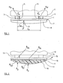
- a bumper (or fender)assembly 1 is mounted to the front part of a motor vehicle 2, such as a motor car, by two yieldable supports 3, 4 which are each located adjacent a respective end of the bumper.
- Each support 3, 4 may be in the form of a generally tubular housing formed of material having a thickness such that the housing will collapse or yield during a typical impact situation involving a pedestrian.
- Each support may thus be considered to be a "crash box".
- each accelerometer is mounted to the rear face of a relatively stiff beam 7 which forms part of the bumper 1.
- the front face of the beam 7 is provided with a yieldable covering 8 constituted, in the illustrated arrangement, by a "foam" block which is secured to the front face of the beam 7.
- the foam is a yieldable foam, the foam being of a uniform construction and thus having a known degree of "stiffness".
- the foam does not have a uniform thickness, however, and thus the absolute stiffness of the foam at any particular point is dependent upon the thickness of the foam at that particular point.
- the stiffness of the foam at any particular position or point could be calculated from design data, and the calculated stiffness could be stored in a memory in the form of a "look-up table".
- a look-up table it would be possible to calculate the position of the point of impact and then to determine the relevant stiffness, from the "look-up" table for that position.
- FIG. 2 illustrates a bumper 11 mounted to the front of the vehicle 12 by means of yieldable supports, or "crash boxes" 13, 14 of the type described above, located adjacent the opposed ends of the bumper 11.
- the bumper includes a substantially rigid beam 15 which extends between the supports 13 and 14, and, mounted to the front of the beam, is a foam element 16. Between the foam element and the beam is a sensor element 17, the sensor element either being in the form of a pressure tube or being in the form of a piezo-cable. The sensor is responsive to the total force applied to the bumper, regardless of the precise point at which the force is applied.
- a pressure tube is a tube having yieldable walls and containing a gas or liquid.
- the gas or liquid is in communication with a pressure sensor. If a force is applied to the tube, deforming the tube, the pressure of the gas or liquid rises, and this rise in pressure is sensed by the pressure sensor.
- a piezo-cable is an elongate cable having an elongate piezo-electric material between two elongate electrodes.
- a piezo-electric material is a material which, when compressed, generates an electric potential across opposed faces thereof.
- the piezo-electric material utilises a dielectric material with good piezo-electric properties.
- the piezo electric material is divided up into a plurality of small segments, there being individual electrodes associated with each segment, such that an output generated by the piezo-cable automatically indicates the precise point at which a force is applied to the cable.
- a cable may immediately identify a point of impact.
- the pressure tube could be divided into separate segments, which might overlap, or, alternatively a separate position sensor could be utilised to determine the position of the impact since, in the illustrated embodiment, the foam 16 is not of uniform thickness, and thus does not have a uniform overall stiffness characteristic and, as in the previously described embodiment, it will be appropriate to determine the position of impact so that the relevant stiffness may be determined for the point of impact from the stored information relating to the bumper.
- the effective stiffness of the beam at a point between the supports is less than k 2b the effective stiffness of the beam adjacent one of the supports 13. Also it is to be noted that k 1f is much less than k 2f , a point adjacent a support 13, because the foam is "softer" where it is thicker.
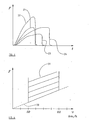
- Line 23 illustrates the force experienced at the vehicle speed v 1 for an impact with an object having a mass m 1 , in a region of effective stiffness k 2 as shown in Figure 2, adjacent a support 13 for the bumper 11.
- the overall shape of the line is similar to that described above, with the line rising towards a maximum force and then terminating abruptly.
- the maximum force is less than that for lines 21 or 22, but the time at which the force drops is later, as compared with the commencement of the force.
- line 24 illustrates the force experienced during an impact at a vehicle speed v 1 with an object having a mass m 2 where m 2 is greater than m 1 , again at a region where an effective stiffness k 2 is experienced.
- the line 24 rises gradually to a maximum and then terminates abruptly. The maximum, however, is greater than the maximum seen in line 23, and the termination of the force occurs at a later instant than it does in line 23.
- Figure 4 is a graphical figure indicating a plot between applied force and absolute vehicle speed. As mentioned above, it may be appropriate to select a predetermined range of vehicle speeds so that the control signal is only generated if the vehicle speed, before the impact, is within the selected range. In Figure 4 the range of 20 km to 60 km per hour has been selected, but this is an arbitrary selection. If an impact is detected while the vehicle is travelling within the speed range the control signal should only be generated if the force F exceeds a threshold. F 1 ⁇ v . k . m 1 where m 1 is the lower limit of the mass of the leg of a pedestrian.
- stiffness k is not independent of s, a or F .
- the stiffness k could also be dependent on v .
- Figure 5 shows different plots of F(t) for foam used in bumpers for different T and thus different k but with the same values for v and m .
- the first line 40 appearing in Figure 5 illustrates the effect with a relatively low temperature T1 and thus with a relatively high stiffness k 1 .
- the total time taken for completion of the illustrated cycle is relatively short.
- T2 and thus a lower foam stiffness k 2 , as shown at line 41, the total time taken is much longer but the maximum force is lower than for the line 40.
- the integral of the line 40 i.e. the area under the curve is the same as that for the line 41.
- a further bumper 51 is illustrated secured to the chassis 52 of a motor vehicle by means of two yieldable supports which may be in the form of crash boxes 53, 54.
- the bumper is provided with a relatively stiff rear beam 55, carrying, on its front face, a foam element 56.
- the foam element 56 of the illustrated embodiment has formed within it a channel constituting two adjacent pressure tubes 57, 58.
- the pressure tubes are identical and thus only the pressure tube 58 will be described.
- the pressure tube 58 comprises an elongate tube, there being a pressure sensor 59 within the tube providing an output on an output lead 60 to a processor 61.
- Each tube may be a channel formed in the foam material.
- the walls of the channel may be sealed and such sealing will be necessary if the foam is an open cell foam.
- the tube is provided with a vent hole 61 to atmosphere so that the tube normally contains air at atmospheric pressure.
- the interior of the tube does not have a uniform cross-section, but instead has a "trapezoidal" cross-section, the cross-section having a substantial dimension towards the very front of the bumper, and having a reducing section towards the rear of the bumper. The reason for this is that if such a tube is compressed, the change in volume, in the part of the tube which has the greater "height", is large relative to the total volume of the chamber.
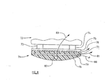
- Figure 8 illustrates a bumper 71 mounted to the chassis 72 of the motor vehicle by yieldable supports 73, 74 which may be in the form of "crash boxes" positioned adjacent the ends of the bumper 71.
- the bumper 71 incorporates a beam 75.
- a body 76 formed of a yieldable foam.
- a force sensor 77 in the form of one or more pressure tubes, or in the form of one or more piezo-cables.
- the sensor 77 provides an output signal shown schematically as the output 78.
- the contact sensor 79 may simply comprise two electrically conductive foils which initially are spaced a very short distance apart within the foam. Should any force be applied to the foam 76, the foils will be brought into electrical contact, thus effectively "shorting out", electric leads 80, 81 which are connected to the two foils.
- Other forms of contact sensor may be utilised, and it will be understood that before the control signal may be generated, firstly the contact sensor 79 must sense contact and, secondly in the manner described above, it must be determined that the mass of the object with which an impact is occurring meets the appropriate criteria.
- the contact sensor may include overlapping contact sensor elements to assist in the determining the position of the point of impact, as will be described more fully below.
- a temperature sensor 82 is incorporated within the foam body providing an output 83, and the output 83 may be fed to the processor so that in performing any calculations which relate to the stiffness of the foam body, appropriate adjustments may be made in accordance with the actual temperature.
- the capacitance between the electrodes of the cable which varies as a function of temperature, may be measured and analysed to provide a signal representative of temperature.
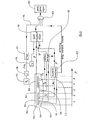
- Figure 9 illustrates a complete operative system forming a preferred embodiment of the invention.
- FIG 9 shows a bumper 100 which may be mounted on a motor vehicle in the manner discussed above, using two supports in the form of "crash boxes" adjacent the ends of the bumper.
- the bumper 100 incorporates a relatively rigid beam 101, to the front face of which is mounted a foam body 102.
- a force sensor 103 is provided between the foam body 102 and the beam 101, which may be in the form of a plurality of pressure tubes, or a piezo-cable.
- three elongate contact sensors 104, 105, 106 are provided, which are overlapping.
- the contact sensors 104, 105, 106 are within the foam body 102, being positioned in front of the force sensor 103.
- the rearmost contact sensors 104, 106 are spaced-apart, and the forward contact sensor 105 overlaps substantially half of each of the contact sensors 104, 106, and also extends across the space between the contact sensors 104 and 106. This relatively simple arrangement enables five discrete contact zones to be identified, using only three sensors.
- the sensors 104, 105, 106 are all connected to an evaluation unit 107 which determines which sensor or which combination of sensors have sensed contact, and provides an appropriate output signal indicative of the point where the impact has occurred to a processor 108 which carries out a pedestrian impact algorithm.
- the processor 108 is configured to determine, from a "look up table" stored in a memory the effective stiffness of the foam in the relevant zone. If any one of the contact sensors senses a contact, then an arming signal is provided to a logic component in the form of an inhibitable "AND gate” 109, which also receives an input from the processor 108.
- a plurality of temperature sensors 110, 111 and 112 are provided within the bumper.
- the temperature sensors sense the temperature in different regions of the foam body 102.
- the output signal from the evaluation unit 107 is passed to a temperature selection unit 113 which receives signals from the three temperature sensors 110, 111 and 112.
- the temperature of an appropriate temperature sensor, or of a combination of temperature sensors is passed, by the temperature selection unit 113 to the processor 108 carrying out the pedestrian impact algorithm.
- the actual temperature may be used to adjust the selected value of stiffness appropriately.
- the processor 108 also receives an input indicating the speed of the vehicle immediately preceding the impact from the vehicle speedometer unit 114.
- a further accelerometer 115 is provided which is mounted on the main chassis of the vehicle, preferably at a central location.
- the accelerometer 115 is therefore responsive to the total acceleration of the vehicle, and, as will become clearer, this accelerometer is utilised to determine if the vehicle has been involved in an impact with a very heavy object, such as another vehicle, in which case it would be inappropriate to deploy the safety device intended to provide protection for a pedestrian.
- the output of the accelerometer 115 is integrated at an integrator 116, to provide a signal representative of the total velocity change of the vehicle during a predetermined period of time. ⁇ t 0 t a c . d t
- the output of the integrator is fed to a discriminator 117.
- the discriminator is intended to determine whether the change in velocity is such that an impact has occurred with an object which is much heavier than a pedestrian. Should the discriminator 117 determine that the change in velocity exceeds a predetermined threshold, which may indicate that an impact has occurred with an object heavier than a pedestrian, then a signal is generated on lead 118 which inhibits the AND-gate 109, thus preventing the control signal on the output of the AND-gate from being generated.
- a low pass filter could be applied to the acceleration signal, or a "sliding window" mean value may be calculated, this being the mean value, at any instant, over a preceding predetermined period of time.
- the output of the AND-gate 109 is provided to the safety device in the form of a pedestrian protection system 119.
- the force is detected by one or more of the contact detectors 104, 105, 106, which will enable the evaluation unit 107 to determine which area of the bumper has been struck and pass that information to the processor 108, and also to provide an arming signal to the AND-gate 109. Also, the evaluation unit 107 will be able to pass an appropriate signal to the temperature selection unit 113 to enable an appropriate temperature signal to be passed to the processor 108.
- the force of the impact will be measured by the force sensor 103 and the appropriate force will be passed to the processor 108.
- the processor 108 also receives the instantaneous vehicle speed from the speedometer unit 114. Using the techniques described above, the processor unit 108 will be able to determine the mass of the object which has been impacted. Thus the processor 108 acts as an evaluator, to evaluate the output of the sensor, in combination with the determined stiffness of the foam at the point of impact, to calculate the mass of the object involved in the impact. If the mass is above a predetermined threshold, an output signal will be passed to the AND-gate 109.
- the control signal will pass from the AND-gate 109 to the safety arrangement intended to provide protection for a pedestrian will be activated.
- a sensor such as an accelerometer or force sensor mounted at the front of a vehicle could be used for discriminating both lighter objects and heavier objects, but is more suitable for discriminating lighter objects as the sensor might be damaged by an impact with a heavy or very rigid object.
- a pedestrian protection device of the type in which the hood or bonnet is lifted should not be activated in a severe crash as, in such a severe crash situation the hood might penetrate the windscreen.
- a detector which is an embodiment of the invention to provide the output signal when an impact is sensed, but only if the impact is with an object which has a mass above a predetermined threshold and only if the impact is not part of a severe crash situation.
Landscapes
- Engineering & Computer Science (AREA)
- Mechanical Engineering (AREA)
- Force Measurement Appropriate To Specific Purposes (AREA)
- Measurement Of Mechanical Vibrations Or Ultrasonic Waves (AREA)
Claims (33)
- Détecteur d'impact destiné à détecter et à évaluer un impact et à générer un signal de sortie, le détecteur ayant au moins un capteur (5, 6, 17, 77, 79) destiné à détecter une variable qui dépend de la nature d'un impact, le capteur (5, 6, 17, 77, 79) étant monté sur ou dans un élément (1, 11, 51, 71) adapté afin d'être monté sur le devant d'un véhicule à moteur (2, 12, 52, 72), l'élément ayant une partie déformable ayant une rigidité prédéterminée, positionnée afin d'être déformée pendant un impact, la rigidité variant selon au moins un paramètre, le détecteur comprenant un ensemble permettant de mesurer ledit paramètre au moins et un évaluateur destiné à évaluer la sortie du capteur (5, 6, 17, 77, 79) en combinaison avec le degré de rigidité correspondant audit paramètre au moins mesuré, et de générer le signal de sortie lorsqu'un seuil prédéterminé est dépassé.
- Détecteur selon la revendication 1, dans lequel le capteur (5, 6, 17, 77, 79) est un capteur de force (77).
- Détecteur selon la revendication 1, dans lequel le capteur (5, 6, 17, 77, 79) comprend au moins un accéléromètre (5, 6) monté sur l'élément (1, 11, 51, 71), l'élément étant muni de supports déformables (3, 4) à l'aide desquels l'élément peut être monté sur le devant d'un véhicule à moteur.
- Détecteur selon la revendication 3, dans lequel le capteur comprend deux desdits accéléromètres (5, 6), et dans lequel l'élément (1, 11, 51, 71) est muni desdits deux supports déformables (3, 4), chaque accéléromètre (5, 6) étant situé sur ou dans ou de manière adjacente à un support déformable respectif (3, 4).
- Détecteur selon la revendication 2, dans lequel le capteur (5, 6, 17, 77, 79) comprend un capteur allongé (17, 77, 79) monté dans l'élément, le capteur étant situé afin d'avoir une force exercée dessus lorsque la partie déformable de l'élément est déformée.
- Détecteur selon la revendication 5, dans lequel le capteur (17) est un câble piézo-électrique.
- Détecteur selon la revendication 6, dans lequel il existe une pluralité de câbles piézoélectriques.
- Détecteur selon la revendication 7, dans lequel les câbles piézoélectriques se chevauchent partiellement.
- Détecteur selon la revendication 5, dans lequel le capteur est au moins un tube à pression (57, 58).
- Détecteur selon la revendication 9, dans lequel il existe une pluralité de tubes à pression (57, 58).
- Détecteur selon la revendication 10, dans lequel les tubes à pression se chevauchent partiellement.
- Détecteur selon l'une quelconque des revendications 9 à 11, dans lequel chaque tube à pression (57, 58) possède une section transversale non uniforme, ayant une partie avant de la section transversale s'étendant sensiblement à la verticale et une partie arrière de la section transversale s'étendant moins à la verticale.
- Détecteur selon l'une quelconque des revendications 9 à 12, dans lequel chaque tube de pression (57, 58) est muni d'un orifice d'aération (62).
- Détecteur selon l'une quelconque des revendications précédentes, dans lequel la partie déformable de l'élément est formée d'un matériau en mousse déformable (16, 56).
- Détecteur selon la revendication 14, lorsqu'elle dépend de l'une quelconque des revendications 9 à 13, dans lequel le ou chaque tube à pression (57, 58) est formé comme un canal dans le matériau de mousse (56).
- Détecteur selon la revendication 14, dans lequel l'élément comprend un montant sensiblement rigide (7, 15, 55, 75), la mousse étant montée sur le montant.
- Détecteur selon l'une quelconque des revendications précédentes, dans lequel l'élément (17) est muni d'au moins un capteur de contact (79), le détecteur comprenant un ensemble logique de telle sorte que ledit signal de sortie soit généré uniquement lorsqu'une sortie est fournie par l'évaluateur et qu'une sortie est fournie par ledit capteur de contact.
- Détecteur selon la revendication 17, dans lequel une pluralité d'éléments de capteurs de contact (104, 105, 106) est prévue, l'ensemble logique étant tel que ledit signal de sortie est généré lorsqu'un signal de sortie est fourni par au moins l'un des éléments de capteurs de contact.
- Détecteur selon l'une quelconque des revendications précédentes, dans lequel un paramètre au moins comprend l'épaisseur de la partie déformable (8) de l'élément (1), la partie déformable de l'élément ayant une épaisseur non uniforme.
- Détecteur selon la revendication 19, dans lequel l'ensemble permettant de mesurer ledit paramètre au moins comprend un ensemble permettant de mesurer la position du point d'impact et de déterminer l'épaisseur dudit élément selon la position du point d'impact.
- Détecteur selon la revendication 20, lorsqu'elle dépend de la revendication 4, dans lequel le moyen permettant de mesurer la position de l'impact (9) comprend un ensemble permettant de comparer les accélérations transmises aux deux accéléromètres (5, 6), et d'effectuer un algorithme.
- Détecteur selon la revendication 20, lorsqu'elle dépend des revendications 8 à 11, dans lequel un analyseur est prévu afin d'analyser les signaux provenant de différents capteurs de contact allongés (104, 105, 106) de façon à déterminer quel capteur ou quelle combinaison de capteurs fournit un signal, afin de déterminer le point d'impact.
- Détecteur selon la revendication 20, lorsqu'elle dépend de la revendication 18, dans lequel la pluralité d'éléments de capteurs de contact (104, 105, 106) se chevauchent partiellement et un analyseur est prévu afin d'analyser les signaux provenant de différents tubes de pression de façon à déterminer quels éléments de capteurs de contact ou quelle combinaison d'éléments de capteurs de contact est un signal, afin de déterminer la position du point d'impact.
- Détecteur selon l'une quelconque des revendications précédentes, dans lequel au moins un paramètre comprend la température et dans lequel au moins un capteur de température (82, 111) est prévu afin de détecter la température.
- Détecteur selon la revendication 24, lorsqu'elle dépend de la revendication 6, dans lequel le capteur de température (82, 111) est un analyseur permettant d'analyser la capacitance entre les électrodes du câble piézo.
- Détecteur selon la revendication 24, dans lequel une pluralité de capteurs de température est prévue.
- Détecteur selon la revendication 26, lorsqu'elle dépend de la revendication 20, dans lequel l'identité du capteur de température ou des capteurs de température fournissant un signal de sortie utilisé par l'évaluateur est déterminée par les moyens qui déterminent la position du point d'impact.
- Détecteur selon l'une quelconque des revendications précédentes, dans lequel l'évaluateur est configuré en outre afin d'évaluer un signal indiquant une vitesse du véhicule avant l'impact, et de générer le signal de sortie uniquement lorsque la vitesse du véhicule satisfait au moins un critère.
- Détecteur selon la revendication 28, dans lequel l'évaluateur est configuré afin de générer ledit signal de sortie uniquement lorsque la vitesse du véhicule est supérieure un premier seuil relativement faible et inférieure à un second seuil relativement élevé.
- Détecteur selon la revendication 29, dans lequel le premier seuil est de 20 km/heure et le second seuil est de 60 km/heure.
- Détecteur selon l'une quelconque des revendications précédentes, lorsqu'il est monté sur le châssis d'un véhicule, la rigidité de la partie de l'élément située entre le capteur et le châssis étant inférieure à 1/10 de la rigidité totale de l'élément.
- Détecteur selon l'une quelconque des revendications précédentes, configuré afin de recevoir un signal de la part d'un ensemble d'accéléromètre central indiquant la décélération totale appliquée à un véhicule sur lequel le détecteur est monté, de façon à empêcher la génération dudit signal de sortie si ladite accélération satisfait un critère prédéterminé.
- Détecteur selon l'une quelconque des revendications précédentes, dans lequel le détecteur est associé à un dispositif de protection piétonnier de telle sorte que ledit signal de sortie active le dispositif de protection piétonnier.
Applications Claiming Priority (3)
| Application Number | Priority Date | Filing Date | Title |
|---|---|---|---|
| GB0230341A GB2396942A (en) | 2002-12-31 | 2002-12-31 | Impact detector with varying stiffness |
| GB0230341 | 2002-12-31 | ||
| PCT/SE2003/001824 WO2004058545A1 (fr) | 2002-12-31 | 2003-11-26 | Detecteur d'impact |
Publications (2)
| Publication Number | Publication Date |
|---|---|
| EP1578647A1 EP1578647A1 (fr) | 2005-09-28 |
| EP1578647B1 true EP1578647B1 (fr) | 2007-07-11 |
Family
ID=9950549
Family Applications (1)
| Application Number | Title | Priority Date | Filing Date |
|---|---|---|---|
| EP03813998A Expired - Lifetime EP1578647B1 (fr) | 2002-12-31 | 2003-11-26 | Detecteur d'impact |
Country Status (7)
| Country | Link |
|---|---|
| EP (1) | EP1578647B1 (fr) |
| JP (1) | JP2006512245A (fr) |
| AT (1) | ATE366683T1 (fr) |
| AU (1) | AU2003303466A1 (fr) |
| DE (1) | DE60314907T2 (fr) |
| GB (1) | GB2396942A (fr) |
| WO (1) | WO2004058545A1 (fr) |
Cited By (2)
| Publication number | Priority date | Publication date | Assignee | Title |
|---|---|---|---|---|
| DE102011116755A1 (de) | 2011-10-22 | 2013-04-25 | Continental Automotive Gmbh | Aufprallsensor mit elastisch deformierbarem Schlauch und Temperatursensor |
| CN104395149A (zh) * | 2012-07-06 | 2015-03-04 | 丰田自动车株式会社 | 车身前部结构 |
Families Citing this family (43)
| Publication number | Priority date | Publication date | Assignee | Title |
|---|---|---|---|---|
| FR2870338B1 (fr) * | 2004-05-13 | 2006-09-29 | Plastic Omnium Cie | Dispositif d'evaluation d'efforts dans un pare-chocs d'un vehicule automobile, utilisant plusieurs capteurs |
| FR2870339B1 (fr) * | 2004-05-13 | 2006-09-01 | Plastic Omnium Cie | Dispositif d'evaluation d'efforts dans un pare chocs d'un vehicule automobile utilisant un capteur loge dans une gorge et pare chocs |
| DE102004036834A1 (de) * | 2004-07-29 | 2006-03-23 | Conti Temic Microelectronic Gmbh | Vorrichtung und Verfahren zur Erzeugung eines Auslösekriteriums für ein Aufprallschutzsystem eines Fahrzeugs |
| DE102004042467A1 (de) * | 2004-09-02 | 2006-03-09 | Robert Bosch Gmbh | Verfahren und Vorrichtung zur Erzeugung eines Auslösesignals für eine Fußgängerschutzvorrichtung |
| DE102005000657A1 (de) * | 2005-01-04 | 2006-07-13 | Robert Bosch Gmbh | Verfahren zur Offseterkennung für eine Fußgängerschutzvorrichtung |
| US7552792B2 (en) | 2005-03-07 | 2009-06-30 | Delphi Technologies, Inc. | Vehicle pedestrian impact sensor with proximity arming |
| JP2006258647A (ja) * | 2005-03-17 | 2006-09-28 | Denso Corp | 車両衝突検出装置 |
| DE502005006132D1 (de) * | 2005-04-07 | 2009-01-15 | Delphi Tech Inc | Vorrichtung zur Detektion einer Kollision eines Kraftfahrzeugs mit einer Person |
| DE102005022679A1 (de) * | 2005-05-17 | 2006-11-23 | Robert Bosch Gmbh | Verfahren und Vorrichtung zur Aktivierung von äußeren Schutzmitteln |
| DE102005026987A1 (de) * | 2005-06-10 | 2006-12-21 | Robert Bosch Gmbh | Vorrichtung zur Aufprallerkennung |
| DE102005038591A1 (de) * | 2005-08-16 | 2007-02-22 | Robert Bosch Gmbh | Kontaktsensorik für ein Fahrzeug |
| JP4325600B2 (ja) | 2005-09-06 | 2009-09-02 | トヨタ自動車株式会社 | 車両用フロントバンパ構造 |
| US7331415B2 (en) * | 2005-09-28 | 2008-02-19 | Delphi Technologies, Inc. | Pedestrian impact sensing apparatus for a vehicle bumper |
| DE102006048058B4 (de) * | 2006-10-11 | 2016-12-01 | Robert Bosch Gmbh | Verfahren und Vorrichtung zur Ansteuerung eines Fußgängerschutzsystems |
| DE102006058878A1 (de) * | 2006-12-13 | 2008-06-26 | Siemens Ag | Verfahren und Vorrichtung zum Auslösen eines Fußgängerschutzsystems |
| JP4678001B2 (ja) * | 2007-03-22 | 2011-04-27 | 株式会社デンソー | 衝突検知手段、歩行者衝突検知手段および歩行者保護システム |
| JP4492823B2 (ja) * | 2007-06-19 | 2010-06-30 | 株式会社デンソー | 車両用衝突検知装置 |
| JP4403518B2 (ja) | 2007-07-13 | 2010-01-27 | 株式会社デンソー | 車両用衝突検知装置 |
| JP4466690B2 (ja) | 2007-07-17 | 2010-05-26 | 株式会社デンソー | 衝突検出装置 |
| DE102008031069B4 (de) | 2007-07-17 | 2016-03-24 | Denso Corporation | Fahrzeug-Kollisionserfassungsvorrichtung |
| JP4688849B2 (ja) | 2007-07-17 | 2011-05-25 | 株式会社デンソー | 衝突検出装置 |
| JP2009023407A (ja) | 2007-07-17 | 2009-02-05 | Denso Corp | 衝突検出装置 |
| JP2009196463A (ja) * | 2008-02-20 | 2009-09-03 | Keihin Corp | 歩行者衝突検知装置及び歩行者保護システム |
| JP2009227089A (ja) * | 2008-03-21 | 2009-10-08 | Denso Corp | 車両用衝突検知装置 |
| JP4941773B2 (ja) * | 2008-03-27 | 2012-05-30 | 株式会社デンソー | 車両用衝突検知装置 |
| JP5003636B2 (ja) | 2008-08-28 | 2012-08-15 | 株式会社デンソー | 車両用衝突検知装置 |
| JP5420889B2 (ja) | 2008-12-16 | 2014-02-19 | トヨタ自動車株式会社 | 衝突検出装置 |
| US20110153262A1 (en) * | 2008-12-26 | 2011-06-23 | Ayako Furuta | Collision detection apparatus |
| JP2010214342A (ja) * | 2009-03-19 | 2010-09-30 | Toray Eng Co Ltd | 塗布装置 |
| JP5169967B2 (ja) * | 2009-04-17 | 2013-03-27 | 株式会社デンソー | 衝突検出機構 |
| KR101566700B1 (ko) | 2009-10-15 | 2015-11-06 | 현대모비스 주식회사 | 차량의 엠블렘 발광 제어 장치 |
| DE102011083027A1 (de) * | 2011-09-20 | 2013-03-21 | Bayerische Motoren Werke Aktiengesellschaft | Vorrichtung zur Erfassung des Aufpralls eines Objekts auf ein Fahrzeug |
| DE102012101296A1 (de) * | 2012-02-17 | 2013-08-22 | Continental Automotive Gmbh | Aufprallsensorsystem mit zumindest einem Drucksensor |
| US9975510B2 (en) | 2012-05-22 | 2018-05-22 | Trw Automotive U.S. Llc | Hybrid vehicle/pedestrian impact detecting method and apparatus |
| US9855915B2 (en) * | 2012-05-22 | 2018-01-02 | Trw Automotive U.S. Llc | Hybrid method and apparatus for detecting a vehicle/pedestrian impact |
| KR101428243B1 (ko) * | 2012-12-05 | 2014-08-08 | 현대자동차주식회사 | 외장 에어백장치 |
| DE102013217340A1 (de) | 2013-08-30 | 2015-03-05 | Robert Bosch Gmbh | Verfahren, Vorrichtung und System zur Überprüfung einer Vorrichtung für ein Fahrzeug zur Detektion eines Aufpralls |
| AT515500A1 (de) | 2014-03-12 | 2015-09-15 | Siemens Ag Oesterreich | Vorrichtung und Verfahren zur Hinderniserkennung bei Schienenfahrzeugen |
| JP6265420B2 (ja) * | 2014-03-19 | 2018-01-24 | 本田技研工業株式会社 | 車両用バンパー |
| WO2015159197A1 (fr) * | 2014-04-14 | 2015-10-22 | Dainese S.P.A. | Dispositif de détection contre les chocs |
| JP6631340B2 (ja) * | 2016-03-16 | 2020-01-15 | 三菱自動車工業株式会社 | 衝突判別装置 |
| GB2622565B (en) | 2022-07-15 | 2025-05-28 | Taylor Hobson Ltd | A collision protection apparatus |
| CN119808511B (zh) * | 2025-03-14 | 2025-06-03 | 浙江大华技术股份有限公司 | 充电桩抗ik冲击性能优化方法、装置和存储介质 |
Family Cites Families (19)
| Publication number | Priority date | Publication date | Assignee | Title |
|---|---|---|---|---|
| JP2602666Y2 (ja) * | 1993-10-05 | 2000-01-24 | オートリブ・ジャパン株式会社 | 乗員保護システムの作動装置 |
| GB9523376D0 (en) * | 1995-11-16 | 1996-01-17 | Secr Defence | Pedestrian impact sensor |
| JP4005255B2 (ja) * | 1998-02-24 | 2007-11-07 | 株式会社豊田中央研究所 | 車両用衝突判別装置 |
| JP2000177514A (ja) * | 1998-12-13 | 2000-06-27 | Toyota Central Res & Dev Lab Inc | 車両用衝突判別装置 |
| JP3063731B2 (ja) * | 1998-04-02 | 2000-07-12 | トヨタ自動車株式会社 | 乗員保護装置の起動制御装置 |
| JP2000283866A (ja) * | 1999-01-27 | 2000-10-13 | Furukawa Electric Co Ltd:The | フィルム状圧力センサ |
| JP2000289549A (ja) * | 1999-04-02 | 2000-10-17 | Asuko Kk | 乗員保護装置用制御システム |
| GB2347539B (en) * | 1999-03-01 | 2001-01-10 | Breed Automotive Tech | A vehicle impact detection apparatus and method |
| US6516278B1 (en) * | 1999-09-16 | 2003-02-04 | Honda Giken Kogyo Kabushiki Kaisha | Vehicle hood operating system |
| WO2001024137A1 (fr) * | 1999-09-27 | 2001-04-05 | Visteon Global Technologies, Inc. | Ensemble capteur d'impact et procede d'installation dans un vehicule |
| DE10030465A1 (de) * | 2000-06-21 | 2002-01-03 | Bosch Gmbh Robert | Verfahren und Vorrichtung zum Erkennen eines Fußgängeraufpralls |
| US6510914B2 (en) * | 2000-07-26 | 2003-01-28 | Honda Giken Kogyo Kabushiki Kaisha | Obstruction inference apparatus for vehicle |
| DE10039755B4 (de) * | 2000-08-16 | 2014-02-13 | Volkswagen Ag | Verfahren zur Auslösung einer Personenschutzsystemkomponente, Auslösevorrichtung für ein Personenschutzsystem sowie Personenschutzsystem |
| JP3857029B2 (ja) * | 2000-09-19 | 2006-12-13 | 本田技研工業株式会社 | 車両用センサシステム |
| DE10103047C1 (de) * | 2001-01-24 | 2002-07-25 | Bosch Gmbh Robert | Vorrichtung zur Seitenaufprallsensierung in einem Fahrzeug |
| DE10123840B4 (de) * | 2001-05-16 | 2008-02-07 | Robert Bosch Gmbh | Anordnung zur Seitenaufprallsensierung |
| WO2002098715A1 (fr) * | 2001-06-02 | 2002-12-12 | Autoliv Development Ab | Detecteur destine a un systeme de securite |
| EP1487677A1 (fr) * | 2002-03-28 | 2004-12-22 | Autoliv Development Ab | Systeme de detection de choc |
| JP4000519B2 (ja) * | 2002-12-20 | 2007-10-31 | 株式会社デンソー | 車両用衝突体判別装置 |
-
2002
- 2002-12-31 GB GB0230341A patent/GB2396942A/en not_active Withdrawn
-
2003
- 2003-11-26 AU AU2003303466A patent/AU2003303466A1/en not_active Abandoned
- 2003-11-26 AT AT03813998T patent/ATE366683T1/de not_active IP Right Cessation
- 2003-11-26 DE DE60314907T patent/DE60314907T2/de not_active Expired - Lifetime
- 2003-11-26 JP JP2004563090A patent/JP2006512245A/ja active Pending
- 2003-11-26 WO PCT/SE2003/001824 patent/WO2004058545A1/fr not_active Ceased
- 2003-11-26 EP EP03813998A patent/EP1578647B1/fr not_active Expired - Lifetime
Cited By (3)
| Publication number | Priority date | Publication date | Assignee | Title |
|---|---|---|---|---|
| DE102011116755A1 (de) | 2011-10-22 | 2013-04-25 | Continental Automotive Gmbh | Aufprallsensor mit elastisch deformierbarem Schlauch und Temperatursensor |
| CN104395149A (zh) * | 2012-07-06 | 2015-03-04 | 丰田自动车株式会社 | 车身前部结构 |
| CN104395149B (zh) * | 2012-07-06 | 2016-10-26 | 丰田自动车株式会社 | 车身前部结构 |
Also Published As
| Publication number | Publication date |
|---|---|
| DE60314907T2 (de) | 2008-03-13 |
| GB2396942A (en) | 2004-07-07 |
| GB0230341D0 (en) | 2003-02-05 |
| EP1578647A1 (fr) | 2005-09-28 |
| WO2004058545A1 (fr) | 2004-07-15 |
| ATE366683T1 (de) | 2007-08-15 |
| JP2006512245A (ja) | 2006-04-13 |
| DE60314907D1 (de) | 2007-08-23 |
| AU2003303466A1 (en) | 2004-07-22 |
Similar Documents
| Publication | Publication Date | Title |
|---|---|---|
| EP1578647B1 (fr) | Detecteur d'impact | |
| EP1487677A1 (fr) | Systeme de detection de choc | |
| US6561301B1 (en) | Collision discriminating apparatus for vehicles | |
| JP4005255B2 (ja) | 車両用衝突判別装置 | |
| JP4539281B2 (ja) | 車両用障害物判別装置 | |
| US5748075A (en) | Control unit with an air pressure detector for a vehicle passenger protection system | |
| US7671723B2 (en) | Device for activating an actuator system for protecting a pedestrian | |
| US6796397B2 (en) | Method of activating a passenger safety application in a motor vehicle | |
| US20020134607A1 (en) | Method of impact detection for a motor vehicle | |
| US6693549B2 (en) | Sensor arrangement | |
| US7584036B2 (en) | Device for activating personal protection means | |
| JP2006118982A (ja) | 車両用前方衝突荷重検出装置 | |
| US8577555B2 (en) | Dual-chamber impact detector | |
| US20060064220A1 (en) | Object struck discrimination system and protection system | |
| KR100456165B1 (ko) | 차량의 탑승자 보호 수단을 제어하기 위한 방법 및 장치 | |
| CN103661192B (zh) | 具有乘员保护装置的机动车 | |
| US20100179731A1 (en) | System and method for performing vehicle side impact sensing with unit area impulse technique | |
| US5394328A (en) | Method for activating an occupanct restraint in a vehicle | |
| US7734393B2 (en) | Object struck discrimination system and protection system | |
| US7140464B2 (en) | Triggering unit | |
| US5948032A (en) | Polynomial windowing algorithm for impact responsive activation | |
| US7920055B2 (en) | Classification method for pedestrian protection system | |
| JP2006341843A (ja) | 衝突事件の類別方法 | |
| CN109204198B (zh) | 用于安全气囊在车辆内展开的系统 | |
| US20240383430A1 (en) | Method for triggering occupant protection devices in a motor vehicle |
Legal Events
| Date | Code | Title | Description |
|---|---|---|---|
| PUAI | Public reference made under article 153(3) epc to a published international application that has entered the european phase |
Free format text: ORIGINAL CODE: 0009012 |
|
| 17P | Request for examination filed |
Effective date: 20050608 |
|
| AK | Designated contracting states |
Kind code of ref document: A1 Designated state(s): AT BE BG CH CY CZ DE DK EE ES FI FR GB GR HU IE IT LI LU MC NL PT RO SE SI SK TR |
|
| AX | Request for extension of the european patent |
Extension state: AL LT LV MK |
|
| DAX | Request for extension of the european patent (deleted) | ||
| GRAP | Despatch of communication of intention to grant a patent |
Free format text: ORIGINAL CODE: EPIDOSNIGR1 |
|
| GRAS | Grant fee paid |
Free format text: ORIGINAL CODE: EPIDOSNIGR3 |
|
| GRAA | (expected) grant |
Free format text: ORIGINAL CODE: 0009210 |
|
| AK | Designated contracting states |
Kind code of ref document: B1 Designated state(s): AT BE BG CH CY CZ DE DK EE ES FI FR GB GR HU IE IT LI LU MC NL PT RO SE SI SK TR |
|
| REG | Reference to a national code |
Ref country code: GB Ref legal event code: FG4D |
|
| REG | Reference to a national code |
Ref country code: CH Ref legal event code: EP |
|
| REF | Corresponds to: |
Ref document number: 60314907 Country of ref document: DE Date of ref document: 20070823 Kind code of ref document: P |
|
| REG | Reference to a national code |
Ref country code: IE Ref legal event code: FG4D |
|
| PG25 | Lapsed in a contracting state [announced via postgrant information from national office to epo] |
Ref country code: NL Free format text: LAPSE BECAUSE OF FAILURE TO SUBMIT A TRANSLATION OF THE DESCRIPTION OR TO PAY THE FEE WITHIN THE PRESCRIBED TIME-LIMIT Effective date: 20070711 Ref country code: BG Free format text: LAPSE BECAUSE OF FAILURE TO SUBMIT A TRANSLATION OF THE DESCRIPTION OR TO PAY THE FEE WITHIN THE PRESCRIBED TIME-LIMIT Effective date: 20071011 Ref country code: PT Free format text: LAPSE BECAUSE OF FAILURE TO SUBMIT A TRANSLATION OF THE DESCRIPTION OR TO PAY THE FEE WITHIN THE PRESCRIBED TIME-LIMIT Effective date: 20071211 Ref country code: ES Free format text: LAPSE BECAUSE OF FAILURE TO SUBMIT A TRANSLATION OF THE DESCRIPTION OR TO PAY THE FEE WITHIN THE PRESCRIBED TIME-LIMIT Effective date: 20071022 Ref country code: FI Free format text: LAPSE BECAUSE OF FAILURE TO SUBMIT A TRANSLATION OF THE DESCRIPTION OR TO PAY THE FEE WITHIN THE PRESCRIBED TIME-LIMIT Effective date: 20070711 |
|
| REG | Reference to a national code |
Ref country code: CH Ref legal event code: PL |
|
| NLV1 | Nl: lapsed or annulled due to failure to fulfill the requirements of art. 29p and 29m of the patents act | ||
| PG25 | Lapsed in a contracting state [announced via postgrant information from national office to epo] |
Ref country code: CH Free format text: LAPSE BECAUSE OF FAILURE TO SUBMIT A TRANSLATION OF THE DESCRIPTION OR TO PAY THE FEE WITHIN THE PRESCRIBED TIME-LIMIT Effective date: 20070711 Ref country code: LI Free format text: LAPSE BECAUSE OF FAILURE TO SUBMIT A TRANSLATION OF THE DESCRIPTION OR TO PAY THE FEE WITHIN THE PRESCRIBED TIME-LIMIT Effective date: 20070711 Ref country code: AT Free format text: LAPSE BECAUSE OF FAILURE TO SUBMIT A TRANSLATION OF THE DESCRIPTION OR TO PAY THE FEE WITHIN THE PRESCRIBED TIME-LIMIT Effective date: 20070711 |
|
| EN | Fr: translation not filed | ||
| PG25 | Lapsed in a contracting state [announced via postgrant information from national office to epo] |
Ref country code: BE Free format text: LAPSE BECAUSE OF FAILURE TO SUBMIT A TRANSLATION OF THE DESCRIPTION OR TO PAY THE FEE WITHIN THE PRESCRIBED TIME-LIMIT Effective date: 20070711 |
|
| PG25 | Lapsed in a contracting state [announced via postgrant information from national office to epo] |
Ref country code: GR Free format text: LAPSE BECAUSE OF FAILURE TO SUBMIT A TRANSLATION OF THE DESCRIPTION OR TO PAY THE FEE WITHIN THE PRESCRIBED TIME-LIMIT Effective date: 20071012 Ref country code: DK Free format text: LAPSE BECAUSE OF FAILURE TO SUBMIT A TRANSLATION OF THE DESCRIPTION OR TO PAY THE FEE WITHIN THE PRESCRIBED TIME-LIMIT Effective date: 20070711 |
|
| PLBE | No opposition filed within time limit |
Free format text: ORIGINAL CODE: 0009261 |
|
| STAA | Information on the status of an ep patent application or granted ep patent |
Free format text: STATUS: NO OPPOSITION FILED WITHIN TIME LIMIT |
|
| PG25 | Lapsed in a contracting state [announced via postgrant information from national office to epo] |
Ref country code: CZ Free format text: LAPSE BECAUSE OF FAILURE TO SUBMIT A TRANSLATION OF THE DESCRIPTION OR TO PAY THE FEE WITHIN THE PRESCRIBED TIME-LIMIT Effective date: 20070711 Ref country code: SK Free format text: LAPSE BECAUSE OF FAILURE TO SUBMIT A TRANSLATION OF THE DESCRIPTION OR TO PAY THE FEE WITHIN THE PRESCRIBED TIME-LIMIT Effective date: 20070711 |
|
| 26N | No opposition filed |
Effective date: 20080414 |
|
| PG25 | Lapsed in a contracting state [announced via postgrant information from national office to epo] |
Ref country code: MC Free format text: LAPSE BECAUSE OF NON-PAYMENT OF DUE FEES Effective date: 20071130 Ref country code: RO Free format text: LAPSE BECAUSE OF FAILURE TO SUBMIT A TRANSLATION OF THE DESCRIPTION OR TO PAY THE FEE WITHIN THE PRESCRIBED TIME-LIMIT Effective date: 20070711 Ref country code: SE Free format text: LAPSE BECAUSE OF FAILURE TO SUBMIT A TRANSLATION OF THE DESCRIPTION OR TO PAY THE FEE WITHIN THE PRESCRIBED TIME-LIMIT Effective date: 20071011 |
|
| GBPC | Gb: european patent ceased through non-payment of renewal fee |
Effective date: 20071126 |
|
| PG25 | Lapsed in a contracting state [announced via postgrant information from national office to epo] |
Ref country code: FR Free format text: LAPSE BECAUSE OF FAILURE TO SUBMIT A TRANSLATION OF THE DESCRIPTION OR TO PAY THE FEE WITHIN THE PRESCRIBED TIME-LIMIT Effective date: 20080307 |
|
| PG25 | Lapsed in a contracting state [announced via postgrant information from national office to epo] |
Ref country code: IE Free format text: LAPSE BECAUSE OF NON-PAYMENT OF DUE FEES Effective date: 20071126 |
|
| PG25 | Lapsed in a contracting state [announced via postgrant information from national office to epo] |
Ref country code: GB Free format text: LAPSE BECAUSE OF NON-PAYMENT OF DUE FEES Effective date: 20071126 |
|
| PG25 | Lapsed in a contracting state [announced via postgrant information from national office to epo] |
Ref country code: EE Free format text: LAPSE BECAUSE OF FAILURE TO SUBMIT A TRANSLATION OF THE DESCRIPTION OR TO PAY THE FEE WITHIN THE PRESCRIBED TIME-LIMIT Effective date: 20070711 |
|
| PG25 | Lapsed in a contracting state [announced via postgrant information from national office to epo] |
Ref country code: SI Free format text: LAPSE BECAUSE OF FAILURE TO SUBMIT A TRANSLATION OF THE DESCRIPTION OR TO PAY THE FEE WITHIN THE PRESCRIBED TIME-LIMIT Effective date: 20070711 |
|
| PG25 | Lapsed in a contracting state [announced via postgrant information from national office to epo] |
Ref country code: CY Free format text: LAPSE BECAUSE OF FAILURE TO SUBMIT A TRANSLATION OF THE DESCRIPTION OR TO PAY THE FEE WITHIN THE PRESCRIBED TIME-LIMIT Effective date: 20070711 |
|
| PG25 | Lapsed in a contracting state [announced via postgrant information from national office to epo] |
Ref country code: LU Free format text: LAPSE BECAUSE OF NON-PAYMENT OF DUE FEES Effective date: 20071126 |
|
| PG25 | Lapsed in a contracting state [announced via postgrant information from national office to epo] |
Ref country code: TR Free format text: LAPSE BECAUSE OF FAILURE TO SUBMIT A TRANSLATION OF THE DESCRIPTION OR TO PAY THE FEE WITHIN THE PRESCRIBED TIME-LIMIT Effective date: 20070711 Ref country code: HU Free format text: LAPSE BECAUSE OF FAILURE TO SUBMIT A TRANSLATION OF THE DESCRIPTION OR TO PAY THE FEE WITHIN THE PRESCRIBED TIME-LIMIT Effective date: 20080112 |
|
| PG25 | Lapsed in a contracting state [announced via postgrant information from national office to epo] |
Ref country code: IT Free format text: LAPSE BECAUSE OF NON-PAYMENT OF DUE FEES Effective date: 20071130 |
|
| REG | Reference to a national code |
Ref country code: DE Ref legal event code: R081 Ref document number: 60314907 Country of ref document: DE Owner name: VEONEER SWEDEN SAFETY SYSTEMS AB, SE Free format text: FORMER OWNER: AUTOLIV DEVELOPMENT AB, VARGARDA, SE Ref country code: DE Ref legal event code: R081 Ref document number: 60314907 Country of ref document: DE Owner name: VEONEER PASSIVE CO. AB, SE Free format text: FORMER OWNER: AUTOLIV DEVELOPMENT AB, VARGARDA, SE Ref country code: DE Ref legal event code: R082 Ref document number: 60314907 Country of ref document: DE Representative=s name: PATENTANWAELTE BECKER & MUELLER, DE Ref country code: DE Ref legal event code: R081 Ref document number: 60314907 Country of ref document: DE Owner name: VEONEER SWEDEN AB, SE Free format text: FORMER OWNER: AUTOLIV DEVELOPMENT AB, VARGARDA, SE |
|
| PGFP | Annual fee paid to national office [announced via postgrant information from national office to epo] |
Ref country code: DE Payment date: 20221121 Year of fee payment: 20 |
|
| REG | Reference to a national code |
Ref country code: DE Ref legal event code: R081 Ref document number: 60314907 Country of ref document: DE Owner name: VEONEER SWEDEN SAFETY SYSTEMS AB, SE Free format text: FORMER OWNER: VEONEER SWEDEN AB, VARGARDA, SE Ref country code: DE Ref legal event code: R081 Ref document number: 60314907 Country of ref document: DE Owner name: VEONEER PASSIVE CO. AB, SE Free format text: FORMER OWNER: VEONEER SWEDEN AB, VARGARDA, SE |
|
| REG | Reference to a national code |
Ref country code: DE Ref legal event code: R081 Ref document number: 60314907 Country of ref document: DE Owner name: VEONEER SWEDEN SAFETY SYSTEMS AB, SE Free format text: FORMER OWNER: VEONEER PASSIVE CO. AB, STOCKHOLM, SE |
|
| REG | Reference to a national code |
Ref country code: DE Ref legal event code: R071 Ref document number: 60314907 Country of ref document: DE |