EP1579080B1 - Procede destine a supporter un objet, en particulier un objet deja en place - Google Patents
Procede destine a supporter un objet, en particulier un objet deja en place Download PDFInfo
- Publication number
- EP1579080B1 EP1579080B1 EP03774388A EP03774388A EP1579080B1 EP 1579080 B1 EP1579080 B1 EP 1579080B1 EP 03774388 A EP03774388 A EP 03774388A EP 03774388 A EP03774388 A EP 03774388A EP 1579080 B1 EP1579080 B1 EP 1579080B1
- Authority
- EP
- European Patent Office
- Prior art keywords
- pile
- section
- ground
- sunk
- widened
- Prior art date
- Legal status (The legal status is an assumption and is not a legal conclusion. Google has not performed a legal analysis and makes no representation as to the accuracy of the status listed.)
- Expired - Lifetime
Links
Images



Classifications
-
- E—FIXED CONSTRUCTIONS
- E02—HYDRAULIC ENGINEERING; FOUNDATIONS; SOIL SHIFTING
- E02D—FOUNDATIONS; EXCAVATIONS; EMBANKMENTS; UNDERGROUND OR UNDERWATER STRUCTURES
- E02D27/00—Foundations as substructures
- E02D27/32—Foundations for special purposes
- E02D27/48—Foundations inserted underneath existing buildings or constructions
-
- E—FIXED CONSTRUCTIONS
- E02—HYDRAULIC ENGINEERING; FOUNDATIONS; SOIL SHIFTING
- E02D—FOUNDATIONS; EXCAVATIONS; EMBANKMENTS; UNDERGROUND OR UNDERWATER STRUCTURES
- E02D5/00—Bulkheads, piles, or other structural elements specially adapted to foundation engineering
- E02D5/22—Piles
- E02D5/50—Piles comprising both precast concrete portions and concrete portions cast in situ
Definitions
- the present invention relates to a method for supporting an object, in particular an existing object, in which a pile is sunk into the ground and is used to support the object.
- top end of the pile is located entirely next to the existing object. If the soil located outside the foundation sinks downwards, the top end of the pile may project above the ground. This is not generally desirable. In this case, in the event of sinking ground the presence of a pile will damage a patio, fence or the like positioned thereon. An additional drawback in this case is that less space is available for future building work at the location of the pile.
- a further drawback of the known method is that the supporting structure comprising pile and lateral bearing structure is not (completely) stable, on account of the bending load. Consequently, it is possible that stability problems may occur next to the pile and the object supported by the pile in the event of excavation work or the like, for example for digging a cellar or sewer, and this may give rise to a risk of subsidence.
- the object of the invention is to create an alternative method for supporting an object, in particular an existing object.
- displaceable material is to be understood as meaning a material which, during the sideways movement of the pile, can as it were move, in particular flow, around the pile and can fill up the space which is left on that side of the pile which faces away from the direction of movement. It is preferable for the displaceable material to be relatively thin/fluid when it is being introduced and to dry out and/or set over the course of time.
- the displaceable material may, for example, be provided by mixing an added material with the ground.
- a further advantage is that the method according to the invention, given the more or less central loading or at least considerably reduced eccentric loading, does not require any prestress or at least only a slight prestress in the structure.
- the structure obtained in accordance with the method generally uses less material yet is considerably stronger, which greatly reduces the movements in the event of fluctuating loads.
- An additional advantage of the method according to the invention is that a pile can be sunk into the ground using a relatively simple installation, meaning that the installation costs are relatively low.
- a further additional advantage is that a pile which has been prefabricated and is therefore reliable is sunk into the ground and then remains in place in the ground.
- Yet another additional advantage of the method according to the invention is that the support provided is relatively independent of the type of ground in which the method is used. Consequently, much less preparation, in particular soil analysis, is required for the sinking of a pile.
- the method according to the invention also makes it possible, for example, for a pile which has shifted as it is sunk into the ground to be moved back in to the original, intended position.
- this method therefore, after the pile has been sunk into the ground, it is determined whether the pile has been positioned correctly as intended in the ground. If not, it is then possible, by moving the upper section of the pile sideways, to shift the pile into the intended position, with the displaceable material provided for this purpose being displaced.
- a supporting pile beneath an existing building for a new object which is to be installed in the building.
- a pile is driven obliquely under the existing building, and a quantity of displaceable material is provided next to or around the pile beforehand, at the same time or subsequently.
- At least the upper section of the pile is moved sideways, so as to displace the displaceable material, until the top end of the pile is located at least partially beneath or close to the position of the object which is subsequently to be put in place and supported.
- the advantage of a method of this type is that the existing building can remain more intact, since it is no longer necessary for all the piles for a new foundation to be sunk through the floor of a building, on account of the fact that they can be placed beneath the building from outside. For the piles which are placed beneath the floor from the inside, it is merely necessary to make a small opening in the floor. This means that it is not necessary to remove the entire floor. With a method of this type, it is also readily possible to form a partially new foundation.
- the pile which is used in the method according to the invention may also be a sheet piling section. It is also possible for a number of piles or sheet piling sections or a combination thereof to be sunk into the ground using the method according to the invention, it being possible for them to be coupled to one another, before during or after the method has been carried out.
- the upper section of the pile is moved sideways until an upper end of the pile is located at least partially within or beneath the object which is to be supported or beneath a position where the object to be supported will be placed.
- a method of this type it is no longer necessary for a lateral bearing structure to be arranged on an upper section of the pile.
- This has the further advantage that the top of the pile no longer has to be largely dug clear in order for the lateral bearing structure to be fitted.
- excavation to a depth of approximately 50 cm is required to fit a lateral bearing structure of this type.
- excavation to a depth of just 2 - 10 cm may even be sufficient for the pile to be positioned at least partially beneath the object, or in some cases no excavation whatsoever is required.
- the pile On account of its end position, in which the top end of the pile is located at least partially beneath the object to be supported, the pile will be subject to little or no bending load. Consequently, the pile does not have to be as strong or alternatively a higher load can be supported using the pile.
- the upper section of the pile since it is located at least partially beneath the object, will project less far outside the foundation, and consequently will have a less disruptive effect in the event of the surrounding ground sinking.
- the damage caused by the projecting pile to any patio or fence located in the vicinity of the pile in the event of the surrounding ground sinking will be considerably reduced.
- the top end of the pile In its end position, it is preferable for the top end of the pile to be located completely beneath the existing object.
- a vertical slot to be provided in the object, in which the upper section of the pile can be completely or partially positioned during its sideways movement. The pile can then be attached to the top or side of this vertical slot.
- the displaceable material is advantageously grout which is preferably introduced while the pile is being sunk into the ground.
- Grout is generally sufficiently displaceable, just after it has been introduced, to allow the pile to move.
- the grout in this case sets over the course of time. The set grout successfully fixes the pile in its end position.
- a further advantage of using grout is that the set grout makes a substantial contribution to the load-bearing capacity of the pile.
- the method according to the invention advantageously uses a pile which, for example at its bottom end, has a widened section with a larger cross-sectional area than the pile.
- a widened section of this type can be used to clear the space next to or around the pile as it is being sunk into the ground for a quantity of displaceable material subsequently to be provided therein.
- the support element is advantageously composed of a number of segments which can be fitted in succession while the pile is being sunk into the ground.
- the support element can in each case be arranged beneath the object, and consequently the pile can be placed closer to the object in the ground.
- the invention also relates to a pile which is to be sunk into the ground and is particularly suitable for carrying out a method according to one or more of claims 1 - 25.
- FIG. 1 shows a pile, denoted by reference numeral 1, which has been positioned using the method according to the invention.
- the pile 1 is supporting an existing wall base 2 of in this case an outer wall 3 or the like.
- the pile 1 was first of all sunk in to the ground 4 in a known way, for example by means of a pile-driving device.
- the pile 1 is tubular but may also be an I-section or an H-section or any other suitable profiled section.
- the position of the pile 1 after it has been sunk into the ground is indicated by a dashed line and is denoted by 1'.
- a quantity of displaceable material 5 has been introduced into or formed in the ground next to the pile 1' before, during or after the operation of sinking the pile 1' into the ground.
- the displaceable material 5 may, for example, be introduced into the ground after the ground located at those locations has been washed away, displaced or dug out.
- the displaceable material used may, for example, be a bentonite-water mixture or a bentonite-cement-water mixture.
- the displaceable material 5 may be formed in the ground 4 by softening the ground 4 which is already present at that location, for example by injection of a liquid, such as water.
- a liquid such as water
- the displaceable material 5 is provided at least at the location where the pile 1 is ultimately desired to be, the top end of the pile 1 then being located beneath the wall base 2, in such a manner that it supports the wall base 2.
- the pile 1 After the displaceable material 5 has been introduced into or formed in the ground 4, the pile 1 is moved in the direction indicated by arrow A as a result of the top end of the pile 1' being pushed towards the wall base 2. In this way, the pile 1 can be moved into the position 1 in which the top end of the pile 1 supports the wall base 2.
- the pile 1 After the pile 1 has been moved, during which process the displaceable material is displaced, until it is in the position which is ultimately desired, the pile 1 is fixed in this position.
- This fixing operation can be performed by mechanically securing the pile 1, for example to the wall base 2. It is also possible for the pile 1 to be fixed by allowing the displaceable material 5 to dry out or set.
- the bottom end of the pile 1 is advantageously located beneath the wall 3 immediately after it has been sunk into the ground. After the top end of the pile 1 has then been moved sideways to beneath the object, the pile 1 is then in an upright position. This means that the pile 1 is subject to minimal bending load from the wall base 2 supported thereon.
- FIG. 2 shows an embodiment of a pile 11 which is suitable in particular for the method according to the invention.
- the pile 11 is shown in the position just after it has been sunk into the ground. After it has been introduced, at least an upper section of the pile will be moved sideways into an end position. This end position is indicated in the drawing by a dashed line and the reference numeral 11'. In this end position of the pile 11', a top end of the pile 11' supports the wall base 12 of an outside wall 13 or the like.
- a layer of displaceable material 15 is provided around the pile 11.
- This displaceable material 15 is preferably grout which has been introduced while the pile was being sunk into the ground.
- Grout is a good material to use, in particular because grout is relatively fluid (immediately) after it has been introduced and therefore the top end of the pile 11 can easily be moved through the displaceable material towards the wall base 12. The grout then sets in such a manner that it successfully fixes the pile in its end position 11'. Moreover, the set grout makes a substantial contribution to the load-bearing capacity of the pile.
- the pile 11 comprises a widened section in the form of a widened pile base 16 which clears a space around the pile 11 while the pile 11 is being sunk into the ground 14. While the pile is being sunk into the ground 14, this space is filled with grout, which is in this case discharged via the passage 17 which runs in the longitudinal direction of the pile 11 and opens out at the discharge openings 18. These discharge openings 18 open out just above the widened pile base 16 in the vicinity of the bottom end.
- the grout or another suitable displaceable material may be supplied by means of lines and/or hoses which run through or along the pile.
- the advantage of a device and method shown Figure 2 in which a pile 11 with a widened pile base 16 is used, is that the displaceable material 15 can be supplied with a low pressure, since the space which it needs has already been cleared by means of the widened pile base 16. In general, the hydrostatic pressure of the column of displaceable material 15 in the pile 11 will be sufficient for the displaceable material 15 to be supplied.
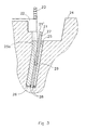
- FIG. 3 shows a second embodiment of a pile 21, which is suitable in particular for carrying out the method according to the invention.
- This pile 21 too is sunk into the ground in order to support an existing object 22 or the like, which in this case in turn supports a wall 23.
- an additional quantity of displaceable material 25a is positioned directly beneath the wall base 22.
- a widened pile base 26, which displaces the ground 24 as the pile 21 is being introduced, is provided at the bottom end of the pile.
- the widened pile base 26 is of asymmetrical design in the device shown in Figure 3 , and is introduced into the ground in such a manner that that section of the pile base 26 which is at the greatest distance from the pile is located on that side of the pile 21 towards which the upper section of the pile 21 is pushed during the sideways movement of the method of the invention.
- One advantage of an asymmetric pile base 26 of this type is that less grout is required, in particular on that side of the pile which is remote from the object. This represents a considerable cost saving.
- Another advantage of an asymmetrical pile base is that the cross-sectional area is smaller, and consequently the pile is subject to less resistance as it is being sunk into the ground, for example by pile-driving.
- a force centre point of a force in the longitudinal direction which is transmitted, for example, to the pile 21 while it is being driven is preferably located outside the longitudinal centre axis of the pile and in the direction of the object.
- the asymmetric widened section of a pile is designed in such a manner that the widened section is short and wide on one side of the pile and long and narrow on an opposite side of the pile, with the short and wide side of the pile being arranged towards and/or beneath the object while the pile is being sunk into the ground.
- the short, wide part and the long, narrow part prefferably be designed in such a way that the moments which are transmitted to the pile by these parts while the pile is being sunk into the ground are substantially equal. This will make it easier for the pile to be sunk into the ground straight, with little likelihood of buckling. Since in this case the moment arm of the long, narrow part is longer, the surface area of this part will be smaller. Consequently, in relative terms less displaceable material is used to fill the space which is cleared above this long, narrow part.
- the widened asymmetric pile base 26 prefferably be designed in such a manner that at least a thin layer of displaceable material, in, particular grout, can be arranged on all sides of the pile.
- the pile 21 it is possible to provide a plurality of passages 27 running in the longitudinal direction of the pile and/or a plurality of discharge openings 28, located around the periphery and in the longitudinal direction, for discharging the displaceable material 25.
- a plurality of passages 27 running in the longitudinal direction of the pile and/or a plurality of discharge openings 28, located around the periphery and in the longitudinal direction, for discharging the displaceable material 25.
- the passages it is also possible to provide one or more lines or hoses which run in the longitudinal direction of the pile 21 inside or along the pile 21 for supplying the displaceable material 25.
- the upper section of the pile 21 can advantageously be pivoted with respect to the lower section, by means of a pivot 29. During the sideways movement of the upper section of the pile 21 towards the position 21' in which the wall base is at least partially supported by the top end of the pile, it is then only necessary for the top section of the pile 21 to be moved through the displaceable material, whereas the lower section can remain in a fixed position with respect to the ground 24.
- the displaceable material 25 will dry out and/or set and thereby fix the pile in place. It is also possible for the pile to be mechanically fixed or for the displaceable material 25 to be replaced with a harder material or a material which does dry out or set sufficiently to fix the pile.
- the pivot 29 is preferably fixed in the position in which the upper section and the lower section of the pile 21 are in line with one another. After the pile 21 has been sunk into the ground, the pivot 29 can be released, so that the upper section of the pile 21 can be pushed through the displaceable material 25 towards the wall base 22 while the lower section of the pile 21 can remain in its original position.
- the pile 21 preferably comprises a cavity which, after the pile has been moved into its end position 21', can be filled with (cement) grout, concrete or the like, so that the upper section and the lower section of the pile 21' are fixed with respect to one another as a result of the (cement) grout, concrete or the like drying out and/or setting. If appropriate, a reinforcement may in this case be provided in the cavity. It is possible for the passage 27 to be used as the cavity for filling the pile, which passage has previously, during the sinking of the pile into the ground 24, been used to supply the displaceable material 25.
- FIG. 4 shows a third embodiment of a pile which is suitable for carrying out a method according to the invention.
- the pile is denoted by reference numeral 31.
- the pile 31 is used to support a new object to be put in place, in this case a machine or the like denoted by M, which object M is being installed in an existing building 32, 33.
- the method according to the invention has the advantage that the pile can be moved into a position beneath the object which is to be put in place from the outside without having to (temporarily) damage part of the existing building.
- the figure shows the pile 31 in its end position.
- the pile has first been sunk into the ground 34 while a suitable displaceable material 35, preferably grout, is arranged around the pile 31.
- a suitable displaceable material 35 preferably grout
- the top end of the pile 31 has been moved sideways, displacing the displaceable material 35.
- the displaceable material 35 has preferably been set and/or dried, so that the pile 31 is fixed in its end position.
- the pile 31 At its bottom end, the pile 31 comprises an asymmetric widened pile base 36, and approximately halfway along its longitudinal direction also comprises an additional widened section 40, which in this case is likewise asymmetrical, the cross-sectional area of this additional widened section 40 being larger than the widened pile base 36 of the pile 31.
- the provision of widened sections of this type which increase in cross section in the direction of the top end of the pile 31, results in a layer of displaceable material 5 next to the pile 31 which increases in size towards the top end of the pile 31 in, in this case one, or more steps, being formed at least on that side of the pile which faces towards the object which is to be supported.
- At least one of the one or more widened sections can advantageously be removed, slid away or folded away. After the pile has been sunk into the ground and if appropriate the displaceable material has been introduced, the widened sections can then be removed, slid away or folded away, so that they do not form any obstacle during the sideways movement of at least the upper section of the pile.
- the widened section can be removed in various ways. For example, it is even possible for the widened section to be removed by chemical means, by exploding it or by dissolving it in the ground water, in which case if appropriate a timer mechanism can be provided to start the process.
- a suitable displaceable material to be introduced into the ground under a high pressure and/or at great speed, so that the displaceable material is also provided at a certain distance from the pile shaft. If the displaceable material then penetrates far enough into the ground, it is possible for the widened section to move through this displaceable material, which has been moved outside the pile, during the sideways movement, without impeding the movement of the pile.
- a method of this nature has the advantage that a spray nozzle for introducing displaceable material does not have to project far from the pile and that the one or more widened sections do not have to be designed such that they can be removed, slid away or folded away.
- the widened section of the pile 31 shown in Figure 4 is designed so that it can be folded away.
- the drawing indicates the folded-away widened section by means of a dashed line and the direction in which it is folded away by means of an arrow.
- the widened section will already be in its folded-away position, since this folding operation takes place before the sideways movement of at least a top end of the pile.
- this displaceable material 35 is supplied, for example, via one or more passages, lines or hoses which run in the longitudinal direction through and/or along the pile 31. Even if there are no additional widened sections, it is advantageous for a number of discharge openings for discharging the displaceable material 35 to be provided in the longitudinal direction of the pile. It is also advantageous to provide two or more openings on the periphery of the pile, in such a manner that displaceable material 35 is discharged in a plurality of directions at a certain height.
- the displaceable material 35 can be supplied to the passage 37 in the pile 11 using a device which is known for this purpose, for example a suitable pump.
Landscapes
- Engineering & Computer Science (AREA)
- Structural Engineering (AREA)
- Life Sciences & Earth Sciences (AREA)
- General Life Sciences & Earth Sciences (AREA)
- Mining & Mineral Resources (AREA)
- Paleontology (AREA)
- Civil Engineering (AREA)
- General Engineering & Computer Science (AREA)
- Piles And Underground Anchors (AREA)
- Die Bonding (AREA)
- Adhesives Or Adhesive Processes (AREA)
- Placing Or Removing Of Piles Or Sheet Piles, Or Accessories Thereof (AREA)
- Transition And Organic Metals Composition Catalysts For Addition Polymerization (AREA)
- Disintegrating Or Milling (AREA)
- Pyrane Compounds (AREA)
Claims (46)
- Procédé pour supporter un objet, en particulier un objet existant, dans lequel un pieu est enfoncé dans le sol et est utilisé pour supporter l'objet, caractérisé en ce que le procédé comprend les étapes suivantes consistant à :prévoir du matériau déplaçable autour ou à proximité du pieu avant, pendant et/ou après l'enfoncement du pieu dans le sol,déplacer une section supérieure du pieu latéralement, moyennant quoi le matériau déplaçable est déplacé, etfixer le pieu.
- Procédé selon la revendication 1, caractérisé en ce que la section supérieure du pieu est déplacée latéralement jusqu'à ce qu'une extrémité supérieure du pieu soit positionnée au moins partiellement à l'intérieur ou bien au-dessous de l'objet qui doit être supporté ou bien au-dessous d'une position dans laquelle l'objet à supporter est placé.
- Procédé selon la revendication 1 ou 2, caractérisé en ce que l'objet est une construction existante.
- Procédé selon une ou plusieurs des revendications 1 à 3, caractérisé en ce que le pieu est fixé en permettant au matériau déplaçable de sécher et/ou de durcir.
- Procédé selon une ou plusieurs des revendications 1 à 4, caractérisé en ce que le matériau déplaçable est du ciment qui est introduit de préférence alors que le pieu est enfoncé dans le sol.
- Procédé selon une ou plusieurs des revendications 1 à 5, caractérisé en ce que le pieu est enfoncé dans le sol de manière oblique, de sorte qu'une extrémité inférieure du pieu, après qu'il a été introduit, est positionnée au-dessous de l'objet qui doit être supporté, de sorte que le pieu, après que sa section supérieure a été déplacée latéralement, est dans une position sensiblement verticale.
- Procédé selon une ou plusieurs des revendications 1 à 6, caractérisé en ce que l'on prévoit plus de matériau déplaçable vers la surface du sol.
- Procédé selon une ou plusieurs des revendications 1 à 7, caractérisé en ce qu'une quantité supplémentaire de matériau déplaçable est placée au moins partiellement au-dessous de l'objet qui doit être supporté ou bien au-dessous de la position de l'objet qui doit être mis en place, de sorte que la section supérieure du pieu peut facilement être déplacée dans sa position dans laquelle il doit être fixé.
- Procédé selon une ou plusieurs des revendications 1 à 8, caractérisé en ce que le pieu, par exemple au niveau de son extrémité inférieure, est prévu avec une section élargie qui a une surface transversale plus grande que le pieu.
- Procédé selon une ou plusieurs des revendications 1 à 9, caractérisé en ce que le pieu est prévu, sur sa longueur, avec deux sections élargies ou plus, dont la surface transversale augmente vers l'extrémité supérieure du pieu.
- Procédé selon la revendication 9 ou 10, caractérisé en ce qu'au moins l'une des une ou plusieurs sections élargies peut être retirée, éloignée par coulissement ou repliée.
- Procédé selon une ou plusieurs des revendications 9 à 11, caractérisé en ce que la section élargie ou les sections élargies est / sont asymétrique(s).
- Procédé selon la revendication 12, caractérisé en ce que la section élargie ou les sections élargies est / sont courte(s) et large(s) sur un côté du pieu et longue(s) et étroite(s) sur un côté opposé du pieu, avec le côté court et large du pieu qui est agencé afin de faire face et/ou se trouver au-dessous de l'objet lorsque le pieu est enfoncé dans le sol.
- Procédé selon une ou plusieurs des revendications 9 à 13, caractérisé en ce que l'on utilise un élément de support qui, alors que le pieu est enfoncé dans le sol, renforce le pieu et la (les) sections(s) élargie(s), lequel élément de support s'étend sur une partie de la longueur du pieu et a une section transversale qui augmente du point de vue de la taille dans la direction de l'extrémité inférieure du pieu.
- Procédé selon la revendication 14, caractérisé en ce que l'élément de support, dans la direction longitudinale du pieu, est composé d'un certain nombre de segments qui peuvent être montés en succession lorsque le pieu est enfoncé dans le sol.
- Procédé selon une ou plusieurs des revendications 1 à 15, caractérisé en ce que l'opération consistant à enfoncer le pieu dans le sol est réalisée de sorte qu'un point central de force d'une force dans la direction longitudinale qui est transmise au pieu lorsque le pieu est enfoncé dans le sol, se trouve à l'extérieur de l'axe longitudinal du pieu, dans la direction de l'objet.
- Procédé selon une ou plusieurs des revendications 1 à 16, caractérisé en ce que le pieu est prévu avec au moins un passage, une conduite, un tuyau flexible ou similaire, qui s'étend dans la direction longitudinale du pieu, s'ouvre au niveau d'un ou de plusieurs emplacements sur la périphérie externe du pieu et est approprié pour décharger le matériau déplaçable, en particulier, du ciment, au niveau de ces emplacements.
- Procédé selon revendication 17, caractérisé en ce que le passage, la conduite, le tuyau flexible ou similaire s'ouvre au moins à proximité d'une extrémité inférieure du pieu.
- Procédé selon une ou plusieurs des revendications 1 à 18, caractérisé en ce que le pieu comprend un pivot, il est ainsi possible pour la section supérieure du pieu de pivoter par rapport à une section restante du pieu.
- Procédé selon la revendication 19, caractérisé en ce que le pivot peut être fixe, de préférence au moins lorsque les sections supérieure et restante du pieu sont alignées l'une par rapport à l'autre.
- Procédé selon une ou plusieurs des revendications 1 à 20, caractérisé en ce que le pieu est tubulaire, en particulier une section en caisson.
- Procédé selon une ou plusieurs des revendications 1 à 21, caractérisé en ce que le pieu a une section en forme de H ou une section en forme de I.
- Procédé selon une ou plusieurs des revendications 1 à 22, caractérisé en ce que le pieu comprend une cavité qui s'étend dans la direction longitudinale du pieu sur une partie considérable de celui-ci.
- Procédé selon une ou plusieurs des revendications 1 à 23, caractérisé en ce que le pieu est positionné sensiblement verticalement après qu'il a été enfoncé.
- Procédé selon une ou plusieurs des revendications 1 à 24, caractérisé en ce que le pieu est sous une charge sensiblement verticale après qu'il a été enfoncé.
- Pieu à enfoncer dans le sol qui est particulièrement approprié pour réaliser un procédé selon une ou plusieurs des revendications 1 à 25.
- Pieu selon la revendication 26, caractérisé en ce que le pieu est prévu, par exemple au niveau de son extrémité inférieure, avec une section élargie qui a une surface transversale plus grande que le pieu.
- Pieu selon une ou plusieurs des revendications 26 ou 27, caractérisé en ce que le pieu est prévu sur sa longueur avec deux sections élargies ou plus, dont la surface transversale augmente vers l'extrémité supérieure du pieu.
- Pieu selon la revendication 28, caractérisé en ce qu'au moins l'un des une ou plusieurs des sections élargies peut être retirée, éloignée par coulissement ou repliée.
- Pieu selon une ou plusieurs des revendications 27 à 29, caractérisé en ce que la section élargie ou les sections élargies est / sont asymétrique(s).
- Pieu selon la revendication 30, caractérisé en ce que la section élargie ou bien les sections élargies est / sont courte(s) et large(s) sur un côté du pieu et longue(s) et étroite(s) sur un côté opposé, avec le côté court et large du pieu qui est agencé afin de faire face et/ou être au-dessous de l'objet lorsque le pieu est enfoncé dans le sol.
- Pieu selon une ou plusieurs des revendications 27 à 31, caractérisé en ce que le pieu comprend un élément de support qui, alors que le pieu est enfoncé dans le sol, renforce le pieu et la (les) section(s) élargie(s), lequel élément de support s'étend sur une partie de la longueur du pieu et augmente en section transversale dans la direction de l'extrémité inférieure du pieu.
- Pieu selon la revendication 32, caractérisé en ce que l'élément de support, dans la direction longitudinale du pieu, est composé d'un certain nombre de segments qui peuvent être montés en succession lorsque le pieu est enfoncé dans le sol.
- Pieu selon une ou plusieurs des revendications 26 à 33, caractérisé en ce que le pieu est prévu avec au moins un passage, une conduite, un tuyau flexible ou similaire qui s'étend dans la direction longitudinale du pieu, s'ouvre au niveau d'un ou plusieurs emplacements sur la périphérie externe du pieu et est approprié pour décharger le matériau déplaçable, en particulier du ciment, au niveau de ces emplacements.
- Pieu selon la revendication 34, caractérisé en ce que le passage, la conduite, le tuyau flexible ou similaire s'ouvre au moins à proximité d'une extrémité inférieure du pieu.
- Pieu selon une ou plusieurs des revendications 26 à 35, caractérisé en ce que le pieu comprend un pivot, il est ainsi possible pour la section supérieure du pieu de pivoter par rapport à une section restante du pieu.
- Pieu selon la revendication 36, caractérisé en ce que le pivot peut être fixe, de préférence au moins lorsque la section supérieure et la section restante du pieu sont alignées l'une par rapport à l'autre.
- Pieu selon une ou plusieurs des revendications 26 à 37, caractérisé en ce que le pieu est tubulaire, en particulier une section en caisson.
- Pieu selon une ou plusieurs des revendications 26 à 38, caractérisé en ce que le pieu a une section en forme de H ou bien une section en forme de I.
- Pieu selon une ou plusieurs des revendications 26 à 39, caractérisé en ce que le pieu comprend une cavité qui s'étend dans la direction longitudinale du pieu sur une partie considérable de celui-ci.
- Pieu selon une ou plusieurs des revendications 26 à 40, caractérisé en ce que le pieu est réalisé à partir de métal.
- Pieu selon une ou plusieurs des revendications 26 à 40, caractérisé en ce que le pieu est réalisé à partir d'acier.
- Pieu selon une ou plusieurs des revendications 26 à 40, caractérisé en ce que le pieu est réalisé à partir de béton armé.
- Pieu selon une ou plusieurs des revendications 26 à 40, caractérisé en ce que le pieu est réalisé à partir de plastique.
- Pieu selon une ou plusieurs des revendications 26 à 44, caractérisé en ce que le pieu est une section de file de palplanches.
- Pieu selon une ou plusieurs des revendications 26 à 45, caractérisé en ce que le pieu est composé de deux pieux séparés et/ou de sections de file de palplanches ou plus.
Applications Claiming Priority (3)
| Application Number | Priority Date | Filing Date | Title |
|---|---|---|---|
| NL1021975A NL1021975C2 (nl) | 2002-11-22 | 2002-11-22 | Werkwijze voor het ondersteunen van een object, in het bijzonder een bestaand object. |
| NL1021975 | 2002-11-22 | ||
| PCT/NL2003/000810 WO2004048703A1 (fr) | 2002-11-22 | 2003-11-18 | Procede destine a supporter un objet, en particulier un objet deja en place |
Publications (2)
| Publication Number | Publication Date |
|---|---|
| EP1579080A1 EP1579080A1 (fr) | 2005-09-28 |
| EP1579080B1 true EP1579080B1 (fr) | 2010-01-06 |
Family
ID=32389636
Family Applications (1)
| Application Number | Title | Priority Date | Filing Date |
|---|---|---|---|
| EP03774388A Expired - Lifetime EP1579080B1 (fr) | 2002-11-22 | 2003-11-18 | Procede destine a supporter un objet, en particulier un objet deja en place |
Country Status (6)
| Country | Link |
|---|---|
| EP (1) | EP1579080B1 (fr) |
| AT (1) | ATE454501T1 (fr) |
| AU (1) | AU2003282627A1 (fr) |
| DE (1) | DE60330911D1 (fr) |
| NL (1) | NL1021975C2 (fr) |
| WO (1) | WO2004048703A1 (fr) |
Families Citing this family (1)
| Publication number | Priority date | Publication date | Assignee | Title |
|---|---|---|---|---|
| CN110700238B (zh) * | 2019-10-08 | 2024-05-28 | 上海建工一建集团有限公司 | 既有地下室扩建的新建围护结构及其施工方法 |
Family Cites Families (1)
| Publication number | Priority date | Publication date | Assignee | Title |
|---|---|---|---|---|
| DE2710456A1 (de) * | 1977-03-10 | 1978-09-14 | Brechtel Johannes | Abstuetzvorrichtung zum unterfangen einer auf einem grund stehenden mauer |
-
2002
- 2002-11-22 NL NL1021975A patent/NL1021975C2/nl not_active IP Right Cessation
-
2003
- 2003-11-18 AT AT03774388T patent/ATE454501T1/de not_active IP Right Cessation
- 2003-11-18 EP EP03774388A patent/EP1579080B1/fr not_active Expired - Lifetime
- 2003-11-18 AU AU2003282627A patent/AU2003282627A1/en not_active Abandoned
- 2003-11-18 DE DE60330911T patent/DE60330911D1/de not_active Expired - Lifetime
- 2003-11-18 WO PCT/NL2003/000810 patent/WO2004048703A1/fr not_active Ceased
Also Published As
| Publication number | Publication date |
|---|---|
| EP1579080A1 (fr) | 2005-09-28 |
| AU2003282627A1 (en) | 2004-06-18 |
| WO2004048703A1 (fr) | 2004-06-10 |
| ATE454501T1 (de) | 2010-01-15 |
| DE60330911D1 (de) | 2010-02-25 |
| NL1021975C2 (nl) | 2004-05-26 |
Similar Documents
| Publication | Publication Date | Title |
|---|---|---|
| EP0032132B1 (fr) | Erection d'une construction sur pieux | |
| US7416367B2 (en) | Lateral force resistance device | |
| US20220098817A1 (en) | Method for constructing structure | |
| CN102071693B (zh) | 变截面水泥土重力式挡墙的施工方法 | |
| JP2012107479A (ja) | 地下・地上構造物の施工方法 | |
| CN100999900A (zh) | 一种底部撞击式钢管混凝土桩及其施工方法 | |
| JP3126896B2 (ja) | 不等沈下構築物の復元工法 | |
| EP1579080B1 (fr) | Procede destine a supporter un objet, en particulier un objet deja en place | |
| US20240200299A1 (en) | Hook, Hook Pile Foundation System and its Application Thereof | |
| JP2002188157A (ja) | 既設構造物基礎の耐震補強工法 | |
| KR101765879B1 (ko) | 지반보강용 합성블록체 및 이를 이용한 기초저면의 보강공법 | |
| KR20170080051A (ko) | 조류발전 지지구조 시스템 | |
| JP2004131923A (ja) | 地中既設構造物の引抜工法 | |
| JPH0776845A (ja) | オープンケーソンの沈設方法 | |
| KR101257905B1 (ko) | 매입말뚝을 이용한 기초 공법 | |
| JP2007211408A (ja) | 既設コンクリート橋脚の耐震補強工法 | |
| KR100531023B1 (ko) | 건축기초용 앵커의 설치방법 | |
| KR101040042B1 (ko) | 가변형 굴착 비트를 이용한 파일 시공 방법 | |
| CN114657987B (zh) | 水泥土桩无震感插入钢管的施工方法 | |
| EP1348812A1 (fr) | Méthodes et dispositif de construction | |
| CN112302031A (zh) | 用于倾斜建筑物的加固纠偏体系和方法 | |
| JP7790936B2 (ja) | 地下構造物の構築方法 | |
| KR102113117B1 (ko) | 가이드월을 이용한 구조물 시공방법 | |
| KR101361842B1 (ko) | 경사파일 시공장치 및 이를 이용한 경사파일 시공방법 | |
| KR102904616B1 (ko) | 흙막이 벽체의 토사 공급용 버킷장치 |
Legal Events
| Date | Code | Title | Description |
|---|---|---|---|
| PUAI | Public reference made under article 153(3) epc to a published international application that has entered the european phase |
Free format text: ORIGINAL CODE: 0009012 |
|
| 17P | Request for examination filed |
Effective date: 20050622 |
|
| AK | Designated contracting states |
Kind code of ref document: A1 Designated state(s): AT BE BG CH CY CZ DE DK EE ES FI FR GB GR HU IE IT LI LU MC NL PT RO SE SI SK TR |
|
| AX | Request for extension of the european patent |
Extension state: AL LT LV MK |
|
| DAX | Request for extension of the european patent (deleted) | ||
| GRAP | Despatch of communication of intention to grant a patent |
Free format text: ORIGINAL CODE: EPIDOSNIGR1 |
|
| GRAS | Grant fee paid |
Free format text: ORIGINAL CODE: EPIDOSNIGR3 |
|
| GRAA | (expected) grant |
Free format text: ORIGINAL CODE: 0009210 |
|
| AK | Designated contracting states |
Kind code of ref document: B1 Designated state(s): AT BE BG CH CY CZ DE DK EE ES FI FR GB GR HU IE IT LI LU MC NL PT RO SE SI SK TR |
|
| REG | Reference to a national code |
Ref country code: GB Ref legal event code: FG4D |
|
| REG | Reference to a national code |
Ref country code: CH Ref legal event code: EP |
|
| REG | Reference to a national code |
Ref country code: IE Ref legal event code: FG4D |
|
| REF | Corresponds to: |
Ref document number: 60330911 Country of ref document: DE Date of ref document: 20100225 Kind code of ref document: P |
|
| REG | Reference to a national code |
Ref country code: NL Ref legal event code: T3 |
|
| PG25 | Lapsed in a contracting state [announced via postgrant information from national office to epo] |
Ref country code: SI Free format text: LAPSE BECAUSE OF FAILURE TO SUBMIT A TRANSLATION OF THE DESCRIPTION OR TO PAY THE FEE WITHIN THE PRESCRIBED TIME-LIMIT Effective date: 20100106 |
|
| REG | Reference to a national code |
Ref country code: CH Ref legal event code: NV Representative=s name: SAEGER & PARTNER PATENT- UND RECHTSANWAELTE |
|
| PG25 | Lapsed in a contracting state [announced via postgrant information from national office to epo] |
Ref country code: AT Free format text: LAPSE BECAUSE OF FAILURE TO SUBMIT A TRANSLATION OF THE DESCRIPTION OR TO PAY THE FEE WITHIN THE PRESCRIBED TIME-LIMIT Effective date: 20100106 |
|
| PG25 | Lapsed in a contracting state [announced via postgrant information from national office to epo] |
Ref country code: PT Free format text: LAPSE BECAUSE OF FAILURE TO SUBMIT A TRANSLATION OF THE DESCRIPTION OR TO PAY THE FEE WITHIN THE PRESCRIBED TIME-LIMIT Effective date: 20100506 Ref country code: ES Free format text: LAPSE BECAUSE OF FAILURE TO SUBMIT A TRANSLATION OF THE DESCRIPTION OR TO PAY THE FEE WITHIN THE PRESCRIBED TIME-LIMIT Effective date: 20100417 |
|
| PG25 | Lapsed in a contracting state [announced via postgrant information from national office to epo] |
Ref country code: FI Free format text: LAPSE BECAUSE OF FAILURE TO SUBMIT A TRANSLATION OF THE DESCRIPTION OR TO PAY THE FEE WITHIN THE PRESCRIBED TIME-LIMIT Effective date: 20100106 |
|
| PG25 | Lapsed in a contracting state [announced via postgrant information from national office to epo] |
Ref country code: RO Free format text: LAPSE BECAUSE OF FAILURE TO SUBMIT A TRANSLATION OF THE DESCRIPTION OR TO PAY THE FEE WITHIN THE PRESCRIBED TIME-LIMIT Effective date: 20100106 Ref country code: SE Free format text: LAPSE BECAUSE OF FAILURE TO SUBMIT A TRANSLATION OF THE DESCRIPTION OR TO PAY THE FEE WITHIN THE PRESCRIBED TIME-LIMIT Effective date: 20100106 Ref country code: GR Free format text: LAPSE BECAUSE OF FAILURE TO SUBMIT A TRANSLATION OF THE DESCRIPTION OR TO PAY THE FEE WITHIN THE PRESCRIBED TIME-LIMIT Effective date: 20100407 Ref country code: EE Free format text: LAPSE BECAUSE OF FAILURE TO SUBMIT A TRANSLATION OF THE DESCRIPTION OR TO PAY THE FEE WITHIN THE PRESCRIBED TIME-LIMIT Effective date: 20100106 Ref country code: CY Free format text: LAPSE BECAUSE OF FAILURE TO SUBMIT A TRANSLATION OF THE DESCRIPTION OR TO PAY THE FEE WITHIN THE PRESCRIBED TIME-LIMIT Effective date: 20100106 |
|
| PLBE | No opposition filed within time limit |
Free format text: ORIGINAL CODE: 0009261 |
|
| STAA | Information on the status of an ep patent application or granted ep patent |
Free format text: STATUS: NO OPPOSITION FILED WITHIN TIME LIMIT |
|
| PG25 | Lapsed in a contracting state [announced via postgrant information from national office to epo] |
Ref country code: CZ Free format text: LAPSE BECAUSE OF FAILURE TO SUBMIT A TRANSLATION OF THE DESCRIPTION OR TO PAY THE FEE WITHIN THE PRESCRIBED TIME-LIMIT Effective date: 20100106 Ref country code: BG Free format text: LAPSE BECAUSE OF FAILURE TO SUBMIT A TRANSLATION OF THE DESCRIPTION OR TO PAY THE FEE WITHIN THE PRESCRIBED TIME-LIMIT Effective date: 20100406 Ref country code: SK Free format text: LAPSE BECAUSE OF FAILURE TO SUBMIT A TRANSLATION OF THE DESCRIPTION OR TO PAY THE FEE WITHIN THE PRESCRIBED TIME-LIMIT Effective date: 20100106 |
|
| 26N | No opposition filed |
Effective date: 20101007 |
|
| PG25 | Lapsed in a contracting state [announced via postgrant information from national office to epo] |
Ref country code: DK Free format text: LAPSE BECAUSE OF FAILURE TO SUBMIT A TRANSLATION OF THE DESCRIPTION OR TO PAY THE FEE WITHIN THE PRESCRIBED TIME-LIMIT Effective date: 20100106 |
|
| PG25 | Lapsed in a contracting state [announced via postgrant information from national office to epo] |
Ref country code: IT Free format text: LAPSE BECAUSE OF FAILURE TO SUBMIT A TRANSLATION OF THE DESCRIPTION OR TO PAY THE FEE WITHIN THE PRESCRIBED TIME-LIMIT Effective date: 20100106 |
|
| PG25 | Lapsed in a contracting state [announced via postgrant information from national office to epo] |
Ref country code: MC Free format text: LAPSE BECAUSE OF NON-PAYMENT OF DUE FEES Effective date: 20101130 |
|
| PG25 | Lapsed in a contracting state [announced via postgrant information from national office to epo] |
Ref country code: IE Free format text: LAPSE BECAUSE OF NON-PAYMENT OF DUE FEES Effective date: 20101118 |
|
| PG25 | Lapsed in a contracting state [announced via postgrant information from national office to epo] |
Ref country code: HU Free format text: LAPSE BECAUSE OF FAILURE TO SUBMIT A TRANSLATION OF THE DESCRIPTION OR TO PAY THE FEE WITHIN THE PRESCRIBED TIME-LIMIT Effective date: 20100707 Ref country code: LU Free format text: LAPSE BECAUSE OF NON-PAYMENT OF DUE FEES Effective date: 20101118 |
|
| PG25 | Lapsed in a contracting state [announced via postgrant information from national office to epo] |
Ref country code: TR Free format text: LAPSE BECAUSE OF FAILURE TO SUBMIT A TRANSLATION OF THE DESCRIPTION OR TO PAY THE FEE WITHIN THE PRESCRIBED TIME-LIMIT Effective date: 20100106 |
|
| PGFP | Annual fee paid to national office [announced via postgrant information from national office to epo] |
Ref country code: DE Payment date: 20121123 Year of fee payment: 10 Ref country code: CH Payment date: 20121123 Year of fee payment: 10 Ref country code: FR Payment date: 20121211 Year of fee payment: 10 |
|
| PGFP | Annual fee paid to national office [announced via postgrant information from national office to epo] |
Ref country code: BE Payment date: 20121128 Year of fee payment: 10 Ref country code: GB Payment date: 20121030 Year of fee payment: 10 |
|
| REG | Reference to a national code |
Ref country code: CH Ref legal event code: PCAR Free format text: NEW ADDRESS: FELDGUEETLIWEG 130, 8706 MEILEN (CH) |
|
| BERE | Be: lapsed |
Owner name: DE WAAL TECHNOLOGY & CONSULTANCY B.V. Effective date: 20131130 |
|
| REG | Reference to a national code |
Ref country code: CH Ref legal event code: PL |
|
| GBPC | Gb: european patent ceased through non-payment of renewal fee |
Effective date: 20131118 |
|
| PG25 | Lapsed in a contracting state [announced via postgrant information from national office to epo] |
Ref country code: CH Free format text: LAPSE BECAUSE OF NON-PAYMENT OF DUE FEES Effective date: 20131130 Ref country code: LI Free format text: LAPSE BECAUSE OF NON-PAYMENT OF DUE FEES Effective date: 20131130 |
|
| REG | Reference to a national code |
Ref country code: FR Ref legal event code: ST Effective date: 20140731 |
|
| PG25 | Lapsed in a contracting state [announced via postgrant information from national office to epo] |
Ref country code: DE Free format text: LAPSE BECAUSE OF NON-PAYMENT OF DUE FEES Effective date: 20140603 |
|
| PGFP | Annual fee paid to national office [announced via postgrant information from national office to epo] |
Ref country code: NL Payment date: 20140528 Year of fee payment: 11 |
|
| REG | Reference to a national code |
Ref country code: DE Ref legal event code: R119 Ref document number: 60330911 Country of ref document: DE Effective date: 20140603 |
|
| PG25 | Lapsed in a contracting state [announced via postgrant information from national office to epo] |
Ref country code: BE Free format text: LAPSE BECAUSE OF NON-PAYMENT OF DUE FEES Effective date: 20131130 |
|
| PG25 | Lapsed in a contracting state [announced via postgrant information from national office to epo] |
Ref country code: FR Free format text: LAPSE BECAUSE OF NON-PAYMENT OF DUE FEES Effective date: 20131202 Ref country code: GB Free format text: LAPSE BECAUSE OF NON-PAYMENT OF DUE FEES Effective date: 20131118 |
|
| REG | Reference to a national code |
Ref country code: NL Ref legal event code: V1 Effective date: 20150601 |
|
| PG25 | Lapsed in a contracting state [announced via postgrant information from national office to epo] |
Ref country code: NL Free format text: LAPSE BECAUSE OF NON-PAYMENT OF DUE FEES Effective date: 20150601 |