EP1579120B1 - Support compliant pour palier de butee axiale a capacite de charge accrue - Google Patents
Support compliant pour palier de butee axiale a capacite de charge accrue Download PDFInfo
- Publication number
- EP1579120B1 EP1579120B1 EP03813054A EP03813054A EP1579120B1 EP 1579120 B1 EP1579120 B1 EP 1579120B1 EP 03813054 A EP03813054 A EP 03813054A EP 03813054 A EP03813054 A EP 03813054A EP 1579120 B1 EP1579120 B1 EP 1579120B1
- Authority
- EP
- European Patent Office
- Prior art keywords
- compliant
- air
- compliant support
- support according
- ring
- Prior art date
- Legal status (The legal status is an assumption and is not a legal conclusion. Google has not performed a legal analysis and makes no representation as to the accuracy of the status listed.)
- Expired - Lifetime
Links
- 239000011888 foil Substances 0.000 claims description 35
- NBVXSUQYWXRMNV-UHFFFAOYSA-N fluoromethane Chemical compound FC NBVXSUQYWXRMNV-UHFFFAOYSA-N 0.000 claims description 4
- ZHPNWZCWUUJAJC-UHFFFAOYSA-N fluorosilicon Chemical compound [Si]F ZHPNWZCWUUJAJC-UHFFFAOYSA-N 0.000 claims description 4
- 238000004891 communication Methods 0.000 claims description 3
- 230000007423 decrease Effects 0.000 claims description 2
- 238000013016 damping Methods 0.000 description 5
- 230000003466 anti-cipated effect Effects 0.000 description 1
- 239000002826 coolant Substances 0.000 description 1
- 238000001914 filtration Methods 0.000 description 1
- 239000012530 fluid Substances 0.000 description 1
- 239000000314 lubricant Substances 0.000 description 1
- 238000012423 maintenance Methods 0.000 description 1
- 238000004519 manufacturing process Methods 0.000 description 1
- 239000000463 material Substances 0.000 description 1
- 238000012545 processing Methods 0.000 description 1
- 238000012552 review Methods 0.000 description 1
Images


Classifications
-
- F—MECHANICAL ENGINEERING; LIGHTING; HEATING; WEAPONS; BLASTING
- F16—ENGINEERING ELEMENTS AND UNITS; GENERAL MEASURES FOR PRODUCING AND MAINTAINING EFFECTIVE FUNCTIONING OF MACHINES OR INSTALLATIONS; THERMAL INSULATION IN GENERAL
- F16C—SHAFTS; FLEXIBLE SHAFTS; ELEMENTS OR CRANKSHAFT MECHANISMS; ROTARY BODIES OTHER THAN GEARING ELEMENTS; BEARINGS
- F16C17/00—Sliding-contact bearings for exclusively rotary movement
- F16C17/04—Sliding-contact bearings for exclusively rotary movement for axial load only
- F16C17/042—Sliding-contact bearings for exclusively rotary movement for axial load only with flexible leaves to create hydrodynamic wedge, e.g. axial foil bearings
-
- F—MECHANICAL ENGINEERING; LIGHTING; HEATING; WEAPONS; BLASTING
- F16—ENGINEERING ELEMENTS AND UNITS; GENERAL MEASURES FOR PRODUCING AND MAINTAINING EFFECTIVE FUNCTIONING OF MACHINES OR INSTALLATIONS; THERMAL INSULATION IN GENERAL
- F16C—SHAFTS; FLEXIBLE SHAFTS; ELEMENTS OR CRANKSHAFT MECHANISMS; ROTARY BODIES OTHER THAN GEARING ELEMENTS; BEARINGS
- F16C27/00—Elastic or yielding bearings or bearing supports, for exclusively rotary movement
- F16C27/06—Elastic or yielding bearings or bearing supports, for exclusively rotary movement by means of parts of rubber or like materials
- F16C27/063—Sliding contact bearings
-
- F—MECHANICAL ENGINEERING; LIGHTING; HEATING; WEAPONS; BLASTING
- F16—ENGINEERING ELEMENTS AND UNITS; GENERAL MEASURES FOR PRODUCING AND MAINTAINING EFFECTIVE FUNCTIONING OF MACHINES OR INSTALLATIONS; THERMAL INSULATION IN GENERAL
- F16C—SHAFTS; FLEXIBLE SHAFTS; ELEMENTS OR CRANKSHAFT MECHANISMS; ROTARY BODIES OTHER THAN GEARING ELEMENTS; BEARINGS
- F16C2360/00—Engines or pumps
Definitions
- the invention relates to a compliant support for an axial thrust air bearing.
- Air bearings or foil bearings have been used in high speed turbo machinery, motors, turbochargers, or fluid processing machines which take advantage of their inherent advantages with a flow of compressed air used as a lubricant and coolant.
- Oil lubricated bearings impose a much higher cost and maintenance load as well as reliability problems associated with oil leakage, filtering and conduits.
- U.S. Patent No. 6,286,303 discloses air foil bearings for a gas turbine engine including radial air foil bearings and axial thrust air foil bearings.
- the permissible tolerance for relatively large diameter air foil bearings, especially axial thrust bearings is less than optimum regarding misalignment, parallelism, squareness and waviness of the running surface as well as load capacity and damping capacity during engine surges.
- Another complient support for an axial thrust air foil bearing between a shaft and a housing with the features of the first part of claim 1 is known from US 4 776 077 A .
- the housing has a housing bearing surface and an air inlet in communication with a source of pressurized air.
- An annular foil support sleeve is disposed on the housing bearing surface, having an air foil surface with an array of foils. The foils serve to conduct air from the air inlet forming a pressurized air curtain between the runner bearing surface and foils on the sleeve and is then disposed of through an air outlet.
- the sleeve has a compliant surface with at least one compliant annular ring.
- the compliant surface includes at least one compliant annular ring such as a fluorocarbon O-ring for low temperature service under 300°F; a fluorosilicon O-ring for mid-range temperature service 300-600°F; or a metallic mesh ring for high temperature service over 600°-F.
- a compliant annular ring such as a fluorocarbon O-ring for low temperature service under 300°F; a fluorosilicon O-ring for mid-range temperature service 300-600°F; or a metallic mesh ring for high temperature service over 600°-F.
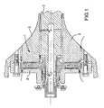
- Figure 1 is an axial cross-sectional view of an axial thrust air foil bearing with compliant support in accordance with the invention disposed on two sides of a rotary flange extending radially from a shaft into a bearing housing with compressed air flow indicated with arrows.
- Figure 2 is a detailed axial sectional view showing the details of the sleeve and rotary flange with air flow over foils.
- Figure 3 is a radial sectional view along line 3-3 of Figure 2, showing the compliant rings within the compliant surface of the sleeve.
- Figure 4 is a radial sectional view along line 4-4 of Figure 2, showing the foils within the rotary flange facing surface of the sleeve.
- Axial thrust bearing 1 bears the axial loads imposed by engine operation on the shaft 2. Rapid fluctuations in axial load caused by engine surges for example, are accommodated as explained below.
- Figure 1 shows an axial cross-sectional view through an air foil axial thrust bearing 1 in accordance with the invention.
- the axial thrust air bearing 1 transfers axial loads between the shaft 2 and the bearing housing 3.
- An annular thrust runner flange 4 extends radially from the shaft 2 and in the embodiment shown has a forward runner bearing surface 5 and a rearward runner bearing surface 6.
- the housing 3 also has a forward housing bearing surface 7 and a rearward housing bearing surface 8.
- Air inlets 9 are in communication with the source of air such as the compressor ducted from an air bleed (not shown). Air from the inlets 9 is conducted over a plurality of foils 10 which in the embodiment shown are located on the air foil surface of each sleeve 13 facing the abutting surfaces 5, 6 of the flange 4.
- the foils 10 create a cushion of air flowing between the adjacent bearing surfaces.
- the foils 10 are formed as circumferentially spaced apart axially protruding planar surfaces with radially extending air channels 16 between adjacent foils 10. The cross-section of the channels 16 decreases as the air flows downstream.
- the airfoils 10 are positioned on the runner side of the sleeves 13 to create a compressed air curtain that serves to lubricate the boundary between engaging surfaces. A curtain of air is conducted from the inlets 9 over the air foils 10 between the runner bearing surfaces 5, 6 and the facing sleeve surfaces to the outlets 11 as indicated by arrows in Figure 2.
- a sleeve 13 with compliant annular rings 12 is positioned between opposing surfaces of the flange 4 and bearing housing 3 providing the advantages that load capacity is increased and damping of axial loading during engine surges is improved. In addition, tolerances are increased to accommodate misalignment between components, parallelism, errors in squareness and waviness of the bearing surfaces 5-8.
- the sleeve 13 includes the air foils 10 with minimal gap between the opposing surfaces.
- the sleeve 13 has a foil surface 14 and a compliant surface 15.
- the compliant surface 15 and the bearing housing surfaces 7, 8 include annular grooves for housing two coaxial compliant annular rings 12.
- Figure 3 shows the rings 12 mounted in the grooves of the sleeve 13.
- the compliant annular rings 12 may be utilized for the compliant annular rings 12 however in all cases the compliant rings 12 should retain a high degree of elasticity to accommodate the necessary load damping or load bearing while maintaining sufficient clearance between the air foils 10 and runner bearing surfaces 5, 6 for proper operation of the air foil bearing.
- fluorocarbon O-ring is proposed as a compliant ring 12.
- operating temperatures are between 300 °F and 600 °F (149°C and 298°C)
- a fluorosilicon O-ring can be used as a compliant ring 12 and where operating temperatures are in excess of 600 oF (298°C), a heat resistant metallic mesh ring 12 is anticipated.
- the compliant support includes two annular foil support sleeves 13. However depending on the load capacity, and loading direction, a single sleeve 13 or multiple sleeves 13 may be utilized. Further, in the embodiment shown the inlets 9 are disposed radially outwardly from the flange 4 and the air outlets 11 are disposed adjacent to a radially inward portion of the flange 4 close to the shaft 2. However it will be apparent that depending on availability of compressed air, air flow may be reversed, i.e. flowing radially outwardly as opposed to radially inwardly as shown in Figure 2.
Landscapes
- Engineering & Computer Science (AREA)
- General Engineering & Computer Science (AREA)
- Mechanical Engineering (AREA)
- Physics & Mathematics (AREA)
- Fluid Mechanics (AREA)
- Support Of The Bearing (AREA)
- Sliding-Contact Bearings (AREA)
- Structures Of Non-Positive Displacement Pumps (AREA)
- Mounting Of Bearings Or Others (AREA)
Claims (12)
- Support conforme pour un palier à air (1) à poussée axiale entre un arbre (2) et un boîtier (3), une roue (4) de poussée annulaire s'étendant radialement à partir de l'arbre (2) ayant une surface de palier de roue (5, 6), le boîtier ayant une surface de palier de boîtier (7, 8) et une entrée d'air (9) en communication avec une source d'air sous-pression, le support conforme comprenant : un manchon de support de déflecteur annulaire (13), disposé sur la surface de palier du boîtier (7, 8), comprenant des moyens de déflecteur d'air, sur une surface de déflecteur d'air (5, 6), comprenant une pluralité de déflecteurs (10), pour conduire l'air de l'entrée (9) dans un rideau d'air sous-pression entre la surface de palier de roue (5, 6) et le manchon (13) jusqu'à une sortie (11), caractérisé en ce que :le manchon (13) ayant une surface conforme (15) avec au moins un joint torique conforme (12) ou au moins une bague en maille métallique (12).
- Support conforme selon la revendication 1, dans lequel la surface conforme (15) comprend deux joints toriques conformes coaxiaux (12) ou deux bagues en maille métallique (12).
- Support conforme selon la revendication 1 ou 2, dans lequel le ou chaque joint torique conforme (12) est choisi dans le groupe comprenant : un joint torique fluorocarboné (12) ; un joint torique de fluorosilicone (12).
- Support conforme selon la revendication 3, dans lequel le joint torique fluorocarboné (12) a une température de fonctionnement inférieure à 300 °F (149 °C).
- Support conforme selon la revendication 3, dans lequel le joint torique de fluorosilicone (12) a une température de fonctionnement de 300°F à 600°F (149°C à 298°C).
- Support conforme selon la revendication 1, dans lequel le joint torique en maille métallique (12) a une température de fonctionnement supérieure à 600°F (298°C).
- Support conforme selon l'une quelconque des revendications précédentes, dans lequel :La roue de butée annulaire (4) comprend un rebord (4) s'étendant de manière radiale ayant une surface de palier de roue avant et arrière (5, 6) ;le boîtier (3) comprend une surface de palier de boîtier avant et arrière (7, 8) ; etle support conforme comprend deux manchons de support de déflecteur annulaire (13).
- Support conforme selon la revendication 7, dans lequel l'entrée d'air (9) est disposée de manière radiale à l'extérieur du rebord (4).
- Support conforme selon la revendication 7 ou 8, dans lequel la sortie d'air (11) est disposée de manière adjacente à une partie radialement interne du rebord (4).
- Support conforme selon l'une quelconque des revendications précédentes, dans lequel les déflecteurs d'air (10) comprennent des surfaces planes axialement en saillie espacées de manière circonférentielle avec des canaux d'air (16) s'étendant de manière radiale définis entre les déflecteurs d'air (10) adjacents.
- Support conforme selon la revendication 10, dans lequel les canaux d'air (16) ont une surface de section transversale réduite dans une direction en aval.
- Support conforme selon la revendication 11, dans lequel les canaux (16) ont une section transversale rectangulaire.
Applications Claiming Priority (3)
| Application Number | Priority Date | Filing Date | Title |
|---|---|---|---|
| US321515 | 2002-12-18 | ||
| US10/321,515 US6811315B2 (en) | 2002-12-18 | 2002-12-18 | Compliant support for increased load capacity axial thrust bearing |
| PCT/CA2003/001767 WO2004055398A1 (fr) | 2002-12-18 | 2003-11-18 | Support compliant pour palier de butee axiale a capacite de charge accrue |
Publications (2)
| Publication Number | Publication Date |
|---|---|
| EP1579120A1 EP1579120A1 (fr) | 2005-09-28 |
| EP1579120B1 true EP1579120B1 (fr) | 2008-01-16 |
Family
ID=32592930
Family Applications (1)
| Application Number | Title | Priority Date | Filing Date |
|---|---|---|---|
| EP03813054A Expired - Lifetime EP1579120B1 (fr) | 2002-12-18 | 2003-11-18 | Support compliant pour palier de butee axiale a capacite de charge accrue |
Country Status (6)
| Country | Link |
|---|---|
| US (1) | US6811315B2 (fr) |
| EP (1) | EP1579120B1 (fr) |
| JP (1) | JP2006510855A (fr) |
| CA (1) | CA2509931C (fr) |
| DE (1) | DE60318743T2 (fr) |
| WO (1) | WO2004055398A1 (fr) |
Families Citing this family (29)
| Publication number | Priority date | Publication date | Assignee | Title |
|---|---|---|---|---|
| US20070110351A1 (en) * | 2005-11-16 | 2007-05-17 | Honeywell International, Inc. | Centering mechanisms for turbocharger bearings |
| US20100092379A1 (en) * | 2008-10-13 | 2010-04-15 | Stewart Albert E | Apparatus and method for use in calcination |
| EP2189630A1 (fr) * | 2008-11-19 | 2010-05-26 | Siemens Aktiengesellschaft | Turbine à gaz, support d'aube directrice pour une telle turbine à gaz, et moteur à turbine à gaz avec une telle turbine à gaz |
| US8414191B2 (en) * | 2010-03-19 | 2013-04-09 | GM Global Technology Operations LLC | Keyless/grooveless foil bearing with fold over tab |
| JP5766562B2 (ja) * | 2011-09-14 | 2015-08-19 | Ntn株式会社 | スラストフォイル軸受 |
| JP5840423B2 (ja) * | 2011-08-29 | 2016-01-06 | Ntn株式会社 | フォイル軸受 |
| USRE48269E1 (en) | 2011-08-01 | 2020-10-20 | Ntn Corporation | Thrust foil bearing |
| BR112014014728A2 (pt) * | 2011-12-20 | 2017-06-13 | Koninklijke Philips Nv | sistema de imagem; e método |
| US8794838B1 (en) | 2013-03-15 | 2014-08-05 | Hamilton Sundstrand Corporation | Bearing sleeve |
| US9028149B2 (en) | 2013-03-15 | 2015-05-12 | Hamilton Sundstrand Corporation | Bearing sleeve |
| US8926182B2 (en) | 2013-03-15 | 2015-01-06 | Hamilton Sundstrand Corporation | Bearing sleeve |
| US8920032B2 (en) * | 2013-03-15 | 2014-12-30 | Hamilton Sundstrand Corporation | Bearing sleeve |
| EP3043080A4 (fr) * | 2013-09-06 | 2017-02-15 | NTN Corporation | Unité de palier à feuilles |
| US9482274B2 (en) * | 2014-11-25 | 2016-11-01 | General Electric Company | Compliant hybrid gas lubricated thrust bearing |
| US9995342B2 (en) * | 2015-11-23 | 2018-06-12 | Cadventures, Inc. | Self-adjusting bushing bearing with shaft seal |
| US9896965B2 (en) | 2015-12-11 | 2018-02-20 | Hamilton Sundstrand Corporation | Thrust bearing assembly with flow path restriction |
| FR3050287B1 (fr) * | 2016-04-19 | 2018-05-18 | Zodiac Aerosafety Systems | Connecteur etanche et demontable pour fibres optiques |
| US10533606B2 (en) * | 2018-04-13 | 2020-01-14 | Hamilton Sundstrand Corporation | Air bearing shaft assembly with surface layer |
| DE102018212263B4 (de) * | 2018-07-24 | 2022-10-13 | Vitesco Technologies GmbH | Abgasturbolader mit Entkopplung des Axiallagers vom Lagergehäuse |
| CN109236848B (zh) * | 2018-10-24 | 2019-10-25 | 浙江大学 | 一种滑动轴承自适应结构 |
| US11306726B2 (en) | 2019-03-11 | 2022-04-19 | Emerson Climate Technologies, Inc. | Foil bearing assembly and compressor including same |
| DE102019215219A1 (de) * | 2019-10-02 | 2021-04-08 | Robert Bosch Gmbh | Axial-Gaslager |
| US11125243B2 (en) * | 2020-01-02 | 2021-09-21 | Hamilton Sundstrand Corporation | Two-wheel air cycle machine |
| JP7523087B2 (ja) * | 2020-02-20 | 2024-07-26 | パナソニックIpマネジメント株式会社 | 軸受構造 |
| CN112196908B (zh) * | 2020-10-13 | 2021-09-14 | 珠海格力电器股份有限公司 | 动压轴承的散热结构、动压止推轴承以及空气压缩机 |
| JP7731746B2 (ja) * | 2021-09-24 | 2025-09-01 | Ntn株式会社 | フォイル軸受 |
| US11965520B2 (en) | 2021-11-23 | 2024-04-23 | Samsung Electronics Co., Ltd. | Airfoil journal bearing |
| US11898921B2 (en) | 2022-05-17 | 2024-02-13 | Honeywell Federal Manufacturing & Technologies, Llc | Air bearing apparatus for calibrating force measurement devices |
| CN119062684A (zh) * | 2024-10-25 | 2024-12-03 | 珠海格力电器股份有限公司 | 无油推力轴承组件、离心压缩机及制冷系统 |
Family Cites Families (19)
| Publication number | Priority date | Publication date | Assignee | Title |
|---|---|---|---|---|
| US3074166A (en) * | 1959-09-08 | 1963-01-22 | Robert M Skallerup | Method and apparatus for use in corrective dental work |
| US4047302A (en) * | 1976-01-14 | 1977-09-13 | Cheythey Arthur W | Dental articulator |
| DE2648328C3 (de) * | 1976-10-26 | 1980-02-14 | Mtu Motoren- Und Turbinen-Union Muenchen Gmbh, 8000 Muenchen | Lagerung für einen mit hoher Drehzahl rotierenden Keramiklaufer in einem Metallgehäuse einer thermischen Turbomaschine |
| US4331365A (en) * | 1980-01-02 | 1982-05-25 | Mechanical Technology Incorporated | Nested Belleville spring support for compliant thrust bearings |
| US4391589A (en) * | 1981-07-27 | 1983-07-05 | Johnson & Johnson Dental Products Company | Surgical dental articulator |
| US4668106A (en) * | 1984-11-19 | 1987-05-26 | The Garrett Corporation | Thrust bearing underspring |
| US4776077A (en) * | 1985-12-19 | 1988-10-11 | Allied-Signal, Inc. | Method of making a thrust bearing underspring |
| JPS6388314A (ja) * | 1986-09-30 | 1988-04-19 | Toshiba Corp | 動圧空気軸受 |
| US5113670A (en) * | 1990-08-03 | 1992-05-19 | United Technologies Corporation | Bearing cooling arrangement for air cycle machine |
| US5221203A (en) * | 1992-04-03 | 1993-06-22 | Callne Lars E | Cast dental model articulator |
| US5248205A (en) * | 1992-08-24 | 1993-09-28 | Alliedsignal Inc. | Foil thrust bearing with varying radial and circumferential stiffness |
| US5450719A (en) * | 1993-11-17 | 1995-09-19 | Alliedsignal, Inc. | Gas turbine engine rear magnetic or foil bearing cooling using exhaust eductor |
| US5921683A (en) * | 1997-09-12 | 1999-07-13 | United Technologies Corporation | Bearing arrangement for air cycle machine |
| EP0980011A1 (fr) * | 1998-08-13 | 2000-02-16 | Lucent Technologies Inc. | Fibre optique ayant une portion extrémale à section continûment décroissante et procédé pour sa fabrication |
| US6024491A (en) * | 1998-09-25 | 2000-02-15 | Williams International Company, L.L.C. | Air bearing |
| US6354741B1 (en) | 1999-01-22 | 2002-03-12 | Alliedsignal Inc. | Foil thrust bearing |
| US6158892A (en) * | 1999-08-25 | 2000-12-12 | Capstone Turbine Corporation | Fluid film thrust bearing having integral compliant foils |
| US6286303B1 (en) * | 1999-11-18 | 2001-09-11 | Allied Signal, Inc. | Impingement cooled foil bearings in a gas turbine engine |
| US6344741B1 (en) | 2000-06-20 | 2002-02-05 | Her Majesty The Queen As Represented By The Minister Of National Defence In Right Of Canada | Pulsed eddy current method for detection of corrosion in multilayer structures using the lift-off point of intersection |
-
2002
- 2002-12-18 US US10/321,515 patent/US6811315B2/en not_active Expired - Lifetime
-
2003
- 2003-11-18 JP JP2004559512A patent/JP2006510855A/ja active Pending
- 2003-11-18 EP EP03813054A patent/EP1579120B1/fr not_active Expired - Lifetime
- 2003-11-18 DE DE60318743T patent/DE60318743T2/de not_active Expired - Lifetime
- 2003-11-18 CA CA2509931A patent/CA2509931C/fr not_active Expired - Fee Related
- 2003-11-18 WO PCT/CA2003/001767 patent/WO2004055398A1/fr not_active Ceased
Also Published As
| Publication number | Publication date |
|---|---|
| WO2004055398A1 (fr) | 2004-07-01 |
| DE60318743D1 (de) | 2008-03-06 |
| US6811315B2 (en) | 2004-11-02 |
| US20040120617A1 (en) | 2004-06-24 |
| CA2509931C (fr) | 2011-09-27 |
| DE60318743T2 (de) | 2009-01-22 |
| CA2509931A1 (fr) | 2004-07-01 |
| EP1579120A1 (fr) | 2005-09-28 |
| JP2006510855A (ja) | 2006-03-30 |
Similar Documents
| Publication | Publication Date | Title |
|---|---|---|
| EP1579120B1 (fr) | Support compliant pour palier de butee axiale a capacite de charge accrue | |
| US8021105B2 (en) | Hydrodynamic axial bearing | |
| EP1543250B1 (fr) | Manchon de transfert d'huile et palier integres | |
| EP2224103B1 (fr) | Support de palier avec amortisseur à coussin de fluide | |
| EP2273087B1 (fr) | Turbochargeur avec paliers hydrodynamiques à feuilles | |
| US8657573B2 (en) | Circumferential sealing arrangement | |
| US7517154B2 (en) | Turbocharger shaft bearing system | |
| US11199103B2 (en) | Seal assembly for a turbomachine | |
| US20190226585A1 (en) | Hydrodynamic Intershaft Piston Ring Seal | |
| EP3502499B1 (fr) | Palier à feuille lubrifié au carburant | |
| GB1573554A (en) | Bearing for rotating machine parts | |
| EP2242910B1 (fr) | Ensemble palier pour turbine à gaz | |
| EP4299933B1 (fr) | Ensemble arbre supporté par palier | |
| US20240035560A1 (en) | Transmission device with a floating bushing for supply media between components of a planetary transmission | |
| US3067981A (en) | Gas turbine engine | |
| US12313158B1 (en) | Lubricating mechanism for planetary gear train | |
| US20250180067A1 (en) | Combined anti-friction/hydrodynamic common shaft bearing system and methods of application |
Legal Events
| Date | Code | Title | Description |
|---|---|---|---|
| PUAI | Public reference made under article 153(3) epc to a published international application that has entered the european phase |
Free format text: ORIGINAL CODE: 0009012 |
|
| 17P | Request for examination filed |
Effective date: 20050715 |
|
| AK | Designated contracting states |
Kind code of ref document: A1 Designated state(s): AT BE BG CH CY CZ DE DK EE ES FI FR GB GR HU IE IT LI LU MC NL PT RO SE SI SK TR |
|
| RBV | Designated contracting states (corrected) |
Designated state(s): DE FR GB |
|
| GRAP | Despatch of communication of intention to grant a patent |
Free format text: ORIGINAL CODE: EPIDOSNIGR1 |
|
| GRAS | Grant fee paid |
Free format text: ORIGINAL CODE: EPIDOSNIGR3 |
|
| GRAA | (expected) grant |
Free format text: ORIGINAL CODE: 0009210 |
|
| AK | Designated contracting states |
Kind code of ref document: B1 Designated state(s): DE FR GB |
|
| REG | Reference to a national code |
Ref country code: GB Ref legal event code: FG4D |
|
| REF | Corresponds to: |
Ref document number: 60318743 Country of ref document: DE Date of ref document: 20080306 Kind code of ref document: P |
|
| ET | Fr: translation filed | ||
| PLBE | No opposition filed within time limit |
Free format text: ORIGINAL CODE: 0009261 |
|
| STAA | Information on the status of an ep patent application or granted ep patent |
Free format text: STATUS: NO OPPOSITION FILED WITHIN TIME LIMIT |
|
| 26N | No opposition filed |
Effective date: 20081017 |
|
| PGFP | Annual fee paid to national office [announced via postgrant information from national office to epo] |
Ref country code: DE Payment date: 20101110 Year of fee payment: 8 |
|
| PGFP | Annual fee paid to national office [announced via postgrant information from national office to epo] |
Ref country code: GB Payment date: 20101117 Year of fee payment: 8 |
|
| PGFP | Annual fee paid to national office [announced via postgrant information from national office to epo] |
Ref country code: FR Payment date: 20111118 Year of fee payment: 9 |
|
| GBPC | Gb: european patent ceased through non-payment of renewal fee |
Effective date: 20121118 |
|
| REG | Reference to a national code |
Ref country code: FR Ref legal event code: ST Effective date: 20130731 |
|
| REG | Reference to a national code |
Ref country code: DE Ref legal event code: R119 Ref document number: 60318743 Country of ref document: DE Effective date: 20130601 |
|
| PG25 | Lapsed in a contracting state [announced via postgrant information from national office to epo] |
Ref country code: DE Free format text: LAPSE BECAUSE OF NON-PAYMENT OF DUE FEES Effective date: 20130601 |
|
| PG25 | Lapsed in a contracting state [announced via postgrant information from national office to epo] |
Ref country code: FR Free format text: LAPSE BECAUSE OF NON-PAYMENT OF DUE FEES Effective date: 20121130 Ref country code: GB Free format text: LAPSE BECAUSE OF NON-PAYMENT OF DUE FEES Effective date: 20121118 |