EP1579153B1 - Boitier pour ventilateur aspirant - Google Patents
Boitier pour ventilateur aspirant Download PDFInfo
- Publication number
- EP1579153B1 EP1579153B1 EP03782315A EP03782315A EP1579153B1 EP 1579153 B1 EP1579153 B1 EP 1579153B1 EP 03782315 A EP03782315 A EP 03782315A EP 03782315 A EP03782315 A EP 03782315A EP 1579153 B1 EP1579153 B1 EP 1579153B1
- Authority
- EP
- European Patent Office
- Prior art keywords
- fan housing
- fan
- receiving device
- housing
- devices
- Prior art date
- Legal status (The legal status is an assumption and is not a legal conclusion. Google has not performed a legal analysis and makes no representation as to the accuracy of the status listed.)
- Expired - Lifetime
Links
Images


Classifications
-
- F—MECHANICAL ENGINEERING; LIGHTING; HEATING; WEAPONS; BLASTING
- F24—HEATING; RANGES; VENTILATING
- F24C—DOMESTIC STOVES OR RANGES ; DETAILS OF DOMESTIC STOVES OR RANGES, OF GENERAL APPLICATION
- F24C15/00—Details
- F24C15/20—Removing cooking fumes
- F24C15/2021—Arrangement or mounting of control or safety systems
-
- F—MECHANICAL ENGINEERING; LIGHTING; HEATING; WEAPONS; BLASTING
- F04—POSITIVE - DISPLACEMENT MACHINES FOR LIQUIDS; PUMPS FOR LIQUIDS OR ELASTIC FLUIDS
- F04D—NON-POSITIVE-DISPLACEMENT PUMPS
- F04D25/00—Pumping installations or systems
- F04D25/02—Units comprising pumps and their driving means
- F04D25/06—Units comprising pumps and their driving means the pump being electrically driven
- F04D25/068—Mechanical details of the pump control unit
-
- F—MECHANICAL ENGINEERING; LIGHTING; HEATING; WEAPONS; BLASTING
- F04—POSITIVE - DISPLACEMENT MACHINES FOR LIQUIDS; PUMPS FOR LIQUIDS OR ELASTIC FLUIDS
- F04D—NON-POSITIVE-DISPLACEMENT PUMPS
- F04D25/00—Pumping installations or systems
- F04D25/16—Combinations of two or more pumps ; Producing two or more separate gas flows
- F04D25/166—Combinations of two or more pumps ; Producing two or more separate gas flows using fans
-
- F—MECHANICAL ENGINEERING; LIGHTING; HEATING; WEAPONS; BLASTING
- F04—POSITIVE - DISPLACEMENT MACHINES FOR LIQUIDS; PUMPS FOR LIQUIDS OR ELASTIC FLUIDS
- F04D—NON-POSITIVE-DISPLACEMENT PUMPS
- F04D29/00—Details, component parts, or accessories
- F04D29/40—Casings; Connections of working fluid
- F04D29/42—Casings; Connections of working fluid for radial or helico-centrifugal pumps
- F04D29/4206—Casings; Connections of working fluid for radial or helico-centrifugal pumps especially adapted for elastic fluid pumps
- F04D29/4226—Fan casings
Definitions
- the invention relates to a fan housing for receiving at least one fan.
- Fan casings are designed to accommodate at least one fan. That The fan housing encloses the fan and at the same time forms a channel through which air flows. A fan housing has at least one opening, is sucked through the air and another opening through which the air is blown out. To operate a fan various technical components, such as a power supply, at least one control board or a capacitor, necessary. The wiring of the technical components together takes place in the known fan housings by a connector strip.
- a kitchen fan which is composed of three main parts executed in sheet metal namely an upper part, a base plate and a front cover.
- the fan housing of this kitchen fan is formed by a plate perpendicular to the base plate.
- the technical components for the operation of the kitchen fan such as terminals, switches and capacitors are provided in a box made of sheet metal or plastic, which is spatially offset from the sheet metal strip and spaced therefrom attached to the upper part of the kitchen fan.
- a disadvantage of such conventional fan housing is that the technical components are not attached directly to the fan housing.
- a large installation effort is required in the installation of a fan housing with a fan, since the technical components must be mounted individually.
- the separate arrangement of the fan housing and the other technical components for the operation of the fan requires a lot of space. Additional mounting options for the technical components and the increased installation costs are costly.
- Object of the present invention is therefore to provide a simple and inexpensive to manufacture fan housing for receiving at least one fan to the technical components for the operation of the fan can be easily and directly attached.
- the invention is based on the finding that this task can be ideally solved by a fan housing to which the technical components are mounted before mounting the fan housing to the fan housing, so as to keep the assembly costs and installation dimensions low.
- the object is therefore according to the invention by a fan housing for installation in an extractor hood, in particular in a flat-screen hood, wherein the fan housing encloses at least one fan.
- the fan housing is characterized characterized in that the fan housing at least one capacitor receiving device, at least one control board receiving device, at least one power supply receiving device, which is a recess or an open housing, and / or at least one receiving device for a printed circuit board is formed integrally.
- the fan housing has at least one control board receiving device with fastening devices for releasably securing technical components for operating the fan, wherein at least one of the fastening devices has grooves for inserting the components and clip elements for mounting the components in the grooves.
- a receiving device is understood to be a holder for a technical component for operating the fan in or on the fan housing.
- the receiving device is in each case designed such that the corresponding component can be easily fastened in or on this receiving device.
- the receiving device may have different shapes and sizes depending on the component to be attached.
- the technical components are in particular control boards, power connectors, capacitors or printed circuit boards.
- the attachment of technical components can thus be simplified and the installation location of the technical components is already defined in the manufacture of the fan housing. As a result, incorrect assembly can be avoided. In addition, mounts for technical components that would need to be provided separately from the fan housing can be avoided.
- the inventively provided receiving device is preferably formed integrally with the fan housing.
- a fan housing can be produced in a simple and cost-effective manner, to which one or more receiving device (s) for fastening technical components are already provided. Due to the one-piece design of the fan housing and the receiving device no additional fasteners must be provided, on which the technical components are arranged during assembly of the fan housing.
- the fan housing for example, by An injection molding process can be easily produced.
- the size of the receiving device is variable.
- the receiving device is arranged on the outside of the fan housing.
- the recording devices are arranged on the fan housing such that they are easily accessible, for example, to exchange components, or to contact.
- the receiving devices are arranged on the side surface and on the rear side of the fan housing. Under side surface is understood in a housing having a substantially circular cross-section, the outer peripheral surface.
- the receiving device on fastening means wherein the fastening means has grooves for inserting the components and Klips institute for holding the components in the grooves.
- the receiving device may have fastening devices, such as guides, depressions, clamping connections, screw connections, plug connections and / or the like, for fastening the technical components.
- the technical components are securely held on the receiving devices of the fan housing.
- these have a corresponding device that is compatible with the recording device.
- the receiving device has a groove into which the component, in particular a longitudinal edge of the component, is inserted.
- Klipsetti be provided on the receiving device.
- Clamp or plug connections represent a particularly simple way of attaching a component to a receiving device.
- the receiving devices and the components may also have holes for the production of screw connections.
- the technical components are seated positively and / or non-positively in the receiving device. As a result, a firm grip of the components in or on the receiving device is ensured.
- a combination of positive and non-positive connection provides a secure attachment of the components to the receiving device. The attachment of the components is designed so that it is easily solvable and the components by simple constructive or manual measures can be removed from the receiving device.
- At least one of the receiving devices has a closure element, in particular a lid, for closing the receiving device.
- a closure element in particular a lid
- fastening means can be provided for rotatably or pivotally mounting the closure element.
- the closure element can also have a plate or the like, which is inserted into or on fastening devices of the receiving device, in particular in grooves. In order to obtain a secure and sealed connection between the closure element and the receiving device, in a preferred embodiment, the connection is sealed.
- the receiving device has at least one opening for the passage of cables or the like.
- the opening is expediently designed such that the cable, tube or the like is sealed in the opening.
- the opening is formed by the receiving device and the closure element, i. In a closed position of the closure elements, respective recesses on the receiving device and on the closure element form the opening.
- a technical component such as a power connector
- the power cable is inserted into the recess of the receiving device and held by closing the closure member with a corresponding second recess safely and firmly.
- the receiving device has at least one device for strain relief of cables or the like.
- the device for strain relief is preferably arranged at or in the vicinity of the opening for the passage of cables or the like in order to protect the cable or the like against tensile forces.
- the device for strain relief may consist of one or more components. For example, a part of the device may be attached to the receiving device and a part of the device may be attached to the closure element be arranged. In interaction, the two parts provide a safe and strong device for strain relief.
- a preferred embodiment of the fan housing according to the invention provides that at least one capacitor, a power supply, a printed circuit board and / or at least one control board is releasably attached to the receiving device.
- the receiving devices are dimensioned so that the aforementioned technical components can be positively secured in the receiving devices.
- This embodiment of the fan housing separate housing for the control board and the power connector, and a separate capacitor holder can be avoided.
- a preferred embodiment of the fan housing according to the invention provides that the fan housing channels, guides and / or brackets for attachment or implementation of electrical lines for connecting the technical components with each other.
- the channels, guides and / or brackets are arranged such that they can establish a connection between the technical components in the receiving devices, i. that electrical lines in the channels and / or guides can be introduced.
- brackets along the channels and / or guides a secure hold of the lines can be ensured directly to the ventilation housing.
- the brackets may be, for example, clamping elements, clip elements or the like.
- the channels and / or guides extend to a location on the outside of the fan housing to which a circuit board is attached. The use of a printed circuit board allows a simple and space-saving connection or wiring of the components with each other. Furthermore, fewer plug contacts are required, whereby a reduction in the possibility of errors during assembly is achieved.
- the fan housing for installation in a fume hood, preferably in the fume hood or exhaust duct of the hood, provided.
- an extractor hood can be created, which can be very space-saving and easy to install.
- the installation of a Extractor hood with the fan housing according to the invention simple, space-saving and cost-effective.
- the fan housing is intended for installation in an extractor hood, in particular in a flat-screen hood, the fan housing enclosing at least one fan.
- the fan housing is characterized in that with the fan housing at least one capacitor receiving device, at least one control board receiving device, at least one power supply receiving device, which is a recess or an open housing, and / or at least one receiving device for a printed circuit board is formed integrally.
- Such a fan housing solves the task previously posed ideally.
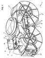
- FIG. 1 an embodiment of a fan housing 1 according to the invention with integrally formed on the outside 4 of the fan housing 1 receiving devices 2 is shown.
- the receiving devices 2 are different pronounced.
- the recording devices are 2 webs, the technical components 3, such as a capacitor 9 or a printed circuit board 11, record positively and non-positively, in part, the receiving devices 2 wells or open housing, the components 3, such as a power connector 10 or control boards 12, 13, positive and non-positive hold.
- the receiving device 2 for the mains connection 10 is designed in the form of a box and has a closure element 6 in the form of a lid, through which the receiving device 2 can be closed.
- the closure element 6 is rotatably or pivotably mounted on fastening devices 5 of the receiving device 2 for the mains connection 10.
- a device for strain relief 8 is arranged in each case.
- both devices for strain relief 8 form an effective device for strain relief 8, for example a cable, which is guided through the opening 7 into the interior of the receiving device 2 for the network connection 10.
- the cable sits in a secure fit and is secured against rotation in the opening 7 of the receiving device 2.
- the receiving device 2 for the control board 12 is formed in the form of a box and has as fastening means 5 grooves and Klips emulate on the side walls of the box, which hold the control board 12 positively and non-positively in the receiving device 2.
- the control board 12 is inserted into the grooves and fastened by Klips emulate.
- the receiving device 2 may have a plurality of grooves, so that a plurality of control boards 12 or control boards 12 with different dimensions can be inserted.
- FIG. 1 a recording device 2 for a capacitor 9 is shown.
- This receiving device 2 consists of several integrally formed on the outer side 4 of the fan housing 1 webs 5.
- the outer side 4 itself also serves as part of the receiving device 2, since the capacitor 9 between a formed in the outside 4 V and two webs 5, in the V-shaped recess protrude, is inserted.
- a circuit board 11 is arranged at the back of the fan housing 1, a circuit board 11 is arranged.
- the printed circuit board 11, which represents a base board, is at the back of the Housing 1, attached.
- a simple wiring of the individual technical components 3 is made possible.
- the circuit board 11 plug contacts for the individual technical components.
- the recording device 2 is provided for the capacitor between the two housing parts for two fans.
- the condenser 9 is held in this worm housing by the outer wall 4 of the housing 1, and the struts 5, which extend into the gusset region.
- the printed circuit board is preferably attached to the back of the screw housing in order to easily realize a connection to the individual technical components.
- the control board is fixed in the illustrated embodiment in a receiving device 2, which is arranged on the side of the fan housing 1.
- a receiving device 2 which is arranged on the side of the fan housing 1.
- the printed circuit board 12 in the receiving device 2 from the rear, d. H. from the side of the rear wall of the fan housing 1 are inserted.
- the receiving device 2 for the mains connection 10 is provided in the illustrated form at the top of the housing 1. In this way, easy access to the mains connection 10 can be ensured even in the assembled state of the fan housing.
- the receiving devices 2 are formed directly on the fan housing.
- FIG. 2 is a perspective view of a section of the fan housing 1 with recording devices 2, shown.
- a circuit board 11 and a capacitor 9 is arranged on the fan housing 1.
- the condenser 9 is arranged between elongate webs 5, and the outside 4 of the fan housing 1.
- the capacitor 9 can be inserted positively into the receiving device.
- the printed circuit board 11 has plugs in the left area, via which the printed circuit board 11 can be connected to the controller, which can be arranged on the circuit board 12.
- the controller which can be arranged on the circuit board 12.
- a connector for the capacitor is provided on the right side of the circuit board. This circuit board is thus a simple wiring of the fan allows.
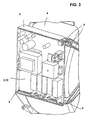
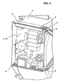
- the Figures 3 and 4 show a perspective view of a section of the fan housing 1 with a receiving devices 2 for a first and another control board 12, 13.
- the receiving device 2 has three side walls and is open to the front.
- On its inner circumferential surface a plurality of parallel grooves 5 are provided, in which the control boards 12, 13 are inserted.
- the control boards 12, 13 held firmly in the grooves.
- the grooves may have different dimensions, so that different sized control boards 12, 13 are inserted into it. In this way, an easy replacement of the control boards 12, 13 take place.
- FIG. 5 shows an enlarged perspective view of a section of the fan housing 1 according to the invention with a receiving devices 2 for a network connection 10.
- the power connector 10 is located in the receiving device 2.
- the receiving device 2 has fastening devices 5 for receiving a closure element 6, in particular a pivotally held lid, and an opening 7 for the passage of a cable.
- the cable is held firmly and non-rotatably in the receiving device 2 by means of the device for strain relief 8 when the closure element 6 closes the receiving device 2.
- the closure element 6 in turn has fastening devices 5, which enable a releasable fastening of the closure element 6 to the receiving device 2.
- the fan housing 1 according to the invention can be made of plastic or metal.
- a plastic housing can be easily and inexpensively manufactured by an injection molding process.
Landscapes
- Engineering & Computer Science (AREA)
- Mechanical Engineering (AREA)
- General Engineering & Computer Science (AREA)
- Chemical & Material Sciences (AREA)
- Combustion & Propulsion (AREA)
- Cooling Or The Like Of Electrical Apparatus (AREA)
- Casings For Electric Apparatus (AREA)
- Structures Of Non-Positive Displacement Pumps (AREA)
- Connector Housings Or Holding Contact Members (AREA)
Claims (10)
- Boîtier de ventilateur (1) pour le montage dans une hotte aspirante, notamment dans une hotte aspirante à capot plat, le boîtier de ventilateur entourant au moins un ventilateur, caractérisé en ce qu'au moins un dispositif de logement de condensateur, au moins un dispositif de logement de platine de commande, au moins un dispositif de logement de connecteur réseau, lequel représente un approfondissement ou un boîtier ouvert, et/ou au moins un dispositif de logement pour une plaquette à circuit imprimé sont réalisés d'une seule pièce avec le boîtier de ventilateur (1).
- Boîtier de ventilateur (1) selon la revendication 1, caractérisé en ce que le boîtier de ventilateur (1) présente au moins un dispositif de logement de platine de commande comprenant des agencements de fixation (5) pour la fixation amovible de composants techniques (3) destinés au fonctionnement du ventilateur, au moins un des agencements de fixation (5) présentant des rainures pour insérer les composants (3) et des éléments à encliqueter pour le maintien des composants (3) dans les rainures.
- Boîtier de ventilateur (1) selon la revendication 2, caractérisé en ce que le dispositif de logement de platine de commande est réalisé d'une seule pièce avec le boîtier de ventilateur (1).
- Boîtier de ventilateur (1) selon les revendications 1 à 3, caractérisé en ce qu'au moins un des dispositifs de logement (2) est disposé sur le côté extérieur (4) du boîtier de ventilateur (1).
- Boîtier de ventilateur (1) selon l'une quelconque des revendications 2 à 4, caractérisé en ce qu'au moins un des composants techniques (3) est logé par adhérence de forme et/ou par adhérence dans au moins un des dispositifs de logements (2).
- Boîtier de ventilateur (1) selon l'une quelconque des revendications 1 à 5, caractérisé en ce qu'au moins un des dispositifs de logement (2) présente un élément de fermeture (6), notamment un couvercle, destiné à fermer le dispositif de logement (2).
- Boîtier de ventilateur (1) selon l'une quelconque des revendications 1 à 6, caractérisé en ce qu'au moins un des dispositifs de logement (2) présente au moins une ouverture (7) pour le passage d'un câble.
- Boîtier de ventilateur (1) selon l'une quelconque des revendications 1 à 7, caractérisé en ce qu'au moins un des dispositifs de logement (2) présente au moins un dispositif de décharge de traction (8) d'un câble.
- Boîtier de ventilateur (1) selon l'une quelconque des revendications 2 à 8, caractérisé en ce que le boîtier de ventilateur (1) présente des canaux, des dispositifs de guidage et/ou des supports pour la fixation ou le passage de lignes électriques pour la connexion des composants techniques (3) entre eux.
- Boîtier de ventilateur (1) selon l'une quelconque des revendications 1 à 9, caractérisé en ce que le boîtier de ventilateur (1) est ménagé pour le montage dans le canal d'évacuation resp. le conduit d'évacuation de la hotte aspirante.
Applications Claiming Priority (3)
| Application Number | Priority Date | Filing Date | Title |
|---|---|---|---|
| DE10259761A DE10259761A1 (de) | 2002-12-19 | 2002-12-19 | Lüftergehäuse |
| DE10259761 | 2002-12-19 | ||
| PCT/EP2003/013782 WO2004057239A1 (fr) | 2002-12-19 | 2003-12-05 | Boitier pour ventilateur aspirant |
Publications (2)
| Publication Number | Publication Date |
|---|---|
| EP1579153A1 EP1579153A1 (fr) | 2005-09-28 |
| EP1579153B1 true EP1579153B1 (fr) | 2013-03-06 |
Family
ID=32477838
Family Applications (1)
| Application Number | Title | Priority Date | Filing Date |
|---|---|---|---|
| EP03782315A Expired - Lifetime EP1579153B1 (fr) | 2002-12-19 | 2003-12-05 | Boitier pour ventilateur aspirant |
Country Status (8)
| Country | Link |
|---|---|
| US (1) | US20070010187A1 (fr) |
| EP (1) | EP1579153B1 (fr) |
| CN (1) | CN100338398C (fr) |
| AU (1) | AU2003289967A1 (fr) |
| DE (1) | DE10259761A1 (fr) |
| ES (1) | ES2401791T3 (fr) |
| PL (1) | PL215616B1 (fr) |
| WO (1) | WO2004057239A1 (fr) |
Cited By (2)
| Publication number | Priority date | Publication date | Assignee | Title |
|---|---|---|---|---|
| DE102013210764A1 (de) * | 2013-06-10 | 2014-12-11 | BSH Bosch und Siemens Hausgeräte GmbH | Lüftervorrichtung für eine Dunstabzugshaube und Dunstabzugshaube |
| DE102021204153A1 (de) | 2021-04-27 | 2022-10-27 | BSH Hausgeräte GmbH | Gebläsegehäuse für ein Gebläse einer Dunstabzugsvorrichtung und Gebläse für Dunstabzugsvorrichtung |
Families Citing this family (6)
| Publication number | Priority date | Publication date | Assignee | Title |
|---|---|---|---|---|
| DE102007021318A1 (de) | 2007-05-07 | 2008-11-13 | BSH Bosch und Siemens Hausgeräte GmbH | Dunstabzugsgehäuse und Dunstabzugshaube |
| EP2098287A1 (fr) | 2008-03-03 | 2009-09-09 | ExxonMobil Chemical Patents Inc. | Procédé de formulation de composition de catalyseur de tamis moléculaire en contrôlant un ajout de composant |
| DE102009055075A1 (de) * | 2009-12-21 | 2011-06-22 | BSH Bosch und Siemens Hausgeräte GmbH, 81739 | Lüfterkasten für Dunstabzugshaube |
| EP2397699A1 (fr) * | 2010-06-16 | 2011-12-21 | Behr France Rouffach SAS | Ventilateur pour une climatisation de véhicule automobile |
| DE102015202841A1 (de) * | 2015-02-17 | 2016-08-18 | BSH Hausgeräte GmbH | Lüfterkasten für Dunstabzugshaube und Dunstabzugshaube |
| BE1031888B1 (de) * | 2023-08-09 | 2025-03-10 | Miele & Cie | Elektronikmodul für ein Haushaltsgerät und Verfahren zur Herstellung eines Elektronikmoduls für ein Haushaltsgerät |
Family Cites Families (21)
| Publication number | Priority date | Publication date | Assignee | Title |
|---|---|---|---|---|
| US3354454A (en) * | 1966-11-04 | 1967-11-21 | Amp Inc | One-piece signal housing |
| SE385092B (sv) * | 1975-11-05 | 1976-06-08 | Futurumverken Ab | Koksventilator |
| DE2718889A1 (de) * | 1976-10-06 | 1978-04-13 | Giampieretti & Crescentini Fab | Raumluftreinigungsvorrichtung |
| US4089328A (en) * | 1976-11-02 | 1978-05-16 | Futurumverken Ab | Kitchen ventilator |
| DE3514712A1 (de) * | 1985-04-24 | 1986-10-30 | Buderus Ag, 6330 Wetzlar | Dunstabzugshaube |
| DE3545680C2 (de) * | 1985-12-21 | 1995-11-23 | Mulfingen Elektrobau Ebm | Ventilatorgehäuse mit Schutzgitter |
| US4818822A (en) * | 1987-11-04 | 1989-04-04 | Yahraus Norman J | Junction box |
| US4842227A (en) * | 1988-04-11 | 1989-06-27 | Thermo King Corporation | Strain relief clamp |
| DE9016767U1 (de) * | 1990-12-12 | 1991-02-28 | Ebm Elektrobau Mulfingen Gmbh & Co, 7119 Mulfingen | Dunstabzugshaube |
| DE4106130A1 (de) * | 1991-02-27 | 1992-09-03 | Licentia Gmbh | Durch einen buerstenlosen gleichstrommotor angetriebenes geblaese mit einem spiralfoermigen gehaeuse |
| IT1278953B1 (it) * | 1995-01-12 | 1997-12-02 | Turboair Spa | Cappa da cucina comprendente un gruppo di aspirazione e/o filtrazione |
| AT912U1 (de) * | 1995-07-27 | 1996-07-25 | Balzer Luefter Gmbh | Lüfter mit austauschbarem funktionsbaustein, insbesonders elektrischem steuerbaustein |
| CN2310257Y (zh) * | 1996-07-31 | 1999-03-10 | 王习之 | 一种抽油烟机顶壳 |
| US5883784A (en) * | 1997-04-04 | 1999-03-16 | Northern Telecom Limited | Mounting structure for heat conductively supporting a planar electric device |
| DE19841762C2 (de) * | 1998-09-11 | 2002-07-18 | Ebm Werke Gmbh & Co Kg | Gebläsegehäuse und Radialgebläse |
| US6144556A (en) * | 1999-03-30 | 2000-11-07 | Lanclos; Kenneth W. | Heat dissipating housing for electronic components |
| US6354287B1 (en) * | 1999-10-01 | 2002-03-12 | Fuji Industrial Co., Ltd. | Blower unit for range hood and temporary fixing structure for blower unit |
| DE19950245C1 (de) * | 1999-10-19 | 2001-05-10 | Ebm Werke Gmbh & Co Kg | Radialgebläse |
| DE20015726U1 (de) * | 2000-09-12 | 2002-01-31 | ebm Werke GmbH & Co. KG, 74673 Mulfingen | Elektrische Anschlußanordnung für eine Dunstabzugshaube |
| EP1464106A1 (fr) * | 2002-01-11 | 2004-10-06 | ebm-papst St. Georgen GmbH & Co. KG | Ventilateur miniature ou micro-ventilateur |
| US6827560B2 (en) * | 2002-04-04 | 2004-12-07 | Jakel Incorporated | Two-piece motor cooling and exhaust diluting blower housing |
-
2002
- 2002-12-19 DE DE10259761A patent/DE10259761A1/de not_active Withdrawn
-
2003
- 2003-12-05 WO PCT/EP2003/013782 patent/WO2004057239A1/fr not_active Ceased
- 2003-12-05 AU AU2003289967A patent/AU2003289967A1/en not_active Abandoned
- 2003-12-05 EP EP03782315A patent/EP1579153B1/fr not_active Expired - Lifetime
- 2003-12-05 CN CNB2003801070603A patent/CN100338398C/zh not_active Expired - Fee Related
- 2003-12-05 PL PL375870A patent/PL215616B1/pl unknown
- 2003-12-05 ES ES03782315T patent/ES2401791T3/es not_active Expired - Lifetime
- 2003-12-05 US US10/539,702 patent/US20070010187A1/en not_active Abandoned
Cited By (3)
| Publication number | Priority date | Publication date | Assignee | Title |
|---|---|---|---|---|
| DE102013210764A1 (de) * | 2013-06-10 | 2014-12-11 | BSH Bosch und Siemens Hausgeräte GmbH | Lüftervorrichtung für eine Dunstabzugshaube und Dunstabzugshaube |
| DE102021204153A1 (de) | 2021-04-27 | 2022-10-27 | BSH Hausgeräte GmbH | Gebläsegehäuse für ein Gebläse einer Dunstabzugsvorrichtung und Gebläse für Dunstabzugsvorrichtung |
| WO2022228910A1 (fr) | 2021-04-27 | 2022-11-03 | BSH Hausgeräte GmbH | Enveloppe de ventilateur pour ventilateur de dispositif d'extraction, et ventilateur pour dispositif d'extraction |
Also Published As
| Publication number | Publication date |
|---|---|
| AU2003289967A1 (en) | 2004-07-14 |
| ES2401791T3 (es) | 2013-04-24 |
| CN1729372A (zh) | 2006-02-01 |
| WO2004057239A1 (fr) | 2004-07-08 |
| PL375870A1 (en) | 2005-12-12 |
| EP1579153A1 (fr) | 2005-09-28 |
| DE10259761A1 (de) | 2004-07-08 |
| CN100338398C (zh) | 2007-09-19 |
| US20070010187A1 (en) | 2007-01-11 |
| PL215616B1 (pl) | 2014-01-31 |
Similar Documents
| Publication | Publication Date | Title |
|---|---|---|
| EP2156100B1 (fr) | Logement pour hotte aspirante et hotte aspirante | |
| DE19925439B4 (de) | Lüfter | |
| DE10051643B4 (de) | Haube für einen Lüfterfilter | |
| DE10318062A1 (de) | Getriebe-Antriebseinheit mit Elektronik-Schnittstelle | |
| EP1579153B1 (fr) | Boitier pour ventilateur aspirant | |
| DE102008050376B4 (de) | Wärmetauscher für ein Klimatisierungsgerät und Klimatisierungsgerät | |
| EP3101350B1 (fr) | Unite de ventilateur pour hotte aspirante et hotte aspirante | |
| EP0847889B1 (fr) | Unité d'affichage | |
| EP3059505B1 (fr) | Caisson de ventilateur pour hotte aspirante et hotte aspirante | |
| EP1000783A1 (fr) | Ventilateur radial avec raccord de connexion | |
| DE4008272C1 (en) | Switch cabinet with through-ways for ventilation - consisting of regular openings in wall closable by descending short wall | |
| DE102005015318B4 (de) | Gehäuseeinheit mit Öffnungs- und Schließvorrichtung und elektrisches Gerät | |
| DE102015212283B4 (de) | Lüftergehäuse für eine Dunstabzugshaube | |
| DE10330315B4 (de) | Filterlüfter | |
| DE102004045488B4 (de) | Kühlsystem | |
| DE4420983A1 (de) | Gehäuse für elektronische Steckbaugruppen | |
| DE102023110948B4 (de) | Vorrichtung zur verankerung eines installationskastens, installationskasten und verfahren zur verankerung eines installationskastens in einer hohlwand | |
| DE202019002833U1 (de) | Kabeldurchführung für einen Steuerungsschrank | |
| DE102020206865B4 (de) | Kochfeld, Anordnung eines Kochfelds in einer Arbeitsplatte und Verfahren zum Anordnen eines Kochfelds in einer Arbeitsplatte | |
| DE10142497B9 (de) | Gerätegehäuse eines elektronischen Gerätes zum stationären Einsatz | |
| DE202023106876U1 (de) | Gehäuseelement für ein Kochgerät | |
| DE29620388U1 (de) | Abgeschirmtes Gehäuse für ein Verteilerfeld | |
| DE3613035C2 (fr) | ||
| EP3196556A1 (fr) | Hotte aspirante | |
| EP0837540A1 (fr) | Moteur électrique d'un ventilateur à boítier reconfigurable |
Legal Events
| Date | Code | Title | Description |
|---|---|---|---|
| PUAI | Public reference made under article 153(3) epc to a published international application that has entered the european phase |
Free format text: ORIGINAL CODE: 0009012 |
|
| 17P | Request for examination filed |
Effective date: 20050719 |
|
| AK | Designated contracting states |
Kind code of ref document: A1 Designated state(s): AT BE BG CH CY CZ DE DK EE ES FI FR GB GR HU IE IT LI LU MC NL PT RO SE SI SK TR |
|
| AX | Request for extension of the european patent |
Extension state: AL LT LV MK |
|
| DAX | Request for extension of the european patent (deleted) | ||
| RIN1 | Information on inventor provided before grant (corrected) |
Inventor name: KRAUTER, JOCHEN Inventor name: HONDMANN, FRANK Inventor name: NEUSCHL, HELMUT |
|
| 17Q | First examination report despatched |
Effective date: 20091118 |
|
| GRAP | Despatch of communication of intention to grant a patent |
Free format text: ORIGINAL CODE: EPIDOSNIGR1 |
|
| GRAS | Grant fee paid |
Free format text: ORIGINAL CODE: EPIDOSNIGR3 |
|
| GRAA | (expected) grant |
Free format text: ORIGINAL CODE: 0009210 |
|
| AK | Designated contracting states |
Kind code of ref document: B1 Designated state(s): AT BE BG CH CY CZ DE DK EE ES FI FR GB GR HU IE IT LI LU MC NL PT RO SE SI SK TR |
|
| REG | Reference to a national code |
Ref country code: GB Ref legal event code: FG4D Free format text: NOT ENGLISH |
|
| REG | Reference to a national code |
Ref country code: CH Ref legal event code: EP Ref country code: AT Ref legal event code: REF Ref document number: 599859 Country of ref document: AT Kind code of ref document: T Effective date: 20130315 |
|
| REG | Reference to a national code |
Ref country code: IE Ref legal event code: FG4D Free format text: LANGUAGE OF EP DOCUMENT: GERMAN |
|
| REG | Reference to a national code |
Ref country code: ES Ref legal event code: FG2A Ref document number: 2401791 Country of ref document: ES Kind code of ref document: T3 Effective date: 20130424 |
|
| REG | Reference to a national code |
Ref country code: DE Ref legal event code: R096 Ref document number: 50314716 Country of ref document: DE Effective date: 20130502 |
|
| PG25 | Lapsed in a contracting state [announced via postgrant information from national office to epo] |
Ref country code: BG Free format text: LAPSE BECAUSE OF FAILURE TO SUBMIT A TRANSLATION OF THE DESCRIPTION OR TO PAY THE FEE WITHIN THE PRESCRIBED TIME-LIMIT Effective date: 20130606 Ref country code: SE Free format text: LAPSE BECAUSE OF FAILURE TO SUBMIT A TRANSLATION OF THE DESCRIPTION OR TO PAY THE FEE WITHIN THE PRESCRIBED TIME-LIMIT Effective date: 20130306 |
|
| REG | Reference to a national code |
Ref country code: NL Ref legal event code: VDEP Effective date: 20130306 |
|
| PG25 | Lapsed in a contracting state [announced via postgrant information from national office to epo] |
Ref country code: FI Free format text: LAPSE BECAUSE OF FAILURE TO SUBMIT A TRANSLATION OF THE DESCRIPTION OR TO PAY THE FEE WITHIN THE PRESCRIBED TIME-LIMIT Effective date: 20130306 Ref country code: GR Free format text: LAPSE BECAUSE OF FAILURE TO SUBMIT A TRANSLATION OF THE DESCRIPTION OR TO PAY THE FEE WITHIN THE PRESCRIBED TIME-LIMIT Effective date: 20130607 Ref country code: SI Free format text: LAPSE BECAUSE OF FAILURE TO SUBMIT A TRANSLATION OF THE DESCRIPTION OR TO PAY THE FEE WITHIN THE PRESCRIBED TIME-LIMIT Effective date: 20130306 |
|
| PG25 | Lapsed in a contracting state [announced via postgrant information from national office to epo] |
Ref country code: CZ Free format text: LAPSE BECAUSE OF FAILURE TO SUBMIT A TRANSLATION OF THE DESCRIPTION OR TO PAY THE FEE WITHIN THE PRESCRIBED TIME-LIMIT Effective date: 20130306 Ref country code: SK Free format text: LAPSE BECAUSE OF FAILURE TO SUBMIT A TRANSLATION OF THE DESCRIPTION OR TO PAY THE FEE WITHIN THE PRESCRIBED TIME-LIMIT Effective date: 20130306 Ref country code: EE Free format text: LAPSE BECAUSE OF FAILURE TO SUBMIT A TRANSLATION OF THE DESCRIPTION OR TO PAY THE FEE WITHIN THE PRESCRIBED TIME-LIMIT Effective date: 20130306 Ref country code: RO Free format text: LAPSE BECAUSE OF FAILURE TO SUBMIT A TRANSLATION OF THE DESCRIPTION OR TO PAY THE FEE WITHIN THE PRESCRIBED TIME-LIMIT Effective date: 20130306 Ref country code: NL Free format text: LAPSE BECAUSE OF FAILURE TO SUBMIT A TRANSLATION OF THE DESCRIPTION OR TO PAY THE FEE WITHIN THE PRESCRIBED TIME-LIMIT Effective date: 20130306 Ref country code: PT Free format text: LAPSE BECAUSE OF FAILURE TO SUBMIT A TRANSLATION OF THE DESCRIPTION OR TO PAY THE FEE WITHIN THE PRESCRIBED TIME-LIMIT Effective date: 20130708 |
|
| PG25 | Lapsed in a contracting state [announced via postgrant information from national office to epo] |
Ref country code: CY Free format text: LAPSE BECAUSE OF FAILURE TO SUBMIT A TRANSLATION OF THE DESCRIPTION OR TO PAY THE FEE WITHIN THE PRESCRIBED TIME-LIMIT Effective date: 20130306 |
|
| PLBE | No opposition filed within time limit |
Free format text: ORIGINAL CODE: 0009261 |
|
| STAA | Information on the status of an ep patent application or granted ep patent |
Free format text: STATUS: NO OPPOSITION FILED WITHIN TIME LIMIT |
|
| PG25 | Lapsed in a contracting state [announced via postgrant information from national office to epo] |
Ref country code: DK Free format text: LAPSE BECAUSE OF FAILURE TO SUBMIT A TRANSLATION OF THE DESCRIPTION OR TO PAY THE FEE WITHIN THE PRESCRIBED TIME-LIMIT Effective date: 20130306 |
|
| 26N | No opposition filed |
Effective date: 20131209 |
|
| REG | Reference to a national code |
Ref country code: DE Ref legal event code: R097 Ref document number: 50314716 Country of ref document: DE Effective date: 20131209 |
|
| BERE | Be: lapsed |
Owner name: BSH BOSCH UND SIEMENS HAUSGERATE G.M.B.H. Effective date: 20131231 |
|
| REG | Reference to a national code |
Ref country code: CH Ref legal event code: PL |
|
| PG25 | Lapsed in a contracting state [announced via postgrant information from national office to epo] |
Ref country code: MC Free format text: LAPSE BECAUSE OF FAILURE TO SUBMIT A TRANSLATION OF THE DESCRIPTION OR TO PAY THE FEE WITHIN THE PRESCRIBED TIME-LIMIT Effective date: 20130306 Ref country code: LU Free format text: LAPSE BECAUSE OF FAILURE TO SUBMIT A TRANSLATION OF THE DESCRIPTION OR TO PAY THE FEE WITHIN THE PRESCRIBED TIME-LIMIT Effective date: 20131205 |
|
| REG | Reference to a national code |
Ref country code: IE Ref legal event code: MM4A |
|
| PG25 | Lapsed in a contracting state [announced via postgrant information from national office to epo] |
Ref country code: IE Free format text: LAPSE BECAUSE OF NON-PAYMENT OF DUE FEES Effective date: 20131205 Ref country code: BE Free format text: LAPSE BECAUSE OF NON-PAYMENT OF DUE FEES Effective date: 20131231 Ref country code: CH Free format text: LAPSE BECAUSE OF NON-PAYMENT OF DUE FEES Effective date: 20131231 Ref country code: LI Free format text: LAPSE BECAUSE OF NON-PAYMENT OF DUE FEES Effective date: 20131231 |
|
| REG | Reference to a national code |
Ref country code: AT Ref legal event code: MM01 Ref document number: 599859 Country of ref document: AT Kind code of ref document: T Effective date: 20131205 |
|
| REG | Reference to a national code |
Ref country code: DE Ref legal event code: R081 Ref document number: 50314716 Country of ref document: DE Owner name: BSH HAUSGERAETE GMBH, DE Free format text: FORMER OWNER: BSH BOSCH UND SIEMENS HAUSGERAETE GMBH, 81739 MUENCHEN, DE Effective date: 20130306 Ref country code: DE Ref legal event code: R081 Ref document number: 50314716 Country of ref document: DE Owner name: BSH HAUSGERAETE GMBH, DE Free format text: FORMER OWNER: BSH BOSCH UND SIEMENS HAUSGERAETE GMBH, 81739 MUENCHEN, DE Effective date: 20150407 |
|
| PG25 | Lapsed in a contracting state [announced via postgrant information from national office to epo] |
Ref country code: AT Free format text: LAPSE BECAUSE OF NON-PAYMENT OF DUE FEES Effective date: 20131205 |
|
| REG | Reference to a national code |
Ref country code: ES Ref legal event code: PC2A Owner name: BSH HAUSGERATE GMBH Effective date: 20150527 |
|
| PG25 | Lapsed in a contracting state [announced via postgrant information from national office to epo] |
Ref country code: TR Free format text: LAPSE BECAUSE OF FAILURE TO SUBMIT A TRANSLATION OF THE DESCRIPTION OR TO PAY THE FEE WITHIN THE PRESCRIBED TIME-LIMIT Effective date: 20130306 |
|
| PG25 | Lapsed in a contracting state [announced via postgrant information from national office to epo] |
Ref country code: HU Free format text: LAPSE BECAUSE OF FAILURE TO SUBMIT A TRANSLATION OF THE DESCRIPTION OR TO PAY THE FEE WITHIN THE PRESCRIBED TIME-LIMIT; INVALID AB INITIO Effective date: 20031205 |
|
| REG | Reference to a national code |
Ref country code: FR Ref legal event code: CD Owner name: BSH HAUSGERATE GMBH Effective date: 20151022 |
|
| REG | Reference to a national code |
Ref country code: FR Ref legal event code: PLFP Year of fee payment: 13 |
|
| REG | Reference to a national code |
Ref country code: FR Ref legal event code: PLFP Year of fee payment: 14 |
|
| PGFP | Annual fee paid to national office [announced via postgrant information from national office to epo] |
Ref country code: GB Payment date: 20161222 Year of fee payment: 14 |
|
| PGFP | Annual fee paid to national office [announced via postgrant information from national office to epo] |
Ref country code: IT Payment date: 20161220 Year of fee payment: 14 Ref country code: FR Payment date: 20161221 Year of fee payment: 14 Ref country code: ES Payment date: 20161221 Year of fee payment: 14 |
|
| PGFP | Annual fee paid to national office [announced via postgrant information from national office to epo] |
Ref country code: DE Payment date: 20161231 Year of fee payment: 14 |
|
| REG | Reference to a national code |
Ref country code: DE Ref legal event code: R119 Ref document number: 50314716 Country of ref document: DE |
|
| GBPC | Gb: european patent ceased through non-payment of renewal fee |
Effective date: 20171205 |
|
| REG | Reference to a national code |
Ref country code: FR Ref legal event code: ST Effective date: 20180831 |
|
| PG25 | Lapsed in a contracting state [announced via postgrant information from national office to epo] |
Ref country code: FR Free format text: LAPSE BECAUSE OF NON-PAYMENT OF DUE FEES Effective date: 20180102 Ref country code: IT Free format text: LAPSE BECAUSE OF NON-PAYMENT OF DUE FEES Effective date: 20171205 Ref country code: DE Free format text: LAPSE BECAUSE OF NON-PAYMENT OF DUE FEES Effective date: 20180703 |
|
| PG25 | Lapsed in a contracting state [announced via postgrant information from national office to epo] |
Ref country code: GB Free format text: LAPSE BECAUSE OF NON-PAYMENT OF DUE FEES Effective date: 20171205 |
|
| REG | Reference to a national code |
Ref country code: ES Ref legal event code: FD2A Effective date: 20190702 |
|
| PG25 | Lapsed in a contracting state [announced via postgrant information from national office to epo] |
Ref country code: ES Free format text: LAPSE BECAUSE OF NON-PAYMENT OF DUE FEES Effective date: 20171206 |