EP1579199B1 - Vorrichtung zum nachweis der korrosion - Google Patents
Vorrichtung zum nachweis der korrosion Download PDFInfo
- Publication number
- EP1579199B1 EP1579199B1 EP03796165A EP03796165A EP1579199B1 EP 1579199 B1 EP1579199 B1 EP 1579199B1 EP 03796165 A EP03796165 A EP 03796165A EP 03796165 A EP03796165 A EP 03796165A EP 1579199 B1 EP1579199 B1 EP 1579199B1
- Authority
- EP
- European Patent Office
- Prior art keywords
- pellet
- medium
- corrosion
- refractive index
- chamber
- Prior art date
- Legal status (The legal status is an assumption and is not a legal conclusion. Google has not performed a legal analysis and makes no representation as to the accuracy of the status listed.)
- Expired - Lifetime
Links
- 230000007797 corrosion Effects 0.000 title claims description 34
- 238000005260 corrosion Methods 0.000 title claims description 34
- 239000013307 optical fiber Substances 0.000 claims abstract description 27
- 239000012530 fluid Substances 0.000 claims abstract description 12
- 238000005259 measurement Methods 0.000 claims abstract description 12
- 239000000463 material Substances 0.000 claims description 6
- 230000005540 biological transmission Effects 0.000 claims description 4
- 239000004020 conductor Substances 0.000 claims description 3
- 239000008188 pellet Substances 0.000 abstract description 42
- 239000000126 substance Substances 0.000 abstract 2
- 239000003518 caustics Substances 0.000 abstract 1
- 239000002775 capsule Substances 0.000 description 10
- 239000000835 fiber Substances 0.000 description 10
- 238000001514 detection method Methods 0.000 description 5
- 239000002184 metal Substances 0.000 description 3
- 238000012544 monitoring process Methods 0.000 description 3
- 235000010603 pastilles Nutrition 0.000 description 3
- 239000011148 porous material Substances 0.000 description 3
- 238000013461 design Methods 0.000 description 2
- 230000000694 effects Effects 0.000 description 2
- 230000003287 optical effect Effects 0.000 description 2
- 238000012360 testing method Methods 0.000 description 2
- 238000002604 ultrasonography Methods 0.000 description 2
- 240000008042 Zea mays Species 0.000 description 1
- 238000004891 communication Methods 0.000 description 1
- 238000000151 deposition Methods 0.000 description 1
- 229930195733 hydrocarbon Natural products 0.000 description 1
- 150000002430 hydrocarbons Chemical class 0.000 description 1
- 238000009434 installation Methods 0.000 description 1
- 239000007788 liquid Substances 0.000 description 1
- 239000012528 membrane Substances 0.000 description 1
- 230000035515 penetration Effects 0.000 description 1
- 230000035699 permeability Effects 0.000 description 1
- 238000012545 processing Methods 0.000 description 1
- 239000011347 resin Substances 0.000 description 1
- 229920005989 resin Polymers 0.000 description 1
Images


Classifications
-
- G—PHYSICS
- G01—MEASURING; TESTING
- G01N—INVESTIGATING OR ANALYSING MATERIALS BY DETERMINING THEIR CHEMICAL OR PHYSICAL PROPERTIES
- G01N21/00—Investigating or analysing materials by the use of optical means, i.e. using sub-millimetre waves, infrared, visible or ultraviolet light
- G01N21/17—Systems in which incident light is modified in accordance with the properties of the material investigated
- G01N21/41—Refractivity; Phase-affecting properties, e.g. optical path length
- G01N21/43—Refractivity; Phase-affecting properties, e.g. optical path length by measuring critical angle
-
- G—PHYSICS
- G01—MEASURING; TESTING
- G01N—INVESTIGATING OR ANALYSING MATERIALS BY DETERMINING THEIR CHEMICAL OR PHYSICAL PROPERTIES
- G01N21/00—Investigating or analysing materials by the use of optical means, i.e. using sub-millimetre waves, infrared, visible or ultraviolet light
- G01N21/17—Systems in which incident light is modified in accordance with the properties of the material investigated
- G01N21/41—Refractivity; Phase-affecting properties, e.g. optical path length
- G01N21/43—Refractivity; Phase-affecting properties, e.g. optical path length by measuring critical angle
- G01N21/431—Dip refractometers, e.g. using optical fibres
-
- G—PHYSICS
- G01—MEASURING; TESTING
- G01N—INVESTIGATING OR ANALYSING MATERIALS BY DETERMINING THEIR CHEMICAL OR PHYSICAL PROPERTIES
- G01N17/00—Investigating resistance of materials to the weather, to corrosion, or to light
- G01N17/04—Corrosion probes
-
- G—PHYSICS
- G01—MEASURING; TESTING
- G01N—INVESTIGATING OR ANALYSING MATERIALS BY DETERMINING THEIR CHEMICAL OR PHYSICAL PROPERTIES
- G01N21/00—Investigating or analysing materials by the use of optical means, i.e. using sub-millimetre waves, infrared, visible or ultraviolet light
- G01N21/17—Systems in which incident light is modified in accordance with the properties of the material investigated
- G01N21/41—Refractivity; Phase-affecting properties, e.g. optical path length
Definitions
- the present invention relates to a corrosion detection device in which the measurement of a refractive index is used to obtain and transmit a signal representative of a state of corrosion.
- This invention can be advantageously applied to detect the corrosion of an effluent transport line, for example hydrocarbons.
- an optical fiber is used.
- the present invention has the advantages of simplicity, accuracy and easy adaptability to different implementations of devices subject to corrosion conditions.
- the present invention relates to a device for detecting corrosion induced by a medium, comprising: a chamber closed by a pellet made of a material such that the pellet becomes permeable to the medium once corroded by this medium, and measurement means of the refractive index of the fluid present in the chamber.
- the measuring means may comprise a light source and a photo detector.
- the means for measuring the refractive index may comprise at least one portion of optical fiber.
- One end of the optical fiber may be close to the pellet.
- the room may contain air.
- the pellet may be bonded to a pressure-resistant medium of the corrosive medium.
- the support can be permeable in the middle.
- the device may comprise means for balancing the pressure on either side of the pellet.
- the means for measuring the refractive index may be included in the chamber.
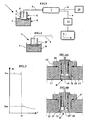
- the figure 1 shows a sensor 1 placed in a corrosive liquid 2.
- the sensor 1 is constituted by a housing 3 closed by a pellet 4 which separates the internal volume 5 of the housing from the external environment, that is to say the corrosive medium.
- An optical fiber 6 is inserted into the housing 3 in such a way that the end of the fiber is positioned near the chip 4.
- the optical fiber 6 is connected to a coupler 7 consisting of two optical fibers 8 and 9 respectively connected to a light source 10 and to a photo detector 11.
- the light source 10 for example a laser diode, emits a light beam transmitted by the fibers 8 and 6 to the middle now in the internal space of the housing 3.
- the medium A reflects the light beam, according to its own reflection characteristic.
- the reflected ray is transmitted via the optical fiber 6 to the coupler 7, which guides the spoke light reflected towards the optical fiber 9 connected to a photodiode, for example a photodiode, adapted to measure the intensity of the ray reflected by the medium A now inside the cell.
- the intensity of the reflected ray remains constant.
- the state of conservation of the pellet is thus detected, and it is deduced that there is no effect of corrosion on the pellet.
- the choice of the material of the pellet and its thickness will depend on the desired alarm level under given corrosion service conditions.
- the material of the pellet is the same as that of the structure subjected to corrosion.
- the thickness of the pellet is preferably chosen less than the thickness determined during the design of the equipment to take account of the corrosion of the structure.
- the figure 2 shows a schematic partial view which illustrates the operating principle of the sensor.
- the pellet 4 was corroded by medium B, which allowed a certain amount of medium B to pass through the pellet to reach the internal space of the cell.
- this amount of medium B ' is sufficient, the intensity of the reflected ray changes significantly insofar as the refractive indices of the media A and B (or B') are different.
- the intensity measurement variation of the reflected ray is therefore indicative of a degree of corrosion, corresponding to the thickness of the pellet 4.
- the figure 3 shows a recording of the signal received by the photodiode Ir as a function of time t.
- the measure IrA gives the level of intensity of the radius incident resulting from the medium A in contact with the end of the optical fiber.
- the pellet 4 was perforated under the effect of corrosion by medium B. In the present test, it is a 5M H 2 SO 4 solution and the metal pellet used has a thickness of 50 microns.
- the photodiode measures the intensity IrB of the reflected ray, intensity significantly lower than that of IrA.
- FIGS. 4A and 4B schematically illustrate principles of different sensor variants according to the invention, adapted to be used for installations in which the corrosive fluid is under pressure.
- the Figure 4A illustrates the principle of a sensor attached to the wall 12 of an envelope containing a corrosive medium B and under pressure.
- the sensor is fixed by a flange 13 on a bore 14 in the wall.
- a pellet 15 of metal sensitive to corrosion is deposited on a support 16 having a permeability to the medium B such that, as soon as the pellet 15 reaches a certain level of corrosion (pitting, porosity, ...), the medium B penetrates up to at the end of the optical fiber 17.
- the support 16 may be a sintered metal, a perforated disk, or the like.
- the functions of this support are to support the pellet in contact with a fluid under pressure, while allowing the medium B to penetrate to the end of the optical fiber 17 following the perforation by corrosion of the pellet 15.
- seals prevent external leakage as soon as the pellet is corroded.
- the Figure 4B schematically illustrates the principle of a pellet 19, thin therefore not very resistant to pressure, but adequate for the determination of a level of corrosion.
- the mounting of the sensor may be identical to that of the realization of the Figure 4A . But here, the chamber 20 in which is the end of the optical fiber 21 is put at the same pressure as that prevailing in the medium B.
- the chamber 20 is filled with a fluid A ', compressibility close to that of the medium B, and pressurized by a pressure transmission device comprising a conduit 22 for taking the pressure in the medium B, pressurizing means 23 (for example a piston, a membrane) of the fluid A ' .
- a pressure transmission device comprising a conduit 22 for taking the pressure in the medium B, pressurizing means 23 (for example a piston, a membrane) of the fluid A ' .
- the pressure is identical on both sides of the pellet, which allows a small thickness.
- the medium B enters the chamber 20 where the fluid A 'is to mix and vary the refractive index.
- the figure 5 illustrates the principle of a variant of the sensor according to the invention.
- the device 30 is fixed on the wall 31 of a structure in contact with the medium corrosive fluids B.
- a pellet 32 closes the end of the body 33 of the sensor.
- a support 34 made of a porous and permeable material, holds the pellet 32 under the pressure forces of the medium B.
- the body of the sensor contains a "capsule" 35 for detecting the variation of the refractive index.
- the schematic representation of the capsule 35 is identical to the representation shown in FIG. Figure 6A , described later.
- This capsule comprises means for transmitting the measurement: by electrical conductor, optical fiber, waves (radio, ultrasound, electromagnetic, ...) as shown schematically by reference 36.
- the sensor may, in a variant, be completely free hardware communication link. It will be simple to multiply the number of sensors placed on a structure to carry out a corrosion management of this structure, for example by using pellets of different thickness at specific locations, or arranging them on the same site to make a local "monitoring" of the corrosion.
- the Figure 6A illustrates a capsule principle 35, in which an optical fiber 37 is held close to the base 38 of the capsule by a resin thickness 39.
- a light source for example a diode
- the base 38 of the capsule is in contact with, or in the vicinity of, the porous material 34 ( figure 5 ), or equivalent, so that the fluid of the medium B which passes through both the corroded pellet 32 and the porous material 34 varies the refractive index at the end of the fiber 37. This variation is measured by the detector 41 (for example a photodiode).
- the capsule also comprises the electronic means (not shown) for managing and processing the information in order to transmit it to the user, for example by waves as illustrated in FIG. figure 5 .
- the Figure 6B shows the use of a diopter 42 consisting of a medium A 'and the medium B' having penetrated into the porous material 34.
- a sensor 43 measures a characteristic of the reflected light beam 44, resulting from an incident ray 45 issuing from a light source 46.
- electronic means internal to the capsule manage and transmit the variation information of the refractive index of the medium B 'to the user.
- the Figure 6C the principle illustrated by the Figures 1, 2, 4A and 4B , in which the sensor contains the end of an optical fiber 50 which is extended by another length of fiber 52, for example connected by a connector 51.
- a measuring capsule 53 contains the source 54 and the measuring means 55 of the variation of the refractive index at the end of the fiber 50.
- FIGS. 7 and 8 illustrate a corrosion detection device in which the advantageous possibility of separating the "corrosion” function from the "corrosion measurement” function is used, which allows different embodiments of the present invention.
- the figure 8 illustrates a corrosion detection device 30 consisting of two parts referenced 60 and 61.
- the portion 60 is fixed on the wall 31 of the structure, and essentially comprises the corrosion pellet 32, the pellet support, or the like, 34, and an optical fiber portion 62 mounted to be able to detect a fluid introduced through the chip and to be connected to an optical link by connection means 63a.
- This part 60 therefore comprises only passive elements.
- Part 61 is the measurement and detection element as such, which comprises connection means 63b cooperating with the connection means 63a of the fixed part 60. As described above, this part comprises the source bright and the sensor measuring the index of refraction. The information is sent to the user by means referenced 36, or by any other equivalent means.
- This embodiment has the following advantages: - easy change of the active part (measurement, transmission); - use of a single measuring device that is connected, as needed, to each of the fixed points of corrosion control.
- the figure 8 is another application of the design principle illustrated by the figure 7 .
- the same fixed part 60 installed on a wall 31 of structure, at the place where a corrosion monitoring must be made.
- another wall 64 does not allow direct access to the part 60 and the connection means 63a to carry out the measurement.
- An optical fiber 65 connected to the internal optical fiber 62, passes through the second wall 64 to be connected to connection means 63c accessible on the second wall 64.
- the optical extension fiber 65 may be continuous with the internal fiber 62, or cooperate with the means 63a by connecting means 63b. To carry out the measurements of control of the state of corrosion of the structure, it is sufficient to connect a measurement part 61 to the connection means 63c.
- the realization according to the figure 8 is advantageously used in the case of monitoring structures constituted by double walls: insulated tanks, double hulls of ships, ...
- all the corresponding optical fibers 65 can be assembled at all the corrosion control points, to make their ends (connection means 63c) accessible in the same place, for example a control cabin.
- Another application is to have the measuring part 61 out of an explosion-proof safety perimeter.
Landscapes
- Life Sciences & Earth Sciences (AREA)
- Immunology (AREA)
- Pathology (AREA)
- Chemical & Material Sciences (AREA)
- Analytical Chemistry (AREA)
- Biochemistry (AREA)
- General Health & Medical Sciences (AREA)
- General Physics & Mathematics (AREA)
- Physics & Mathematics (AREA)
- Health & Medical Sciences (AREA)
- Biodiversity & Conservation Biology (AREA)
- Ecology (AREA)
- Environmental & Geological Engineering (AREA)
- Environmental Sciences (AREA)
- Investigating Or Analysing Materials By Optical Means (AREA)
- Investigating Or Analyzing Materials By The Use Of Electric Means (AREA)
- Testing Resistance To Weather, Investigating Materials By Mechanical Methods (AREA)
- Measuring Fluid Pressure (AREA)
Claims (10)
- Vorrichtung zur Erkennung der Korrosion, die durch ein Medium induziert wird, dadurch gekennzeichnet, dass sie eine Kammer (5) umfasst, die durch ein Pastille (4) verschlossen wird, die aus einem derartigen Material hergestellt ist, dass diese Pastille in diesem Medium durchlässig wird, sobald sie von diesem Medium korrodiert wird, und Mittel zum Messen des Brechungsindexes des in der Kammer vorhandenen Fluids.
- Vorrichtung nach Anspruch 1, wobei diese Messmittel eine Lichtquelle (10) und einen Photodetektor (11) umfassen.
- Vorrichtung nach einem der Ansprüche 1 oder 2, wobei diese Mittel zum Messen des Brechungsindexes mindestens einen Glasfaserabschnitt aufweisen.
- Vorrichtung nach Anspruch 3, wobei ein Ende der Glasfaser in der Nähe der Pastille liegt.
- Vorrichtung nach einem der vorherigen Ansprüche, wobei die Kammer Luft enthält.
- Vorrichtung nach einem der vorherigen Ansprüche, wobei diese Pastille mit einem Träger verbunden ist, der dem Druck des korrosiven Mediums widersteht.
- Vorrichtung nach Anspruch 6, wobei dieser Träger dem Medium gegenüber durchlässig ist.
- Vorrichtung nach einem der Ansprüche 1 bis 5, umfassend Mittel zum Ausgleich des Drucks beiderseits der Pastille.
- Vorrichtung nach einem der vorherigen Ansprüche, wobei die Mittel zum Messen des Brechungsindexes in der Kammer enthalten sind.
- Vorrichtung nach Anspruch 9, umfassend mindestens eines der folgenden Mittel zum Übertragen der Messungen:- Wellen (Funkwellen, Ultraschallwellen, elektromagnetische Wellen);- Lichtwellenleiter;- elektrischer Leiter.
Applications Claiming Priority (3)
| Application Number | Priority Date | Filing Date | Title |
|---|---|---|---|
| FR0216477A FR2849194B1 (fr) | 2002-12-23 | 2002-12-23 | Dispositif de detection de la corrosion |
| FR0216477 | 2002-12-23 | ||
| PCT/FR2003/003594 WO2004065942A1 (fr) | 2002-12-23 | 2003-12-04 | Dispositif de detection de la corrosion |
Publications (2)
| Publication Number | Publication Date |
|---|---|
| EP1579199A1 EP1579199A1 (de) | 2005-09-28 |
| EP1579199B1 true EP1579199B1 (de) | 2011-02-23 |
Family
ID=32406363
Family Applications (1)
| Application Number | Title | Priority Date | Filing Date |
|---|---|---|---|
| EP03796165A Expired - Lifetime EP1579199B1 (de) | 2002-12-23 | 2003-12-04 | Vorrichtung zum nachweis der korrosion |
Country Status (11)
| Country | Link |
|---|---|
| US (1) | US7129471B2 (de) |
| EP (1) | EP1579199B1 (de) |
| JP (1) | JP2006511812A (de) |
| KR (1) | KR20050088467A (de) |
| CN (1) | CN1729392A (de) |
| AT (1) | ATE499597T1 (de) |
| AU (1) | AU2003298417A1 (de) |
| DE (1) | DE60336172D1 (de) |
| FR (1) | FR2849194B1 (de) |
| NO (1) | NO336735B1 (de) |
| WO (1) | WO2004065942A1 (de) |
Cited By (1)
| Publication number | Priority date | Publication date | Assignee | Title |
|---|---|---|---|---|
| EP4636387A3 (de) * | 2024-03-25 | 2026-02-11 | Yokogawa Electric Corporation | Korrosionsensorvorrichtung, endgerätevorrichtung und sensorsystem |
Families Citing this family (12)
| Publication number | Priority date | Publication date | Assignee | Title |
|---|---|---|---|---|
| ES2246703B1 (es) * | 2004-06-07 | 2006-12-01 | Universidad De Castilla-La Mancha | Monitor de fibra optica para la determinacion del estado de carga de baterias electricas. |
| US7477060B2 (en) | 2005-12-27 | 2009-01-13 | 3M Innovative Properties Company | Coating impedance monitoring system |
| US7504834B2 (en) | 2006-12-20 | 2009-03-17 | 3M Innovative Properties Company | Detection system |
| US8085165B2 (en) * | 2007-02-09 | 2011-12-27 | Luna Innovations Incorporated | Wireless corrosion sensor |
| US7877009B2 (en) | 2007-12-20 | 2011-01-25 | 3M Innovative Properties Company | Method and system for electrochemical impedance spectroscopy |
| FR2965913B1 (fr) * | 2010-10-08 | 2013-04-05 | IFP Energies Nouvelles | Dispositif de detection de la presence d'un fluide, tel qu'un fluide liquide, dans un espace d'un contenant et methode utilisant un tel dispositif |
| US9176058B2 (en) | 2012-10-01 | 2015-11-03 | Pd-Ld, Inc. | Reflective sensor for detection of material degradation |
| US10184869B2 (en) | 2013-10-15 | 2019-01-22 | Virtus Precision Tube, Llc | Apparatus and method for material testing |
| FR3013757A1 (fr) * | 2013-11-27 | 2015-05-29 | IFP Energies Nouvelles | Systeme de detection de fuite de co2 |
| US10781974B2 (en) * | 2016-12-29 | 2020-09-22 | Paul A. COHEN | Corrosion sensor for storage tank |
| KR20200126572A (ko) * | 2019-04-30 | 2020-11-09 | 경성대학교 산학협력단 | 광섬유 센서를 이용한 부식 모니터링 시스템 및 방법 |
| US11300498B2 (en) * | 2019-06-26 | 2022-04-12 | Micross Advanced Interconnect Technology Llc | Corrosion sensor and method and computerized system for using the same |
Family Cites Families (8)
| Publication number | Priority date | Publication date | Assignee | Title |
|---|---|---|---|---|
| SU523295A1 (ru) * | 1974-09-04 | 1976-07-30 | Войсковая Часть 11284 | Дискретный оптический уровнемер |
| US5200615A (en) * | 1991-06-25 | 1993-04-06 | Joram Hopenfeld | Method and apparatus for detecting the presence of fluids |
| US5367583A (en) * | 1994-02-09 | 1994-11-22 | University Of Maryland | Fiber optic stress-corrosion sensor and system |
| US5646400A (en) * | 1995-07-14 | 1997-07-08 | The United States Of America As Represented By The Secretary Of The Navy | Corrosion detecting and monitoring method and apparatus |
| US5708738A (en) * | 1996-03-05 | 1998-01-13 | The United States Of America As Represented By The Secretary Of The Navy | Apparatus and process for making fiber optic bragg gratings |
| WO1998045741A1 (fr) * | 1997-04-08 | 1998-10-15 | Hitachi, Ltd. | Module optique, procede de fabrication d'un module optique, et dispositif optique de transmission |
| US6103615A (en) * | 1998-03-19 | 2000-08-15 | Lsi Logic Corporation | Corrosion sensitivity structures for vias and contact holes in integrated circuits |
| CN100582750C (zh) * | 2002-07-24 | 2010-01-20 | 恩德莱斯和豪瑟尔分析仪表两合公司 | 用于固体、液体或气体介质的ir光谱分析的设备 |
-
2002
- 2002-12-23 FR FR0216477A patent/FR2849194B1/fr not_active Expired - Fee Related
-
2003
- 2003-12-04 AT AT03796165T patent/ATE499597T1/de not_active IP Right Cessation
- 2003-12-04 DE DE60336172T patent/DE60336172D1/de not_active Expired - Lifetime
- 2003-12-04 WO PCT/FR2003/003594 patent/WO2004065942A1/fr not_active Ceased
- 2003-12-04 US US10/540,201 patent/US7129471B2/en not_active Expired - Fee Related
- 2003-12-04 KR KR1020057011859A patent/KR20050088467A/ko not_active Withdrawn
- 2003-12-04 JP JP2004566979A patent/JP2006511812A/ja active Pending
- 2003-12-04 CN CNA2003801070410A patent/CN1729392A/zh active Pending
- 2003-12-04 EP EP03796165A patent/EP1579199B1/de not_active Expired - Lifetime
- 2003-12-04 AU AU2003298417A patent/AU2003298417A1/en not_active Abandoned
-
2005
- 2005-06-17 NO NO20052990A patent/NO336735B1/no not_active IP Right Cessation
Cited By (1)
| Publication number | Priority date | Publication date | Assignee | Title |
|---|---|---|---|---|
| EP4636387A3 (de) * | 2024-03-25 | 2026-02-11 | Yokogawa Electric Corporation | Korrosionsensorvorrichtung, endgerätevorrichtung und sensorsystem |
Also Published As
| Publication number | Publication date |
|---|---|
| NO336735B1 (no) | 2015-10-26 |
| KR20050088467A (ko) | 2005-09-06 |
| EP1579199A1 (de) | 2005-09-28 |
| NO20052990D0 (no) | 2005-06-17 |
| AU2003298417A1 (en) | 2004-08-13 |
| DE60336172D1 (de) | 2011-04-07 |
| WO2004065942A1 (fr) | 2004-08-05 |
| US7129471B2 (en) | 2006-10-31 |
| NO20052990L (no) | 2005-09-21 |
| ATE499597T1 (de) | 2011-03-15 |
| JP2006511812A (ja) | 2006-04-06 |
| US20060077379A1 (en) | 2006-04-13 |
| CN1729392A (zh) | 2006-02-01 |
| FR2849194B1 (fr) | 2005-01-28 |
| FR2849194A1 (fr) | 2004-06-25 |
Similar Documents
| Publication | Publication Date | Title |
|---|---|---|
| EP1579199B1 (de) | Vorrichtung zum nachweis der korrosion | |
| EP0360673B1 (de) | Verfahren und Vorrichtung zur Durchflussanzeige einer durch ein Reduzierventil umlaufenden kompressiblen Flüssigkeit und dazu benutzter Schwingungssensor | |
| US5966477A (en) | Fiber optic sensor enclosure system | |
| US4637729A (en) | Fiber optic moisture analysis probe | |
| CA2666050C (fr) | Dispositif de transport d'une substance muni d'un detecteur optique de fuite | |
| FR2805042A1 (fr) | Procede et dispositif non intrusif pour caracteriser les perturbations d'ecoulement d'un fluide a l'interieur d'une canalisation | |
| US20060233485A1 (en) | Underwater structure monitoring systems and methods | |
| US5422495A (en) | Optical sensor having a floatation means for detecting fluids through refractive index measurement | |
| EP0227556A1 (de) | Optischer Sensor für physikalische Grössen | |
| US5058420A (en) | Fiber optic liquid leak detector | |
| WO2006070109A1 (fr) | Filtre muni d’un detecteur de colmatage et d' un ensemble a la detection da la presence d ' un element filtrant a l ' interieur de celui-ci | |
| EP0679875B1 (de) | Flüssigkeitsfüllstandsmesser mit einem eintauchbaren Fühlkörper | |
| EP4260001B1 (de) | Dreidimensionale vorrichtung zur messung von lokalen verformungen | |
| FR2496750A1 (fr) | Appareil de mesure de poids s'exercant sur un trepan de forage | |
| EP0860691B1 (de) | Verfahren und Vorrichtung zur Überprüfung und/oder Messung der Dichtheit von Leitungen oder Behältern | |
| EP2439502B1 (de) | Vorrichtung zur Erfassung der Anwesenheit eines Fluids, insbesondere eines flüssigen Fluids, in einem Behälterraum, und eine solche Vorrichtung verwendendes Verfahren | |
| EP0320387B1 (de) | Wandler zum Messen von hohen Drücken aus grosser Entfernung | |
| WO2004029570A2 (fr) | Capteur de pression a reseau de bragg. | |
| WO1988006739A1 (fr) | Procede et dispositif pour l'etablissement de la courbe de cohesion d'un sol marin a grande profondeur | |
| FR2566907A1 (fr) | Capteur de pression | |
| FR2744934A1 (fr) | Sondeur a ultrasons, non intrusif, utilisable en cryogenie et capteur comprenant un tel sondeur | |
| FR3086720A1 (fr) | Dispositif de connexion fluidique et systeme associe | |
| FR2534373A1 (fr) | Debitmetre, en particulier adapte au comptage d'energie calorique |
Legal Events
| Date | Code | Title | Description |
|---|---|---|---|
| PUAI | Public reference made under article 153(3) epc to a published international application that has entered the european phase |
Free format text: ORIGINAL CODE: 0009012 |
|
| 17P | Request for examination filed |
Effective date: 20050725 |
|
| AK | Designated contracting states |
Kind code of ref document: A1 Designated state(s): AT BE BG CH CY CZ DE DK EE ES FI FR GB GR HU IE IT LI LU MC NL PT RO SE SI SK TR |
|
| AX | Request for extension of the european patent |
Extension state: AL LT LV MK |
|
| DAX | Request for extension of the european patent (deleted) | ||
| RIN1 | Information on inventor provided before grant (corrected) |
Inventor name: LONGAYGUE, XAVIER Inventor name: FROT, DIDIER Inventor name: GUILLOU, FRANCOISE |
|
| GRAP | Despatch of communication of intention to grant a patent |
Free format text: ORIGINAL CODE: EPIDOSNIGR1 |
|
| GRAS | Grant fee paid |
Free format text: ORIGINAL CODE: EPIDOSNIGR3 |
|
| GRAA | (expected) grant |
Free format text: ORIGINAL CODE: 0009210 |
|
| AK | Designated contracting states |
Kind code of ref document: B1 Designated state(s): AT BE BG CH CY CZ DE DK EE ES FI FR GB GR HU IE IT LI LU MC NL PT RO SE SI SK TR |
|
| REG | Reference to a national code |
Ref country code: GB Ref legal event code: FG4D Free format text: NOT ENGLISH |
|
| REG | Reference to a national code |
Ref country code: CH Ref legal event code: EP |
|
| REG | Reference to a national code |
Ref country code: IE Ref legal event code: FG4D Free format text: LANGUAGE OF EP DOCUMENT: FRENCH |
|
| REF | Corresponds to: |
Ref document number: 60336172 Country of ref document: DE Date of ref document: 20110407 Kind code of ref document: P |
|
| REG | Reference to a national code |
Ref country code: DE Ref legal event code: R096 Ref document number: 60336172 Country of ref document: DE Effective date: 20110407 |
|
| REG | Reference to a national code |
Ref country code: NL Ref legal event code: T3 |
|
| REG | Reference to a national code |
Ref country code: DE Ref legal event code: R081 Ref document number: 60336172 Country of ref document: DE Owner name: IFP ENERGIES NOUVELLES, FR Free format text: FORMER OWNER: INSTITUT FRANCAIS DU PETROLE, RUEIL-MALMAISON, FR Effective date: 20110331 Ref country code: DE Ref legal event code: R081 Ref document number: 60336172 Country of ref document: DE Owner name: IFP ENERGIES NOUVELLES, FR Free format text: FORMER OWNER: INSTITUT FRANCAIS DU PETROLE, RUEIL-MALMAISON, HAUTS-DE-SEINE, FR Effective date: 20110331 |
|
| PG25 | Lapsed in a contracting state [announced via postgrant information from national office to epo] |
Ref country code: GR Free format text: LAPSE BECAUSE OF FAILURE TO SUBMIT A TRANSLATION OF THE DESCRIPTION OR TO PAY THE FEE WITHIN THE PRESCRIBED TIME-LIMIT Effective date: 20110524 Ref country code: ES Free format text: LAPSE BECAUSE OF FAILURE TO SUBMIT A TRANSLATION OF THE DESCRIPTION OR TO PAY THE FEE WITHIN THE PRESCRIBED TIME-LIMIT Effective date: 20110603 Ref country code: SE Free format text: LAPSE BECAUSE OF FAILURE TO SUBMIT A TRANSLATION OF THE DESCRIPTION OR TO PAY THE FEE WITHIN THE PRESCRIBED TIME-LIMIT Effective date: 20110223 Ref country code: PT Free format text: LAPSE BECAUSE OF FAILURE TO SUBMIT A TRANSLATION OF THE DESCRIPTION OR TO PAY THE FEE WITHIN THE PRESCRIBED TIME-LIMIT Effective date: 20110623 |
|
| PG25 | Lapsed in a contracting state [announced via postgrant information from national office to epo] |
Ref country code: CY Free format text: LAPSE BECAUSE OF FAILURE TO SUBMIT A TRANSLATION OF THE DESCRIPTION OR TO PAY THE FEE WITHIN THE PRESCRIBED TIME-LIMIT Effective date: 20110223 Ref country code: AT Free format text: LAPSE BECAUSE OF FAILURE TO SUBMIT A TRANSLATION OF THE DESCRIPTION OR TO PAY THE FEE WITHIN THE PRESCRIBED TIME-LIMIT Effective date: 20110223 Ref country code: FI Free format text: LAPSE BECAUSE OF FAILURE TO SUBMIT A TRANSLATION OF THE DESCRIPTION OR TO PAY THE FEE WITHIN THE PRESCRIBED TIME-LIMIT Effective date: 20110223 Ref country code: BG Free format text: LAPSE BECAUSE OF FAILURE TO SUBMIT A TRANSLATION OF THE DESCRIPTION OR TO PAY THE FEE WITHIN THE PRESCRIBED TIME-LIMIT Effective date: 20110523 Ref country code: SI Free format text: LAPSE BECAUSE OF FAILURE TO SUBMIT A TRANSLATION OF THE DESCRIPTION OR TO PAY THE FEE WITHIN THE PRESCRIBED TIME-LIMIT Effective date: 20110223 |
|
| REG | Reference to a national code |
Ref country code: IE Ref legal event code: FD4D |
|
| PG25 | Lapsed in a contracting state [announced via postgrant information from national office to epo] |
Ref country code: IE Free format text: LAPSE BECAUSE OF FAILURE TO SUBMIT A TRANSLATION OF THE DESCRIPTION OR TO PAY THE FEE WITHIN THE PRESCRIBED TIME-LIMIT Effective date: 20110223 Ref country code: DK Free format text: LAPSE BECAUSE OF FAILURE TO SUBMIT A TRANSLATION OF THE DESCRIPTION OR TO PAY THE FEE WITHIN THE PRESCRIBED TIME-LIMIT Effective date: 20110223 Ref country code: EE Free format text: LAPSE BECAUSE OF FAILURE TO SUBMIT A TRANSLATION OF THE DESCRIPTION OR TO PAY THE FEE WITHIN THE PRESCRIBED TIME-LIMIT Effective date: 20110223 |
|
| PG25 | Lapsed in a contracting state [announced via postgrant information from national office to epo] |
Ref country code: SK Free format text: LAPSE BECAUSE OF FAILURE TO SUBMIT A TRANSLATION OF THE DESCRIPTION OR TO PAY THE FEE WITHIN THE PRESCRIBED TIME-LIMIT Effective date: 20110223 Ref country code: CZ Free format text: LAPSE BECAUSE OF FAILURE TO SUBMIT A TRANSLATION OF THE DESCRIPTION OR TO PAY THE FEE WITHIN THE PRESCRIBED TIME-LIMIT Effective date: 20110223 Ref country code: RO Free format text: LAPSE BECAUSE OF FAILURE TO SUBMIT A TRANSLATION OF THE DESCRIPTION OR TO PAY THE FEE WITHIN THE PRESCRIBED TIME-LIMIT Effective date: 20110223 |
|
| PLBE | No opposition filed within time limit |
Free format text: ORIGINAL CODE: 0009261 |
|
| STAA | Information on the status of an ep patent application or granted ep patent |
Free format text: STATUS: NO OPPOSITION FILED WITHIN TIME LIMIT |
|
| 26N | No opposition filed |
Effective date: 20111124 |
|
| REG | Reference to a national code |
Ref country code: DE Ref legal event code: R097 Ref document number: 60336172 Country of ref document: DE Effective date: 20111124 |
|
| BERE | Be: lapsed |
Owner name: INSTITUT FRANCAIS DU PETROLE Effective date: 20111231 |
|
| PG25 | Lapsed in a contracting state [announced via postgrant information from national office to epo] |
Ref country code: MC Free format text: LAPSE BECAUSE OF NON-PAYMENT OF DUE FEES Effective date: 20111231 |
|
| REG | Reference to a national code |
Ref country code: CH Ref legal event code: PL |
|
| REG | Reference to a national code |
Ref country code: DE Ref legal event code: R119 Ref document number: 60336172 Country of ref document: DE Effective date: 20120703 |
|
| PG25 | Lapsed in a contracting state [announced via postgrant information from national office to epo] |
Ref country code: CH Free format text: LAPSE BECAUSE OF NON-PAYMENT OF DUE FEES Effective date: 20111231 Ref country code: BE Free format text: LAPSE BECAUSE OF NON-PAYMENT OF DUE FEES Effective date: 20111231 Ref country code: DE Free format text: LAPSE BECAUSE OF NON-PAYMENT OF DUE FEES Effective date: 20120703 Ref country code: LI Free format text: LAPSE BECAUSE OF NON-PAYMENT OF DUE FEES Effective date: 20111231 |
|
| PG25 | Lapsed in a contracting state [announced via postgrant information from national office to epo] |
Ref country code: LU Free format text: LAPSE BECAUSE OF NON-PAYMENT OF DUE FEES Effective date: 20111204 |
|
| PG25 | Lapsed in a contracting state [announced via postgrant information from national office to epo] |
Ref country code: TR Free format text: LAPSE BECAUSE OF FAILURE TO SUBMIT A TRANSLATION OF THE DESCRIPTION OR TO PAY THE FEE WITHIN THE PRESCRIBED TIME-LIMIT Effective date: 20110223 |
|
| PG25 | Lapsed in a contracting state [announced via postgrant information from national office to epo] |
Ref country code: HU Free format text: LAPSE BECAUSE OF FAILURE TO SUBMIT A TRANSLATION OF THE DESCRIPTION OR TO PAY THE FEE WITHIN THE PRESCRIBED TIME-LIMIT Effective date: 20110223 |
|
| REG | Reference to a national code |
Ref country code: FR Ref legal event code: PLFP Year of fee payment: 13 |
|
| REG | Reference to a national code |
Ref country code: FR Ref legal event code: PLFP Year of fee payment: 14 |
|
| PGFP | Annual fee paid to national office [announced via postgrant information from national office to epo] |
Ref country code: GB Payment date: 20161222 Year of fee payment: 14 Ref country code: NL Payment date: 20161222 Year of fee payment: 14 |
|
| PGFP | Annual fee paid to national office [announced via postgrant information from national office to epo] |
Ref country code: FR Payment date: 20161212 Year of fee payment: 14 |
|
| PGFP | Annual fee paid to national office [announced via postgrant information from national office to epo] |
Ref country code: IT Payment date: 20161230 Year of fee payment: 14 |
|
| REG | Reference to a national code |
Ref country code: NL Ref legal event code: MM Effective date: 20180101 |
|
| GBPC | Gb: european patent ceased through non-payment of renewal fee |
Effective date: 20171204 |
|
| PG25 | Lapsed in a contracting state [announced via postgrant information from national office to epo] |
Ref country code: NL Free format text: LAPSE BECAUSE OF NON-PAYMENT OF DUE FEES Effective date: 20180101 |
|
| REG | Reference to a national code |
Ref country code: FR Ref legal event code: ST Effective date: 20180831 |
|
| PG25 | Lapsed in a contracting state [announced via postgrant information from national office to epo] |
Ref country code: FR Free format text: LAPSE BECAUSE OF NON-PAYMENT OF DUE FEES Effective date: 20180102 Ref country code: IT Free format text: LAPSE BECAUSE OF NON-PAYMENT OF DUE FEES Effective date: 20171204 |
|
| PG25 | Lapsed in a contracting state [announced via postgrant information from national office to epo] |
Ref country code: GB Free format text: LAPSE BECAUSE OF NON-PAYMENT OF DUE FEES Effective date: 20171204 |