EP1579972A2 - Dispositif, procédé et moule pour la production d'un objet - Google Patents
Dispositif, procédé et moule pour la production d'un objet Download PDFInfo
- Publication number
- EP1579972A2 EP1579972A2 EP05006121A EP05006121A EP1579972A2 EP 1579972 A2 EP1579972 A2 EP 1579972A2 EP 05006121 A EP05006121 A EP 05006121A EP 05006121 A EP05006121 A EP 05006121A EP 1579972 A2 EP1579972 A2 EP 1579972A2
- Authority
- EP
- European Patent Office
- Prior art keywords
- mold
- filling
- manufacturing apparatus
- molded part
- material mixture
- Prior art date
- Legal status (The legal status is an assumption and is not a legal conclusion. Google has not performed a legal analysis and makes no representation as to the accuracy of the status listed.)
- Withdrawn
Links
Images


Classifications
-
- B—PERFORMING OPERATIONS; TRANSPORTING
- B29—WORKING OF PLASTICS; WORKING OF SUBSTANCES IN A PLASTIC STATE IN GENERAL
- B29B—PREPARATION OR PRETREATMENT OF THE MATERIAL TO BE SHAPED; MAKING GRANULES OR PREFORMS; RECOVERY OF PLASTICS OR OTHER CONSTITUENTS OF WASTE MATERIAL CONTAINING PLASTICS
- B29B17/00—Recovery of plastics or other constituents of waste material containing plastics
- B29B17/0026—Recovery of plastics or other constituents of waste material containing plastics by agglomeration or compacting
- B29B17/0042—Recovery of plastics or other constituents of waste material containing plastics by agglomeration or compacting for shaping parts, e.g. multilayered parts with at least one layer containing regenerated plastic
-
- B—PERFORMING OPERATIONS; TRANSPORTING
- B29—WORKING OF PLASTICS; WORKING OF SUBSTANCES IN A PLASTIC STATE IN GENERAL
- B29B—PREPARATION OR PRETREATMENT OF THE MATERIAL TO BE SHAPED; MAKING GRANULES OR PREFORMS; RECOVERY OF PLASTICS OR OTHER CONSTITUENTS OF WASTE MATERIAL CONTAINING PLASTICS
- B29B7/00—Mixing; Kneading
- B29B7/30—Mixing; Kneading continuous, with mechanical mixing or kneading devices
- B29B7/58—Component parts, details or accessories; Auxiliary operations
- B29B7/72—Measuring, controlling or regulating
- B29B7/728—Measuring data of the driving system, e.g. torque, speed, power, vibration
-
- B—PERFORMING OPERATIONS; TRANSPORTING
- B29—WORKING OF PLASTICS; WORKING OF SUBSTANCES IN A PLASTIC STATE IN GENERAL
- B29B—PREPARATION OR PRETREATMENT OF THE MATERIAL TO BE SHAPED; MAKING GRANULES OR PREFORMS; RECOVERY OF PLASTICS OR OTHER CONSTITUENTS OF WASTE MATERIAL CONTAINING PLASTICS
- B29B7/00—Mixing; Kneading
- B29B7/74—Mixing; Kneading using other mixers or combinations of mixers, e.g. of dissimilar mixers ; Plant
- B29B7/7461—Combinations of dissimilar mixers
-
- B—PERFORMING OPERATIONS; TRANSPORTING
- B29—WORKING OF PLASTICS; WORKING OF SUBSTANCES IN A PLASTIC STATE IN GENERAL
- B29B—PREPARATION OR PRETREATMENT OF THE MATERIAL TO BE SHAPED; MAKING GRANULES OR PREFORMS; RECOVERY OF PLASTICS OR OTHER CONSTITUENTS OF WASTE MATERIAL CONTAINING PLASTICS
- B29B7/00—Mixing; Kneading
- B29B7/74—Mixing; Kneading using other mixers or combinations of mixers, e.g. of dissimilar mixers ; Plant
- B29B7/7476—Systems, i.e. flow charts or diagrams; Plants
- B29B7/748—Plants
-
- B—PERFORMING OPERATIONS; TRANSPORTING
- B29—WORKING OF PLASTICS; WORKING OF SUBSTANCES IN A PLASTIC STATE IN GENERAL
- B29C—SHAPING OR JOINING OF PLASTICS; SHAPING OF MATERIAL IN A PLASTIC STATE, NOT OTHERWISE PROVIDED FOR; AFTER-TREATMENT OF THE SHAPED PRODUCTS, e.g. REPAIRING
- B29C44/00—Shaping by internal pressure generated in the material, e.g. swelling or foaming ; Producing porous or cellular expanded plastics articles
- B29C44/02—Shaping by internal pressure generated in the material, e.g. swelling or foaming ; Producing porous or cellular expanded plastics articles for articles of definite length, i.e. discrete articles
- B29C44/04—Shaping by internal pressure generated in the material, e.g. swelling or foaming ; Producing porous or cellular expanded plastics articles for articles of definite length, i.e. discrete articles consisting of at least two parts of chemically or physically different materials, e.g. having different densities
- B29C44/0415—Shaping by internal pressure generated in the material, e.g. swelling or foaming ; Producing porous or cellular expanded plastics articles for articles of definite length, i.e. discrete articles consisting of at least two parts of chemically or physically different materials, e.g. having different densities by regulating the pressure of the material during or after filling of the mould, e.g. by local venting
-
- B—PERFORMING OPERATIONS; TRANSPORTING
- B29—WORKING OF PLASTICS; WORKING OF SUBSTANCES IN A PLASTIC STATE IN GENERAL
- B29C—SHAPING OR JOINING OF PLASTICS; SHAPING OF MATERIAL IN A PLASTIC STATE, NOT OTHERWISE PROVIDED FOR; AFTER-TREATMENT OF THE SHAPED PRODUCTS, e.g. REPAIRING
- B29C44/00—Shaping by internal pressure generated in the material, e.g. swelling or foaming ; Producing porous or cellular expanded plastics articles
- B29C44/34—Auxiliary operations
- B29C44/36—Feeding the material to be shaped
- B29C44/38—Feeding the material to be shaped into a closed space, i.e. to make articles of definite length
- B29C44/44—Feeding the material to be shaped into a closed space, i.e. to make articles of definite length in solid form
- B29C44/445—Feeding the material to be shaped into a closed space, i.e. to make articles of definite length in solid form in the form of expandable granules, particles or beads
-
- B—PERFORMING OPERATIONS; TRANSPORTING
- B29—WORKING OF PLASTICS; WORKING OF SUBSTANCES IN A PLASTIC STATE IN GENERAL
- B29C—SHAPING OR JOINING OF PLASTICS; SHAPING OF MATERIAL IN A PLASTIC STATE, NOT OTHERWISE PROVIDED FOR; AFTER-TREATMENT OF THE SHAPED PRODUCTS, e.g. REPAIRING
- B29C44/00—Shaping by internal pressure generated in the material, e.g. swelling or foaming ; Producing porous or cellular expanded plastics articles
- B29C44/34—Auxiliary operations
- B29C44/60—Measuring, controlling or regulating
-
- B—PERFORMING OPERATIONS; TRANSPORTING
- B29—WORKING OF PLASTICS; WORKING OF SUBSTANCES IN A PLASTIC STATE IN GENERAL
- B29C—SHAPING OR JOINING OF PLASTICS; SHAPING OF MATERIAL IN A PLASTIC STATE, NOT OTHERWISE PROVIDED FOR; AFTER-TREATMENT OF THE SHAPED PRODUCTS, e.g. REPAIRING
- B29C44/00—Shaping by internal pressure generated in the material, e.g. swelling or foaming ; Producing porous or cellular expanded plastics articles
- B29C44/34—Auxiliary operations
- B29C44/3415—Heating or cooling
- B29C44/3426—Heating by introducing steam in the mould
-
- B—PERFORMING OPERATIONS; TRANSPORTING
- B29—WORKING OF PLASTICS; WORKING OF SUBSTANCES IN A PLASTIC STATE IN GENERAL
- B29K—INDEXING SCHEME ASSOCIATED WITH SUBCLASSES B29B, B29C OR B29D, RELATING TO MOULDING MATERIALS OR TO MATERIALS FOR MOULDS, REINFORCEMENTS, FILLERS OR PREFORMED PARTS, e.g. INSERTS
- B29K2105/00—Condition, form or state of moulded material or of the material to be shaped
- B29K2105/04—Condition, form or state of moulded material or of the material to be shaped cellular or porous
-
- B—PERFORMING OPERATIONS; TRANSPORTING
- B29—WORKING OF PLASTICS; WORKING OF SUBSTANCES IN A PLASTIC STATE IN GENERAL
- B29L—INDEXING SCHEME ASSOCIATED WITH SUBCLASS B29C, RELATING TO PARTICULAR ARTICLES
- B29L2031/00—Other particular articles
- B29L2031/58—Upholstery or cushions, e.g. vehicle upholstery or interior padding
-
- B—PERFORMING OPERATIONS; TRANSPORTING
- B29—WORKING OF PLASTICS; WORKING OF SUBSTANCES IN A PLASTIC STATE IN GENERAL
- B29L—INDEXING SCHEME ASSOCIATED WITH SUBCLASS B29C, RELATING TO PARTICULAR ARTICLES
- B29L2031/00—Other particular articles
- B29L2031/751—Mattresses, cushions
-
- Y—GENERAL TAGGING OF NEW TECHNOLOGICAL DEVELOPMENTS; GENERAL TAGGING OF CROSS-SECTIONAL TECHNOLOGIES SPANNING OVER SEVERAL SECTIONS OF THE IPC; TECHNICAL SUBJECTS COVERED BY FORMER USPC CROSS-REFERENCE ART COLLECTIONS [XRACs] AND DIGESTS
- Y02—TECHNOLOGIES OR APPLICATIONS FOR MITIGATION OR ADAPTATION AGAINST CLIMATE CHANGE
- Y02W—CLIMATE CHANGE MITIGATION TECHNOLOGIES RELATED TO WASTEWATER TREATMENT OR WASTE MANAGEMENT
- Y02W30/00—Technologies for solid waste management
- Y02W30/50—Reuse, recycling or recovery technologies
- Y02W30/62—Plastics recycling; Rubber recycling
Definitions
- the invention relates to a manufacturing apparatus as in the preamble of claim 1 and a method as in the preamble of claim 40 and a molding as in the preamble of claim 51 and a mold part as described in the preamble of claim 54.
- EP 0657266 A1 is a molded part made of plastic foam and a method and a device for its production is known, according to which in a crushing device Parts made of plastic foam are crushed, e.g. in flake form, and in a blender be prepared for further processing into plastic moldings.
- a crushing device e.g. a conveyor fan or a screw conveyor
- the crushed material via a supply line which can be coupled with a mold part form, into a mold cavity are introduced, in which the molding is formed by supplying a medium.
- the document WO 02/04191 A1 discloses a device for producing a foam product made of foam flocks with storage containers and at least one measuring container and a mixing and / or at least one buffer container and with a molded part known.
- the measuring container is for separate detection of the total weight or the total volume of individual different volume weight fractions of foam flocs formed around the supply to the mold part according to the requirements to control the volume of space to be achieved.
- the object of the invention is to provide a device for producing molded parts from plastic foam, Cork to create rubber, which is a short filling process of a molding mold with a crushed and recycled material allows, under warranty one of the respective volume of the molding and a given density of space tuned Filling volume and a rapid adjustment process according to the to be produced Molding to changing requirements.
- This object of the invention is represented by the recited in the characterizing part of claim 1 Characteristics solved.
- the surprising advantage is that the material mixture by means of a metering device in a precisely measured volume according to the supplied to the respective molding predetermined mass of the filling valve and means of the above the supply line supplied pressure medium, in particular an air flow, in the Molded part, without affecting the dosing process and with a variable degree of compaction is encouraged.
- Another advantage is an embodiment according to claim 3, which provides a rapid adjustment of the dosing allows for each coming to use mold part form.
- the advantageous embodiment described in claim 5 ensures an unhindered Supply of the material mixture into the delivery chambers of the metering device, whereby volumetric fluctuations be excluded.
- training is a radial supply of the material mixture into the delivery chamber and thus the supply from the mixer or post-mixer Gravity caused.
- the delivery rate to achieve a variably adjustable pre-compression of the material mixture in the mold cavity adjustable.
- preferred training ensures a special intensive mixing movement in the mixing tank before feeding the material mixture into the molding part form.
- the training characterized in claim 13 is an opposite movement the material mixture in the mixing container and thus a complete wetting of the flakes achieved with the sprayed during the mixing process in the mixing container binder.
- Another advantage is a training as characterized in claim 19, because thereby the filling state of the mold part is constantly monitored and for quality tracking a logging of the measured data is made possible.
- advantageous embodiment is a self-monitoring
- the system achieves and can immediately take measures for the occurrence of disturbances Prevention of defective productions.
- a further advantageous embodiment is characterized in claim 25, whereby a high part exchange, i. short cycle times, for an economical operation of such Production plant can be achieved and the required conditioning time by sufficient Residence time of the molded parts is guaranteed in the mold parts.
- the object of the invention is also a method for producing a molded part with which it is simply possible to meet the manifold requirements of molded parts in terms of strength and elasticity to be realized.
- measures according to claim 49 are advantageous whereby a residue formation the material mixture in the filling valve is largely avoided and consuming and costly cleaning intervals are extended.
- a measure according to claim 50 is advantageous because it is a complex Post-processing of the molding often omitted.
- Object of the invention but it is also a molding with partially different to create physical properties.
- the object of the invention is also to provide a mold part with the after the molding process the molded part in the molded part can be subjected to any subsequent operations.
- the advantage of the marked molded part shape is that the molding of the Molding and the making of follow-up operations such as cutting or sinking, Perforating, etc. in one device, without the need for removal, intermediate storage, Transport takes place, whereby device and manufacturing costs are saved and a committee is avoided by errors in the follow-up.
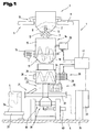
- the manufacturing apparatus 1 is a manufacturing apparatus 1 for processing a material mixture 2, from pretreated plastic flakes 3, in particular plastic foam, but also others Materials e.g. Cork or rubber granules obtained by crushing old parts are shown, to a molding 4.
- the manufacturing apparatus 1 is on the one hand for a gravitational flow of material partly oriented vertically and therefore has at least one arranged at a corresponding height distance 5 from a footprint 6 Silo container 7 on.
- This silo container 7 can, for example, on a roof or ceiling construction 8 of a building 9 to be attached.
- a weighing device 10 for permanent weight detection of the content such as Also to arrange the weight of discharge amounts of the material mixture 2 from the silo 7.
- the delivery of the material mixture 2 from the silo container is carried out by actuation a dispensing flap 11, which at one of the footprint 6 facing the dispensing opening 12 of the silo container 7 is arranged.
- the actuation of the dispensing flap 11 takes place for example, by means of actuating means 13 acted upon by a pressure medium, e.g. Pneumatic cylinder, which are controlled as needed by a control and regulating device.
- a pressure medium e.g. Pneumatic cylinder
- silo container 7 by means of a Conveyor, e.g. a crane system, as needed in a delivery position for a in Direction of the footprint 6 downstream mixing device 14 of the manufacturing device 1 are adjustable.
- the silo containers can also be arranged in a stationary manner be carried out and the derivation of the material mixture via a piping system.
- the mixing device 14 differently procured material fractions bring, which are stored separately in the silo containers 7.
- the mixing device 14 consists of a drum-shaped mixing container 15 with at least a, by means of a drive motor 16 driven mixer rotor 17, consisting of a rotatably mounted rotor shaft 18 having one or more helically extending Spirals 19 is provided.
- the rotor shaft 18 is in opposite directions from an outer periphery to the center of the Misch mattersers 15 wound coil 19 provided.
- the coils 19 are preferred consisting of several segments with different outer diameter formed the mixing of the supplied different material fractions particularly intimately takes place and thus a uniform wetting of the material mixture 2 on the surface with one, during the continuous mixing process in the mixing container 15 via a feeder 20 and nozzles 21, binder 22, e.g. prepolymer thermosetting adhesive is achieved.
- the permanent mixing of the material mixture 2 in the mixing device 14 causes on the one hand the distribution of the binder 22 and on the other hand prevents lumping by adhering the flakes 3 to each other and adhering them to the binder 22 provided flakes 3 on the wall of the mixing container 15 and the mixer rotor 17th
- a Nachmischvorraum 24 is provided, which is filled by the mixing device 14 with the material mixture 2 becomes. On the one hand, this causes a continuous mixing process of the material mixture 2 and on the other hand, a flow of material for trouble-free loading of the metering device 23 with the material mixture 2.
- a mixing chamber 25 forming a housing 26 is direct placed on the metering device 23.
- a helical shaft 27 rotatably mounted and by means of a drive motor 28, in particular a variable speed electric motor 29, driven, wherein a rotation axis 30 of the spiral shaft 27 is arranged in a plane parallel to the footprint 6 level.
- the post-mixing device 24 is the metering device 23 in the direction downstream of the gravity-related material flow.
- the metering device 23 takes place a deflection of the material flow in a direction parallel to the footprint 6 direction a connected to the metering device 23 tubular filling valve 31st
- the filling fitting 31 is opposite and aligned with this one aligned Supply line 32 to the metering device 23 for supplying an air flow a compressed air generator 33 and / or pressure accumulator 34 is arranged.
- the dosing device 23 and the filling fitting 31 thus form the relevant components of a mold filling 35 for filling a mold part 36 with the according to the specifications for Form part 4 recycled and provided amount of material by means of the air flow in the mold part 36 is conveyed.
- a plurality of mold part molds 36 are on a rotary table conveyor 37 are arranged and by means of this for filling in a filling position provided on a timely basis. This is when using a corresponding number of molding parts 36 despite the required reaction and conditioning time for the molding 4 and thus residence time in the mold part 36 reaches a high output of moldings 4.
- the change of the molding parts 36 requires a cyclic coupling and uncoupling of the filling valve 31 as shown in the embodiment, the entire mold filling device 35, So filling valve 31, metering device 23 and supply line 32 and also on the Metering device 23 directly patch mixing device 24 on a linear and in a plane parallel to the footprint 6 in a corresponding guide arrangement 38 movable transport carriage 39 is arranged.
- a drive 40 e.g. Pneumatic cylinder, electric spindle drive, etc.
- the transport carriage 39 is accordingly the stored in a control and / or control device 41 manufacturing program operated.
- the rotary table conveyor 37 is provided with corresponding anchoring means for the molding parts 36 and has corresponding rotary distributor with a fixed Network connected supply lines for steam, compressed air and electric power as well as for Control and data signal exchange on.
- control and data signal exchange with the control and regulation device 41 of the manufacturing device 1 is thus possible via line connections as well as a wireless Communication device can certainly apply.
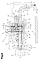
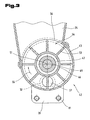
- FIGS. 2 and 3 show in detail the mold filling device 35, consisting of the metering device 23 and downstream in the conveying direction of the material mixture 2 filling fitting 31 and the metering device 23 upstream supply line 32 shown.
- the metering device 23 is formed by a housing 42 of a cylindrical shell part 43 and this laterally delimiting, mutually parallel wall plates 44 and a vane wheel 45 arranged rotatably therein.
- the vane wheel 45 has a cylindrical race 46 with a hub 47 and is on a stub axle 48th a drive shaft 49 arranged non-rotatably in a at least one of the wall disks 44 provided bearing assembly 50 is mounted.
- a rotation axis 51 is perpendicular to a wall disc 42 receiving level.
- the vane wheel is driven 45 from one, drive-connected to the drive shaft 49 rotary drive 52, e.g. one variable speed electric motor 53, the line connected to the control and / or control device 41 is.
- the race 46 outstanding in the circumferential direction, are evenly over distributed circumferentially radially projecting wings 53 arranged. These form delivery chambers 54 between the race 46 and the shell part 43 and between the opposing ones Wall plates 44.
- a number of same volume Images for filling with the material mixture 2 formed according to a predetermined direction of rotation according to - arrow 55 - in a circular path starting from an inlet opening 56 in the casing part 43 is moved.
- the footprint 6 facing lower portion of the housing 42 are coaxial arranged in the opposite wall disks 44 through openings 57 to each other.
- comprehensive connecting flanges 58 is now on the one hand the supply line 32 for the supply of air flow from the compressed air generator 33rd and / or the pressure accumulator and on the other hand, the filling fitting 31 attached.
- the filling fitting 31 and further of the mold part 36 is now the material mixture 2 from each of a number of filled delivery chambers 54, from the receiving volume of a Delivery chamber 54 and the corresponding total material volume for the given Form part 4 is predetermined, by promotion with the air flow according to - arrow 59 - from the Compressed air generator 33 and / or the pressure accumulator 34 supplied and thus a mold cavity 60 of the mold part 36 filled.
- the compressed air generator 33 is in a preferred embodiment, a Roots blower 61 with a controllable via the control and / or control device 41 in its speed Drive motor 62 is formed. Furthermore, to control the air flow in the supply line 32, a control flap 63, by means of an actuating means 64, a flow control of Air flow accordingly in the control and / or control device 41 predetermined parameters causes.
- the filling fitting 31 for conveying the material mixture 2 from the metering device 23rd into the mold cavity 60 of the mold part 36 is by a, preferably a square Internal cross-section exhibiting, profile tube 65 formed via the connecting flange 58 with the housing 42 and the wall plate 44 is detachably connected. Over a large part of one Length 66, the profile tube 65 a via hinges 67 hinged lid 68 with a cutout 69 is covered openable. In the closed position, the lid 68 is detachable Locking means 70 fixed. This is a rapid opening of the cutout 69 of the profile tube 65 possible to remove any buildup and residue of the material mixture 2 or in principle to be able to carry out a cleaning of the entire filling valve 31.
- a connection sleeve 75 with a compressed air connection provided on the periodically a purge air flow for cleaning the filling valve 31 is introduced, in particular in the connection area in the filling valve 31 or on the mold part 36 adhering residues to eliminate and blow out.
- a Outlet opening 77 of the pipe socket 76 is covered with an air-permeable filter element 78, whereby a pressure reduction after a blow-out or after reaching the complete filling of the mold cavity 60 in the filling fitting 31 can be done.
- a filling operation of the mold part 36 and the mold cavity 60 is carried out accordingly predetermined parameter via regulation of the speed of the vane wheel 45 and the Air flow, regulated according to pressure and volume, by the variable speed drive of the Compressed air generator 33 and position of the control flap 63.
- the filling process is by means of of the level sensor 73, wherein in particular as a sensor element 72 optical fiber elements suitable - but also other capacitive or inductive sensors are quite possible, monitored, and the filling process via feedback of the level sensor 73, as soon as a material backlog is found in the filling valve 31, interrupted.
- both the metering device 23 as well as the air flow the compressed air generator 33 with the control flap 63 are reproducible values for the Molded part 36 according to the requirements of the molding 4 volume to be supplied of the material mixture 2 guaranteed.
- This high quality moldings 4 can be achieved. It is also essential that by the air flow in the promotion of the material mixture 2 in the mold cavity 60 no influence on the filling of the delivery chambers 54 of the metering device 23 occurs.
- the metering device 23 with the filling valve 31 and the supply line 32 on the adjustable transport carriages 39 e.g. on parallel Guide rods 80, in a guide assembly 81 in parallel to the footprint 6 Directed adjustable adjustable.
- a drive of the guide carriage 39 takes place, for example by means of a pneumatic cylinder 82 through which a corresponding adjustment and thus exemption of the mold filling device 35 from the mold part 36 when changing an already filled to be filled mold part mold 36 is achieved.
- FIG. 4 is a portion of a turntable 84 of the rotary table conveyor 37, with the essentially of a Formoberteil 85 and a mold base 86 existing mold part 36 shown.
- positioning means 87 e.g. Positioning pins 88
- the between the turntable 84 and the mold base 86 are disposed in position on the turntable 84 held.
- coupling means 89 e.g. Quick clamping elements in the form of clamping jaws 90 etc., actuated by pneumatic cylinder 91 and counter receptacles 92 is a positionally accurate Quick adjustment of the molded part mold 36, in particular its lower mold part 86, on the turntable 84 reached.
- This position on the turntable 84 also ensures the exact docking of the filling fitting 31st to the mold part 36 for the filling of the mold cavity 60 with the material mixture second
- the mold part 36 has other facilities for the treatment of the molding 4, e.g. a modular manner in a receptacle 97 of the mold part 36, in particular of the upper mold part 85 arranged separating and / or lowering device 98 on.
- these on-demand applicable facilities are in the direction of Mold cavity 60 and thus in the molded part 4 separating knife 99 and / or Einsenkstkov 100 etc. adjustable whereby multiple post-processing of the mold parts 4 is saved.
- Such separating and / or Einsenkvoriquesen 98 may, as already mentioned modular be formed functional units, consisting of a guide assembly 101 for the linear Adjustability of the separating knife 99 or punch 100 and provided with a Linear drive 102, e.g. a pneumatic cylinder 103 or alternatively an electromotive Spindle drive, or other known from the prior art drives.
- a Linear drive 102 e.g. a pneumatic cylinder 103 or alternatively an electromotive Spindle drive, or other known from the prior art drives.
- both separating cuts along a parting plane 104 for example, to form separate molded parts, as well as Depressions etc. executable.
- the execution of Divided cuts the cutting blade 104 opposite in a wall portion of the mold part 36 an adapted to the shape of the separating knife 104 elastically deformable stop element 105 provided in a groove-shaped recess 106 whereby a counter knife is not required is and the separation process of the molding 4 by the deformation of the stop element 105 takes place.
- Indentations are often made in such a way that from these outgoing one the molding 4 crossing perforations is created, if necessary, according to a persisting core the intended use of the molded part 4 simple and without costly To be able to remove post-processing. This is often for type-specific adaptations such as. Cable glands or mechanical elements to be attached are provided to various applications for the component 4 e.g. Body part, trim part etc. to be able to cover and thus limit the otherwise required variety of mold parts 36.
- FIG. 5 shows the molding 4 in the mold part 36 during the conditioning time, ie immediately before the removal of the finished molding 4 from the mold part 36th
- FIG. 6 shows in a diagram to the possible course of a pressure level "P” or the delivery volume “V” for during the filling process for filling the mold cavity 60 with the material mixture 2 via the filling fitting 31 supplied air flow, according to arrow 107 as a function of the filling time "T".
- the molded part 4 is a plate-shaped in the illustrated embodiment with edge lands 108 and a centric, e.g. circular, depression 109 provided molding 4, e.g. a cladding element etc.
- edge web 108 In the region of the edge web 108 is to achieve a corresponding strength or rigidity a higher material density, equivalent to a denser structure of the flakes 3, such as this indicated schematically by the hatching provided.
- inventive manufacturing device 1 and the claimed Method also for the processing of further material mixtures, e.g. Rubber granules, Cork granules, etc. and any mixtures thereof, is provided to moldings 4, such as Also, the described molding 4 is not limited to a material mixture of plastic flakes is.
- FIGS. 1, 2, 3; 4; 5, 6 shown embodiments of the subject form independent, inventive solutions.
- the relevant invention Tasks and solutions are the detailed descriptions of these figures too remove.
Landscapes
- Engineering & Computer Science (AREA)
- Mechanical Engineering (AREA)
- Environmental & Geological Engineering (AREA)
- Processing And Handling Of Plastics And Other Materials For Molding In General (AREA)
- Casting Or Compression Moulding Of Plastics Or The Like (AREA)
Applications Claiming Priority (2)
| Application Number | Priority Date | Filing Date | Title |
|---|---|---|---|
| AT0052404A AT500271B1 (de) | 2004-03-25 | 2004-03-25 | Vorrichtung und verfahren zur herstellung eines formteils und formteilform |
| AT5242004 | 2004-03-25 |
Publications (2)
| Publication Number | Publication Date |
|---|---|
| EP1579972A2 true EP1579972A2 (fr) | 2005-09-28 |
| EP1579972A3 EP1579972A3 (fr) | 2006-04-12 |
Family
ID=34842261
Family Applications (1)
| Application Number | Title | Priority Date | Filing Date |
|---|---|---|---|
| EP20050006121 Withdrawn EP1579972A3 (fr) | 2004-03-25 | 2005-03-21 | Dispositif, procédé et moule pour la production d'un objet. |
Country Status (2)
| Country | Link |
|---|---|
| EP (1) | EP1579972A3 (fr) |
| AT (1) | AT500271B1 (fr) |
Cited By (9)
| Publication number | Priority date | Publication date | Assignee | Title |
|---|---|---|---|---|
| WO2007049973A3 (fr) * | 2005-10-28 | 2010-08-26 | Ekornes Asa | Moule de moulage au rebond |
| CN107599291A (zh) * | 2017-10-24 | 2018-01-19 | 重庆宏立至信汽车部件制造有限公司 | 汽车座椅坐垫双硬度发泡模具 |
| AT519381A2 (de) * | 2016-11-24 | 2018-06-15 | Fill Gmbh | Verfahren zur Herstellung eines Formkörpers |
| CN108819048A (zh) * | 2018-07-25 | 2018-11-16 | 天津中车风电叶片工程有限公司 | 一种风电叶片模具翻转角度监测装置 |
| CN110186278A (zh) * | 2019-06-24 | 2019-08-30 | 北京航天环境工程有限公司 | 一种回转窑加料系统及应用 |
| US11141914B2 (en) * | 2016-07-21 | 2021-10-12 | Genesis Dimensions, LLC | Three-dimensional printing system |
| WO2022053350A1 (fr) * | 2020-09-08 | 2022-03-17 | Siegfried Hofmann Gmbh | Système de production d'au moins une partie moulée en mousse de particules |
| CN118046516A (zh) * | 2024-03-05 | 2024-05-17 | 扬州群发光芯科技有限公司 | 一种全聚合物波导器件制造装置 |
| CN120056479A (zh) * | 2025-03-12 | 2025-05-30 | 世泰仕塑料有限公司 | 重型卡车轻量化保温顶盖成型工艺 |
Families Citing this family (4)
| Publication number | Priority date | Publication date | Assignee | Title |
|---|---|---|---|---|
| DE102014117332A1 (de) | 2014-11-26 | 2016-06-02 | Kurtz Gmbh | Verfahren und Vorrichtung zum Herstellen von Partikelschaumstoffteilen |
| CN108437260B (zh) * | 2018-04-28 | 2023-10-13 | 合诚技术股份有限公司 | 一种热塑性弹性体充油设备 |
| DE102019127708A1 (de) * | 2019-10-15 | 2021-04-15 | Kurtz Gmbh | Verfahren und Vorrichtung zum Sortieren und/oder Abmessen der Menge von Schaumstoffpartikeln |
| DE102019215878B4 (de) * | 2019-10-15 | 2023-11-30 | Adidas Ag | Verfahren und Vorrichtung zum Sortieren und/oder Abmessen der Menge von Schaumstoffpartikeln |
Family Cites Families (12)
| Publication number | Priority date | Publication date | Assignee | Title |
|---|---|---|---|---|
| DE3135258A1 (de) * | 1981-09-05 | 1982-10-21 | Daimler-Benz Ag, 7000 Stuttgart | "verfahren zum herstellen von guss- oder fliesspressteilen mit durchbruechen" |
| US4608213A (en) * | 1983-11-04 | 1986-08-26 | Ikeda Bussan Co., Ltd. | Method and mold apparatus for molding a padding member |
| DE3408434A1 (de) * | 1984-03-08 | 1985-09-12 | Hans 5428 Nastätten Erlenbach | Vorrichtung zum herstellen von formlingen aus weichschaum-kunststoff |
| US4818451A (en) * | 1986-04-02 | 1989-04-04 | Mitsubishi Yuka Badische Co., Ltd. | Method of preparing a foamed molded article and blow-filling gun apparatus for use therein |
| AT406606B (de) * | 1988-07-14 | 2000-07-25 | Greiner Schaumstoffwerk | Formteil aus schaumstoffplatten |
| US5252270A (en) * | 1990-12-20 | 1993-10-12 | Basf Aktiengesellschaft | Method of forming foam moldings having varied density regions |
| DE4237239A1 (de) * | 1992-11-04 | 1994-05-05 | Teubert Maschinenbau Gmbh | Schaumstofformkörper, Verfahren zu seiner Herstellung sowie Vorrichtung zur Durchführung des Verfahrens |
| DE59408842D1 (de) * | 1993-11-29 | 1999-11-25 | Greiner & Soehne C A | Formteil aus Kunststoffschaum sowie Verfahren und Vorrichtung zu dessen Herstellung |
| DE19932619A1 (de) * | 1999-07-13 | 2001-01-18 | Basf Ag | Verfahren zur Herstellung von Schaumstoffplatten |
| DE19934459C2 (de) * | 1999-07-27 | 2001-05-31 | Coperion Waeschle Gmbh & Co Kg | Zellenradschleuse |
| ATA11932000A (de) * | 2000-07-11 | 2005-04-15 | Greiner Perfoam Gmbh | Verfahren zur herstellung von schaumstoffprodukten |
| DE10311245A1 (de) * | 2003-03-14 | 2004-09-30 | Greiner Perfoam Ges.m.b.H. | Akustikteil aus Verbundschaumstoff |
-
2004
- 2004-03-25 AT AT0052404A patent/AT500271B1/de not_active IP Right Cessation
-
2005
- 2005-03-21 EP EP20050006121 patent/EP1579972A3/fr not_active Withdrawn
Cited By (13)
| Publication number | Priority date | Publication date | Assignee | Title |
|---|---|---|---|---|
| WO2007049973A3 (fr) * | 2005-10-28 | 2010-08-26 | Ekornes Asa | Moule de moulage au rebond |
| US11919234B2 (en) * | 2016-07-21 | 2024-03-05 | Gannett Peak Partners Llc | Three-dimensional printing system with at least one positioning system and at least one end effector |
| US11141914B2 (en) * | 2016-07-21 | 2021-10-12 | Genesis Dimensions, LLC | Three-dimensional printing system |
| US20220024129A1 (en) * | 2016-07-21 | 2022-01-27 | Genesis Dimensions Llc | Three-dimensional printing system |
| AT519381A2 (de) * | 2016-11-24 | 2018-06-15 | Fill Gmbh | Verfahren zur Herstellung eines Formkörpers |
| CN107599291A (zh) * | 2017-10-24 | 2018-01-19 | 重庆宏立至信汽车部件制造有限公司 | 汽车座椅坐垫双硬度发泡模具 |
| CN108819048A (zh) * | 2018-07-25 | 2018-11-16 | 天津中车风电叶片工程有限公司 | 一种风电叶片模具翻转角度监测装置 |
| CN108819048B (zh) * | 2018-07-25 | 2024-04-05 | 天津中车风电叶片工程有限公司 | 一种风电叶片模具翻转角度监测装置 |
| CN110186278A (zh) * | 2019-06-24 | 2019-08-30 | 北京航天环境工程有限公司 | 一种回转窑加料系统及应用 |
| WO2022053350A1 (fr) * | 2020-09-08 | 2022-03-17 | Siegfried Hofmann Gmbh | Système de production d'au moins une partie moulée en mousse de particules |
| CN116472155A (zh) * | 2020-09-08 | 2023-07-21 | 西格弗里德霍夫曼有限公司 | 用于生产至少一个颗粒泡沫成型部件的系统 |
| CN118046516A (zh) * | 2024-03-05 | 2024-05-17 | 扬州群发光芯科技有限公司 | 一种全聚合物波导器件制造装置 |
| CN120056479A (zh) * | 2025-03-12 | 2025-05-30 | 世泰仕塑料有限公司 | 重型卡车轻量化保温顶盖成型工艺 |
Also Published As
| Publication number | Publication date |
|---|---|
| EP1579972A3 (fr) | 2006-04-12 |
| AT500271B1 (de) | 2008-02-15 |
| AT500271A1 (de) | 2005-11-15 |
Similar Documents
| Publication | Publication Date | Title |
|---|---|---|
| EP1305151B1 (fr) | Procede de fabrication d'articles en mousse | |
| EP2564946B1 (fr) | Procédé de nettoyage de dispositifs de dosage servant au remplissage de dispositifs (par exemple installation d'extrusion, machines de moulage par injection ou analogues) avec des produits en vrac (pellets, copeaux, granulés, poudres, flocons, grains, farine ou analogues) et dispositif de réalisation d'un procédé de ce type et commande pour le nettoyage d'un dispositif de dosage de ce type | |
| EP0657266B2 (fr) | Procédé et appareil pour la production d'une pièce moulée en matière plastique mousse | |
| AT500271B1 (de) | Vorrichtung und verfahren zur herstellung eines formteils und formteilform | |
| DE102017114841B4 (de) | Vorrichtung und Verfahren zur Extrusion von thermo-mechanisch verformbaren granulatförmigen Materialien | |
| EP3849765B1 (fr) | Procédé et dispositif de fabrication de panneaux de pierre artificielle | |
| EP2447047A1 (fr) | Dispositif de traitement de poudre pour un dispositif de fabrication d'un objet tridimensionnel et dispositif de fabrication d'un objet tridimensionnel | |
| EP1990170A2 (fr) | Procédé et dispositif de fabrication d'un élément de formage | |
| CH663569A5 (de) | Beschickungseinrichtung zum zufuehren von kunststoffgranulat in eine spritzgiesseinheit. | |
| DE2924317C2 (de) | Zweistufige Strangpreßvorrichtung für thermoplastische Formmassen, insbesondere für pulverförmige Kunststoffe | |
| DE2334796C2 (de) | Verfahren und Vorrichtung zum Herstellen eines Rohres aus Beton o.dgl. | |
| EP4168168B1 (fr) | Silo de mélange pour matériau en vrac, installation de production dotée d'un tel silo de mélange, et procédé de fonctionnement d'un tel silo de mélange | |
| DE2759878C2 (de) | Vorrichtung zur Verarbeitung von polymerem Material, insbesondere von festem und viskosem Kunststoff | |
| DE102017001093A1 (de) | Entgasen bei der Extrusion von Kunststoffen mit Filterscheiben aus Sintermetall | |
| DE102019205147A1 (de) | Verfahren zur Entleerung einer Vorrichtung zur Herstellung von Granulaten oder Extrudaten | |
| DE4000571C1 (fr) | ||
| DE4208284C1 (fr) | ||
| WO2025125374A1 (fr) | Séchage de matériau pour fabrication additive | |
| WO2012072275A1 (fr) | Dispositif et procédé de fabrication d'agglomérats de polymère | |
| DE102019203284A1 (de) | Vorrichtung zur Aufbereitung von thermoplastischem Restpulver | |
| DE4236344C2 (de) | Vorrichtung zum Konditionieren von wiederverwertbarem, gemahlenem Kunststoffmaterial | |
| WO1997032716A1 (fr) | Dispositif d'alimentation en masses a comprimer pour machines a produire des comprimes | |
| DE3736022A1 (de) | Vorrichtung zum herstellen von formteilen aus einem zu kunststoff, insbesondere schaumkunststoff, ausreagierenden, fliessfaehigen reaktionsgemisch aus fliessfaehigen reaktionskomponenten | |
| DE102019205148A1 (de) | Vorrichtung zur Herstellung von Granulaten oder Extrudaten | |
| DE102018005898A1 (de) | Verfahren zum Mischen von Fasern oder Spänen mit Bindemittel |
Legal Events
| Date | Code | Title | Description |
|---|---|---|---|
| PUAI | Public reference made under article 153(3) epc to a published international application that has entered the european phase |
Free format text: ORIGINAL CODE: 0009012 |
|
| AK | Designated contracting states |
Kind code of ref document: A2 Designated state(s): AT BE BG CH CY CZ DE DK EE ES FI FR GB GR HU IE IS IT LI LT LU MC NL PL PT RO SE SI SK TR |
|
| AX | Request for extension of the european patent |
Extension state: AL BA HR LV MK YU |
|
| PUAL | Search report despatched |
Free format text: ORIGINAL CODE: 0009013 |
|
| AK | Designated contracting states |
Kind code of ref document: A3 Designated state(s): AT BE BG CH CY CZ DE DK EE ES FI FR GB GR HU IE IS IT LI LT LU MC NL PL PT RO SE SI SK TR |
|
| AX | Request for extension of the european patent |
Extension state: AL BA HR LV MK YU |
|
| RTI1 | Title (correction) |
Free format text: APPARATUS, PROCESS AND MOULD FOR PRODUCING A PART. |
|
| 17P | Request for examination filed |
Effective date: 20060607 |
|
| AKX | Designation fees paid |
Designated state(s): AT BE BG CH CY CZ DE DK EE ES FI FR GB GR HU IE IS IT LI LT LU MC NL PL PT RO SE SI SK TR |
|
| 17Q | First examination report despatched |
Effective date: 20100108 |
|
| STAA | Information on the status of an ep patent application or granted ep patent |
Free format text: STATUS: THE APPLICATION IS DEEMED TO BE WITHDRAWN |
|
| 18D | Application deemed to be withdrawn |
Effective date: 20100519 |