EP1580054A2 - Store à enrouleur avec égalisation d'enroulage intégrée - Google Patents
Store à enrouleur avec égalisation d'enroulage intégrée Download PDFInfo
- Publication number
- EP1580054A2 EP1580054A2 EP05004609A EP05004609A EP1580054A2 EP 1580054 A2 EP1580054 A2 EP 1580054A2 EP 05004609 A EP05004609 A EP 05004609A EP 05004609 A EP05004609 A EP 05004609A EP 1580054 A2 EP1580054 A2 EP 1580054A2
- Authority
- EP
- European Patent Office
- Prior art keywords
- roller blind
- winding shaft
- edge
- window roller
- blind according
- Prior art date
- Legal status (The legal status is an assumption and is not a legal conclusion. Google has not performed a legal analysis and makes no representation as to the accuracy of the status listed.)
- Withdrawn
Links
- 238000004804 winding Methods 0.000 title claims abstract description 94
- 230000001154 acute effect Effects 0.000 claims abstract description 9
- 239000004744 fabric Substances 0.000 claims abstract description 5
- 230000003014 reinforcing effect Effects 0.000 claims description 24
- 239000000853 adhesive Substances 0.000 claims description 10
- 230000001070 adhesive effect Effects 0.000 claims description 10
- 230000000284 resting effect Effects 0.000 claims 1
- 239000000463 material Substances 0.000 description 9
- 238000005096 rolling process Methods 0.000 description 4
- 238000000034 method Methods 0.000 description 3
- 238000013459 approach Methods 0.000 description 2
- 230000006835 compression Effects 0.000 description 2
- 238000007906 compression Methods 0.000 description 2
- 241001212149 Cathetus Species 0.000 description 1
- 229910000831 Steel Inorganic materials 0.000 description 1
- 238000004026 adhesive bonding Methods 0.000 description 1
- 230000002411 adverse Effects 0.000 description 1
- 230000037237 body shape Effects 0.000 description 1
- 230000001419 dependent effect Effects 0.000 description 1
- 238000011161 development Methods 0.000 description 1
- 230000018109 developmental process Effects 0.000 description 1
- 238000005516 engineering process Methods 0.000 description 1
- 230000002349 favourable effect Effects 0.000 description 1
- 230000009191 jumping Effects 0.000 description 1
- 238000012986 modification Methods 0.000 description 1
- 230000004048 modification Effects 0.000 description 1
- 230000002787 reinforcement Effects 0.000 description 1
- 230000006641 stabilisation Effects 0.000 description 1
- 238000011105 stabilization Methods 0.000 description 1
- 239000010959 steel Substances 0.000 description 1
- 239000003351 stiffener Substances 0.000 description 1
- 230000008719 thickening Effects 0.000 description 1
- 230000007704 transition Effects 0.000 description 1
- 230000037303 wrinkles Effects 0.000 description 1
Images

Classifications
-
- B—PERFORMING OPERATIONS; TRANSPORTING
- B60—VEHICLES IN GENERAL
- B60J—WINDOWS, WINDSCREENS, NON-FIXED ROOFS, DOORS, OR SIMILAR DEVICES FOR VEHICLES; REMOVABLE EXTERNAL PROTECTIVE COVERINGS SPECIALLY ADAPTED FOR VEHICLES
- B60J1/00—Windows; Windscreens; Accessories therefor
- B60J1/20—Accessories, e.g. wind deflectors, blinds
- B60J1/2011—Blinds; curtains or screens reducing heat or light intensity
- B60J1/2013—Roller blinds
- B60J1/2036—Roller blinds characterised by structural elements
- B60J1/2041—Blind sheets, e.g. shape of sheets, reinforcements in sheets, materials therefor
-
- B—PERFORMING OPERATIONS; TRANSPORTING
- B60—VEHICLES IN GENERAL
- B60B—VEHICLE WHEELS; CASTORS; AXLES FOR WHEELS OR CASTORS; INCREASING WHEEL ADHESION
- B60B1/00—Spoked wheels; Spokes thereof
-
- B—PERFORMING OPERATIONS; TRANSPORTING
- B60—VEHICLES IN GENERAL
- B60J—WINDOWS, WINDSCREENS, NON-FIXED ROOFS, DOORS, OR SIMILAR DEVICES FOR VEHICLES; REMOVABLE EXTERNAL PROTECTIVE COVERINGS SPECIALLY ADAPTED FOR VEHICLES
- B60J1/00—Windows; Windscreens; Accessories therefor
- B60J1/20—Accessories, e.g. wind deflectors, blinds
- B60J1/2011—Blinds; curtains or screens reducing heat or light intensity
- B60J1/2013—Roller blinds
- B60J1/2066—Arrangement of blinds in vehicles
- B60J1/2086—Arrangement of blinds in vehicles specially adapted for openable windows, e.g. side window
Definitions
- Passenger cars usually feature in the rear body area via further side windows.
- These side windows can be mounted either directly in the body or they are part of rear side doors. As far as windows in side doors are concerned, these are divided again, in an approximate trapezoidal Part and a triangular part.
- the trapezoidal Part stems from the fact that the side window in this area is lowered to the window to be able to open.
- the top edge of the side window is set usually made up of a substantially straight section and a curved section together to one To avoid jumping into the trick-shaped area. Indeed can the upper edge of the quadrangular part in the first Approximation to be considered straight. Due to the body shape however, the course of this section is not parallel to the lower edge. With the side window lowered this has the consequence that the top edge of the disc is still visible in the front end of the window slot, while she dives clearly down in the back.
- roller blind shaft below the lower edge of the window it is arranged to be at the top of the window runs parallel.
- Such an arrangement is generally available however, the space inside a door opposite.
- the designer is forced to roll the blind to accommodate parallel to the lower edge.
- This arrangement conditionally in the area towards the front end of the vehicle a longer vertical extension of the roller blind than in the area to the rear. When winding up, that's why more material rolled up in the area of the front edge of the roller blind be considered in the area of the trailing edge.
- the new window blind is as in the state of Technique the roller blind with the additional piece for generating the conical hub in one piece.
- the roller blind sits from a developable from the winding shaft section and a permanent remaining on the winding shaft Section together.
- the permanent on the winding shaft remaining section is separated by a dividing line, a Base edge and two side edges limited. This results an approximate trapezoidal shape, where the base edge, which is shorter than the dividing line, in a very sharp Angle to the dividing line runs.
- One of the two side edges extends approximately at right angles to the dividing line, while the other side edge is at an acute angle runs, which is greater than the acute angle between the dividing line and the base edge.
- a reinforcing strip is provided, the starting from the base edge and parallel to the first side edge runs. Because of this shape, the in itself cylindrical winding shaft along the base edge reproducible be connected with the roller blind exactly. It results an edge on which the winding shaft are aligned can. In addition, the winding shaft is in this way over a relatively long piece already from the beginning with the winding shaft connected, so that tilting during winding of the compensating piece are excluded.
- the unwound from the winding shaft section of Roller blind is made from one end edge and two side edges and the already mentioned dividing line.
- the end edge runs at an acute angle to the dividing line, causing the roller blind is longer in the area of the first side edge as in the area of the second side edge.
- the required diameter ratio at the winding shaft that is necessary so that at the end of the winding process the end edge of the roller blind parallel to the winding shaft or at a desired angle to the angle shaft runs, is achieved when the reinforcing strip a Having a length equal to the height of a triangle, whose base is the base edge and whose one side is from the extension of the first side edge and the other Side is the extension of the second side edge.
- the mentioned height is perpendicular to the base edge, what in Generally with the extension of the first side edge is equal, i. this imaginary triangle represents a right-angled or approximately right-angled triangle in which one catheter has the base edge and the other Kathete is the extension of the first side edge.
- the depth of the recess is between 1 and 15 mm, preferably at about 8 mm.
- the return whose width is the width of the reinforcing strip corresponds, cut a little way.
- the width of the incision is between 1 to 10 mm, preferably around the 3 mm and also has about this depth.
- the Width of the reinforcing strip is in the range between 10 mm and 60 mm, this width being determined by the length of the Winding shaft directs.
- the section remaining permanently on the winding shaft is preferably with stripes or sections with glued to the winding shaft. This saves adhesive and the risk of trapped air later in use in case of temperature fluctuations can cause problems avoided.
- strip-shaped adhesive areas extend expediently on the one hand parallel to the dividing line and on the other hand parallel to the base edge or in the return area parallel to its edge, in the same direction shows as the base edge, as they put out of this one Section forms.
- the reinforcing strip is also adhesive Strip equipped, so by all means the compensation section over the entire length of the base edge cohesively connected to the winding shaft.
- the width of the respective strip-shaped area is smaller than the circumference of the winding shaft.
- the reinforcing strip can be integral with the shade be cut. He can also as a separate Strip be executed. In any case, is expediently the reinforcing strip in the area of the base edge materially connected to the main part of the compensation piece. The other end, which is towards the dividing line shows, remains free against it, so that it wound up can align freely and no wrinkles occur due to compression.
- the second side edge can be about as straight edge of go through the dividing line to the base edge.
- the second side edge perform.
- the length of this extension corresponds to the width of the adhesive strip. From there out follows the second side edge of the edge of the adhesive Stripe, at about a quarter to a third of the Width of the roller blind over a concave curved line in the otherwise straight base edge to pass. hereby assembly is easier because it is not necessary roll up blind material over the entire length.
- the roller blind is advantageously made of a in Essentially non-stretchable knitted fabrics.
- a knitted fabric is limp and can be used in a small amount without wrinkling the area are sheared. It is under shear one Offset of the end edge of the roller blind opposite the dividing line in the direction parallel to the dividing line.
- Figure 1 illustrates the broken cut off rear area a car.
- the figure illustrates a Look at the right inside, which is not illustrated left inside is mirror image.
- the Presentation is simplified, insofar as, for example, internal structures the body like stiffeners, fasteners not shown because their representation for understanding the invention is not required.
- the illustrated body section 1 includes Roof 2, from the side of a B-pillar 3 to a not illustrated floor group leads. A corresponding B-pillar would be on the left-hand side of the vehicle to think.
- the roof 2 goes to its trailing edge a tailgate 4 over, in the usual way at the Lower edge of the roof 2 is hinged.
- a rear window 5 is housed in the tailgate 4, in the tailgate 4, in the tailgate 4, a rear window 5 is housed.
- a moving window 12 which in the usual way, for example. Electric is to move up and down to open the window 11.
- foot areas 15 and 16 of the floor group are located between the two rear side doors 7 .
- the gap between the upper edge of the rear seat back 14th and the inner contour of the tailgate 4 is replaced by a hat rack 17 closed when opening the tailgate 4 in known manner is pivoted upward.
- a Trunk available Below the parcel shelf 17 and behind the rear seat back 14 is a Trunk available.
- the located in the side door 7 window 11 is of a lower straight edge 18 and a substantially straight upper edge 19 and two side edges 20 and 21 limited.
- the upper edge 19 extends below, as shown an acute angle to the lower edge 18, i. the distance between the upper edge and the lower edge 18 is greater in the area of the front side edge 21 than in Area of the rear side edge 20.
- Between these edges 18, 19, 20, 21 of the window 11 may be a roller blind 22, as shown to be stretched.
- the roller blind 22 runs through a slot in the lower window reveal.
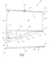
- the roller blind 22 belongs to a side window roller blind 23, whose for the Understanding the invention essential parts shown in Figure 2 are.
- the side window roller 23 is a manually operated window blind.
- the roller blind 22 is a section of a roller blind blank 24.
- the roller blind blank 24 is made the section 22, which can be clamped in front of the window 11 Part, and a section 25 together, whose exact structure is described below.
- In the retracted Condition are the roller blind blanks 22 and 24 on wound up the winding shaft 26.
- the winding shaft 26 contains in her Inside a spring motor 27.
- the spring motor 27 is one end at 28 connected to the tubular winding shaft 26, while the other end of the spring motor on a pin 29th is fixed, the rotation in the interior of the door 7 below the lower edge of the window 18 is received.
- the winding shaft 26 has a cylindrical Pin 31, which is rotatably mounted in a bearing block, the at the appropriate distance also below the bottom Window edge 18 is located.
- the winding shaft 26 is how mentions a cylindrical steel tube and it runs in mounted state within the door 7, i. between the Exterior skin of door and door inner panel parallel to the lower edge 18 of the window 11th
- the roller blind section 22 is from a first side edge 32, an approximately parallel second Side edge 33, a top or end edge 34 and a Dividing line 35 limited.
- the top or end edge 34 is with an excerpt profile 36 stiffening this edge, which has approximately in the middle of a hook 37, either with the upper edge of the window 12 of the window 11 to is hooked or in a special eyelet on the inside the side door 7 is to hang.
- the pull-out profile 36 is straight and thus approximates in its course the upper edge 19 of the side window eleventh
- the trapezoidal shape of the window 11 is also section 22, i. the extendable part of the Roller blind 22 trapezoidal, in the sense that the dividing line 35, at which section 22 passes into section 25, at an acute angle to the top or end edge 34 or in the extension profile 36 runs.
- the integrally in the section 22 passing section 25 serves the purpose of ensuring that if the Section 22 is wound on the winding shaft 26, the Extensions profile 36 exactly parallel to the lower edge 18 of the Window 11 runs so as to close the slot, through the roller blind 22 during extension from the Door interior is pulled out.
- This gap can be the same Be cleft, by the well in a known manner, the retractable Side window disappears when opening the window.
- the section 25 thus ultimately serves as a winding compensation to make sure that in the area of the side edge 32 more material is wound on the winding shaft 26 than in the area of the side edge 33.
- the winding compensation forming portion 25 of the Blank 24 is from a first side edge 38, a its opposite second side edge 39, the Dividing line 35 and a base edge 41 limited.
- the base edge 41 runs at an acute angle to the dividing line 35, as shown so that both the base edge 41 and also the top edge 34 in the same direction on the dividing line 35 to converge.
- the side edge 38 is a straight edge without Jump into the side edge 32 passes.
- the side edge 32 may have a slight kink at 42 to open this way to approach a section of a ring.
- the base edge 41 is significantly shorter as it corresponds to the length of the dividing line 35.
- the length the base edge 41 is about half to one third the length of the dividing line 35.
- the base edge 41 starts at a corner 42, which is located in the inner area between the Extensions of the two side edges 32 and 33 is located and leads straight from there to an incision 43.
- the base edge 41 forms a straight Return 44, whose terminal edge parallel to the extension the longer piece of the base edge 41 runs.
- the base edge 41 jumps approx. 8 mm back.
- the width of the incision 43 is between 2 mm and 10 mm preferably about 4 mm while the depth of the Incision is about 4 mm long.
- the second side edge 39 begins at the corner 42 and begins with a concave section 45, which at 46 in a straight piece, which is approximately parallel to the dividing line 35, but at a short distance to a corner 47 runs. From here, the side edge 39 goes with a Straight section 48 directly into the side edge 33rd above.
- the reinforcing strip 49 is about 40 mm wide, measured in the direction parallel to the base edge 41.
- section 25 approaches of the blank 24 about a triangle.
- This triangle is about a right triangle, of which one is a catheter the dividing line 35 is at which the two sections 22 and 25 in one piece into each other.
- the other catheter is the extension of the first side edge 38, while the Hypotenuse is a dashed line 51, on the one hand begins in the area where the dividing line 35 the second Side edge 33 cuts and the other by the Corner 42 goes, at the base edge 41 in the second side edge 39 passes.
- the dashed extension 52 of Side edge 38 and hypotenuse 51 intersect at one Tip 53.
- the distance of this tip 53 from the edge of the recess 44 corresponds to the length of the rectangular Reinforcement strip 49, measured from the edge 44 up to its the dividing line 35 adjacent edge 54th
- the blank 24 thus obtained is in the region of the compensating section 25 with the outer surface of the winding shaft 26 materially connected. This runs along the base edge 41 between the recess 43 and the corner 42 the page facing the viewer a klebdress equipped Strip 55. Its width is low on the distance of the base edge 41 from the parting line 35.
- a another adhesive strip 56 is located on the viewer facing side of the reinforcing strip 49 between the recess 43 and the side edge 38. The width of the strip 56 corresponds to the width of the Stsammlungs 55.
- Another on the viewer's side existing adhesive strip 57 follows Dividing line 35 and it extends from parting line 35 in the section 25.
- the width of the strip 56 corresponds the length of the straight portion 48 of the side edge 39.
- the winding shaft 46 is on the adhesive Strip 55 launched, in such a way that its longitudinal axis lies parallel to the base edge 41. It will be as possible glued close to the base edge 41, so they initially not sticking to the strip during gluing 56 attached or touched, because in this area the material is doubly, what the clean bonding of the Streaks past strip 55 following notch 43 would.
- the winding shaft 26 on the viewer's side on the section 25 rolled in the direction of the parting line 35. there it moves along a ring, its center right of the side edges 33 and 48 lies. During the Rolling it runs on the reinforcing strip 49, while they are on the flat plane at the other end Rolling pad. At the end of the rolling motion is the Winding shaft with its axis parallel to the parting line 35th and the strip 57 fixes the roll permanently on the Winding shaft 26.
- a winding shaft achieved, which is no longer cylindrical as the winding shaft 26, but an approximate slender cone that where the side edge is 48, the diameter of the original Winding shaft 26 has, while in the field of Side edge 38 corresponding to the number of turns of the winding shaft through the material of the blank 24 in diameter is enlarged.
- the difference in diameter of the generated cone-shaped Aufwickelköpers, consisting of the winding shaft 26 and the Section 25, is chosen so that at the end of the winding process the top or end edge 34 with the pull-out profile 36 at a predetermined desired angle the axis of the winding shaft 26 extends. In the described If the edge should lie parallel to the lower edge of the window 18, around the existing extract slot or gap largely close.
- the invention essentially relates to the type and Way like a slender conical bobbin for a Roller blind can be produced. This was the embodiment explained using a manual roller blind. It understands However, without further ado that also an electric Operation is possible.
- the upper edge runs the roller blind in the extended state under a pointed Angle to the axis of the winding shaft.
- To wind up the winding shaft has a conical shape to have.
- the conical shape is achieved by the Roller blind continues in a trapezoidal section, the permanently on the cylindrical winding shaft remains. This Section is placed next to one edge by one Reinforced reinforcing strip in thickness.
Landscapes
- Engineering & Computer Science (AREA)
- Mechanical Engineering (AREA)
- Operating, Guiding And Securing Of Roll- Type Closing Members (AREA)
- Winding Of Webs (AREA)
Applications Claiming Priority (2)
| Application Number | Priority Date | Filing Date | Title |
|---|---|---|---|
| DE200410015396 DE102004015396B4 (de) | 2004-03-26 | 2004-03-26 | Fensterrollo mit integriertem Wickelausgleich |
| DE102004015396 | 2004-03-26 |
Publications (2)
| Publication Number | Publication Date |
|---|---|
| EP1580054A2 true EP1580054A2 (fr) | 2005-09-28 |
| EP1580054A3 EP1580054A3 (fr) | 2008-05-14 |
Family
ID=34854104
Family Applications (1)
| Application Number | Title | Priority Date | Filing Date |
|---|---|---|---|
| EP05004609A Withdrawn EP1580054A3 (fr) | 2004-03-26 | 2005-03-03 | Store à enrouleur avec égalisation d'enroulage intégrée |
Country Status (2)
| Country | Link |
|---|---|
| EP (1) | EP1580054A3 (fr) |
| DE (1) | DE102004015396B4 (fr) |
Citations (1)
| Publication number | Priority date | Publication date | Assignee | Title |
|---|---|---|---|---|
| EP0111270A1 (fr) | 1982-12-03 | 1984-06-20 | Hüppe GmbH | Store enroulable |
Family Cites Families (4)
| Publication number | Priority date | Publication date | Assignee | Title |
|---|---|---|---|---|
| FR2750158B1 (fr) * | 1996-06-20 | 1998-11-27 | Farnier Et Penin Snc | Store a enrouleur a rattrapage conique |
| DE29709524U1 (de) * | 1997-06-02 | 1998-11-05 | Hüppe Form Sonnenschutzsysteme GmbH, 26133 Oldenburg | Rollo, insbesondere zum Abschirmen von Fenstern und Kfz-Scheiben |
| US6047762A (en) * | 1998-03-20 | 2000-04-11 | Prince Corporation | Shade control for a vehicle window |
| DE10204331B4 (de) * | 2002-02-01 | 2005-10-27 | Bos Gmbh & Co. Kg | Rolloartige Anordnung mit längsgeteilter Wickelwelle |
-
2004
- 2004-03-26 DE DE200410015396 patent/DE102004015396B4/de not_active Expired - Fee Related
-
2005
- 2005-03-03 EP EP05004609A patent/EP1580054A3/fr not_active Withdrawn
Patent Citations (1)
| Publication number | Priority date | Publication date | Assignee | Title |
|---|---|---|---|---|
| EP0111270A1 (fr) | 1982-12-03 | 1984-06-20 | Hüppe GmbH | Store enroulable |
Also Published As
| Publication number | Publication date |
|---|---|
| DE102004015396B4 (de) | 2006-04-20 |
| DE102004015396A1 (de) | 2005-11-10 |
| EP1580054A3 (fr) | 2008-05-14 |
Similar Documents
| Publication | Publication Date | Title |
|---|---|---|
| EP1588880B1 (fr) | Store à enrouleur pour système de toit coulissant | |
| EP1612070B1 (fr) | Store à rouleau de fenêtre pour vitres de véhicule courbées ou non rectangulaires | |
| EP1209013B1 (fr) | Vitre avec store à enrouleur attaché | |
| DE69204994T2 (de) | Aufrollbare Markise von geringem Gewicht. | |
| DE19616448C5 (de) | Windschott für ein Cabriolet | |
| DE102007045414A1 (de) | Seitenfensterrollo mit Einlaufhilfe | |
| EP1393939A2 (fr) | Store enroulable pour protection solaire | |
| DE102005038373B4 (de) | Sonnenschutzvorrichtung | |
| DE10064513A1 (de) | Rollo | |
| DE19902289B4 (de) | Spoiler für ein Fahrzeug | |
| DE2815821C2 (de) | Blendschutz für Fahrzeuge | |
| DE60124162T2 (de) | Verdunkelungseinrichtung für Fenster und/oder für Fahrzeugöffnung mit Anwendung von Stangen, und korrespondierendes Fahrzeug | |
| DE102004030262B3 (de) | Rollo mit konischer Wickelwelle | |
| EP1398190B1 (fr) | Dispositif pare-soleil à store enrouleur pour une fenêtre d'automobile | |
| DE102014003440B3 (de) | Laderaumabdeckung für ein Fahrzeug | |
| DE10215678B4 (de) | Beschattungseinrichtung für eine Scheibe | |
| DE19603099A1 (de) | Rollo, insbesondere für ein Fondseitenfenster eines Kraftfahrzeuges | |
| DE202004015857U1 (de) | Leicht laufendes Sonnenschutzrollo für Glasdächer | |
| EP1652705B1 (fr) | Store enroulé également | |
| DE3536189A1 (de) | Rollo-vorrichtung fuer fenster | |
| DE102004015396B4 (de) | Fensterrollo mit integriertem Wickelausgleich | |
| DE60213903T2 (de) | Vorhang mit Spiralfeder | |
| DE60027071T2 (de) | Rollo mit Handgriff und indexiertem Haken, und korrespondierendes Verfahren zur Herstellung | |
| WO2006032243A1 (fr) | Dispositif de protection d'une vitre d'un vehicule automobile | |
| DE602005006027T2 (de) | Veränderbare Verdunkelungsvorrichtung für ein Motorfahrzeug, und korrespondierendes Fahrzeug |
Legal Events
| Date | Code | Title | Description |
|---|---|---|---|
| PUAI | Public reference made under article 153(3) epc to a published international application that has entered the european phase |
Free format text: ORIGINAL CODE: 0009012 |
|
| AK | Designated contracting states |
Kind code of ref document: A2 Designated state(s): AT BE BG CH CY CZ DE DK EE ES FI FR GB GR HU IE IS IT LI LT LU MC NL PL PT RO SE SI SK TR |
|
| AX | Request for extension of the european patent |
Extension state: AL BA HR LV MK YU |
|
| RIN1 | Information on inventor provided before grant (corrected) |
Inventor name: HANSEN, MELF Inventor name: BELIBEL, BOUAZIZ Inventor name: KALAESZ, GAEBOR Inventor name: SHARIFI-KHOZANI, MOSTAFA |
|
| PUAL | Search report despatched |
Free format text: ORIGINAL CODE: 0009013 |
|
| AK | Designated contracting states |
Kind code of ref document: A3 Designated state(s): AT BE BG CH CY CZ DE DK EE ES FI FR GB GR HU IE IS IT LI LT LU MC NL PL PT RO SE SI SK TR |
|
| AX | Request for extension of the european patent |
Extension state: AL BA HR LV MK YU |
|
| AKX | Designation fees paid | ||
| STAA | Information on the status of an ep patent application or granted ep patent |
Free format text: STATUS: THE APPLICATION IS DEEMED TO BE WITHDRAWN |
|
| 18D | Application deemed to be withdrawn |
Effective date: 20081114 |
|
| REG | Reference to a national code |
Ref country code: DE Ref legal event code: 8566 |