EP1580123A2 - System zur Druckluftaufbereitung - Google Patents
System zur Druckluftaufbereitung Download PDFInfo
- Publication number
- EP1580123A2 EP1580123A2 EP05004580A EP05004580A EP1580123A2 EP 1580123 A2 EP1580123 A2 EP 1580123A2 EP 05004580 A EP05004580 A EP 05004580A EP 05004580 A EP05004580 A EP 05004580A EP 1580123 A2 EP1580123 A2 EP 1580123A2
- Authority
- EP
- European Patent Office
- Prior art keywords
- heat exchanger
- air
- compressed air
- ohx
- air conditioning
- Prior art date
- Legal status (The legal status is an assumption and is not a legal conclusion. Google has not performed a legal analysis and makes no representation as to the accuracy of the status listed.)
- Granted
Links
Images



Classifications
-
- B—PERFORMING OPERATIONS; TRANSPORTING
- B64—AIRCRAFT; AVIATION; COSMONAUTICS
- B64D—EQUIPMENT FOR FITTING IN OR TO AIRCRAFT; FLIGHT SUITS; PARACHUTES; ARRANGEMENT OR MOUNTING OF POWER PLANTS OR PROPULSION TRANSMISSIONS IN AIRCRAFT
- B64D37/00—Arrangements in connection with fuel supply for power plant
- B64D37/32—Safety measures not otherwise provided for, e.g. preventing explosive conditions
-
- B—PERFORMING OPERATIONS; TRANSPORTING
- B64—AIRCRAFT; AVIATION; COSMONAUTICS
- B64D—EQUIPMENT FOR FITTING IN OR TO AIRCRAFT; FLIGHT SUITS; PARACHUTES; ARRANGEMENT OR MOUNTING OF POWER PLANTS OR PROPULSION TRANSMISSIONS IN AIRCRAFT
- B64D13/00—Arrangements or adaptations of air-treatment apparatus for aircraft crew or passengers, or freight space
- B64D13/06—Arrangements or adaptations of air-treatment apparatus for aircraft crew or passengers, or freight space the air being conditioned
- B64D2013/0603—Environmental Control Systems
- B64D2013/0677—Environmental Control Systems comprising on board oxygen generator systems
-
- Y—GENERAL TAGGING OF NEW TECHNOLOGICAL DEVELOPMENTS; GENERAL TAGGING OF CROSS-SECTIONAL TECHNOLOGIES SPANNING OVER SEVERAL SECTIONS OF THE IPC; TECHNICAL SUBJECTS COVERED BY FORMER USPC CROSS-REFERENCE ART COLLECTIONS [XRACs] AND DIGESTS
- Y02—TECHNOLOGIES OR APPLICATIONS FOR MITIGATION OR ADAPTATION AGAINST CLIMATE CHANGE
- Y02T—CLIMATE CHANGE MITIGATION TECHNOLOGIES RELATED TO TRANSPORTATION
- Y02T50/00—Aeronautics or air transport
- Y02T50/40—Weight reduction
Definitions
- the invention relates to a system for compressed air treatment with a heat exchanger (System heat exchanger), the compressed air side inlet side with a compressed air source communicates with and on the discharge side with a system or Device is connected, which is to be supplied with cooled compressed air, and with at least a heat exchanger (air conditioning heat exchanger), the compressed air side inlet side with a compressed air source in communication and the compressed air side outlet side with other components of an aircraft air conditioning in conjunction stands.
- a heat exchanger Air conditioning heat exchanger
- the invention relates to an architecture for compressed air treatment, which for the operation (supply) of oxygen and nitrogen generation equipment needed in airplanes.
- OBOGS molecular sieve filling materials There are different OBOGS molecular sieve filling materials. All these materials However, it is common that the molecular sieve with cooled Compressed air from approx. 0 ° C to 60 ° C and a relative pressure of approx. 1.4 bar (rel) to 4.0 bar (rel) must be supplied.
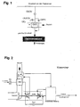
- the state of the art is the OBOGS Supply, by hot compressed air (about 200 ° C) from the compressed air tap system in a special OBOGS heat exchanger is passed. The air is on the required temperature range of about 0 ° C to 60 ° C cooled, as shown in FIG. 1 evident.
- the OBOGS is very rarely in operation, as the likelihood of failure of the Cabin printing is very low due to the built-in redundancies.
- unfavorable composition can be an explosive mixture, which itself or by sparking inflamed.
- EP 1 375 349 A1 describes a device for producing nitrogen which referred to as OBIGGS (On Board Inert Gas Generation System). Comparable to the OBOGS also this OBIGGS is based on molecular sieving technology, but here the oxygen is filtered out. At the outlet of the OBIGG produces a product gas with greatly reduced oxygen content (less than 10%) and a significantly increased nitrogen content. This product gas can now in the Kerosene tanks are headed for the risk of self-ignition of the kerosene air mixture to avoid. Furthermore, the OBIGGS product gas z. B. be routed to cargo holds to minimize the risk of fire.
- OBIGGS On Board Inert Gas Generation System
- the OBIGGS requires a supply of cooled Compressed air from approx. 50 ° C to 90 ° C.
- PSA Pressure Swing Absorption Process
- HFM Hollow Fiber Membrane
- FIG. 1 such a system is shown.
- Fig. 1 shows that the heat exchanger OHX associated with the OBIGGS / OBOGS and the following System heat exchanger is called, on the inlet side with compressed air (bleed air) from the engines is acted upon.
- the inlet pipe is by means of the valve OSOV closable.
- a control valve OBPV is shown, by means of which a bypass line to the system heat exchanger OHX is closed.
- the reference numerals OESOV and OEJ are components of a jet-pump, which promotes of ambient air through the system heat exchanger OHX needed in ground operation becomes.
- the cooled Compressed air is available, which is then fed to the OBIGSS / OBOGS.
- the desired product gas deducted or the destinations in question be supplied.
- the OBIGGS is mostly in operation.
- This task is performed by a system for compressed air preparation with the features of claim 1 or by a method having the features of claim 19 solved.
- the system heat exchanger and the at least an air conditioning heat exchanger via a common inlet to Supply with congestion or ambient air, and that the system heat exchanger on its compressed air outlet side with the compressed air side, with the at least one air conditioning heat exchanger associated line system or with the at least one air conditioning heat exchanger itself over a closable line is connected.
- the system heat exchanger is in the already existing ram air channel of Air conditioning integrated. To cool the system heat exchanger is congestion or Ambient air from the common ram air duct or the air conditioning heat exchanger and the system heat exchanger used.
- one or more system heat exchangers are arranged in the ram air channel.
- the system heat exchanger OHX can on its compressed air side outlet with the compressed air side inlet or outlet of the at least one air conditioning heat exchanger be connected via the closable line. It is preferred if the connection of the compressed air outlet side of the system heat exchanger OHX to the compressed air side outlet of the heat exchanger of the air conditioner, preferred to the outlet side of the compressed air side of the first heat exchanger of the Air conditioning, done.
- the closable conduit may include an open / close valve or a valve by means of whose different flow rates can be adjusted by the line.
- the lockable Line between the compressed air side outlet of the system heat exchanger OHX and the compressed air side outlet of the at least one air conditioning heat exchanger extends and from this line upstream of a valve, by means of of which the conduit is closable, branches off a conduit leading to the system or device that needs to be supplied with cooled compressed air. Consists on the part of Systems or device no compressed air requirement, this line can be closed become.
- a compressed air side is the first and a second air conditioning heat exchanger downstream of this compressed air side provided, wherein the system heat exchanger OHX on its compressed air side Outlet side via the sealable line with the compressed air side on or preferably outlet of the compressed air side first and ram air side preferably second air conditioning heat exchanger is connected.
- the closable line between the outlet side of the system heat exchanger OHX and the compressed air side Outlet of the compressed air side first air conditioning heat exchanger extends and from this line upstream of a valve, by means of which the line can be closed is a line leading to the system or device that with cooled compressed air is to supply.
- the system heat exchanger OHX can ram air side relative to the or the air conditioning heat exchangers be arranged differently.
- system heat exchanger OHX ram air side before or after the ram air side first air conditioning heat exchanger is arranged. Sofem the system heat exchanger OHX and the or the air conditioning heat exchangers are connected in series on the ram air side, can be provided that they cover completely or only partially, so a complete or partial series connection is achieved.
- the ram air side are arranged one behind the other. It can the system heat exchanger OHX on the ram air side after the ram air side first air conditioning heat exchanger and ram air side parallel to another air conditioning heat exchanger, preferably to the primary heat exchanger, i. the compressed air side be arranged first heat exchanger of the air conditioner.
- a ram air inlet flap provided that in its closed position not the ram air side Supply line of the system heat exchanger OHX closes.
- This is a partition is provided, which causes the ram air supply to the system heat exchanger OHX and for the one or the same to this ram air side arranged in parallel Air conditioning heat exchanger is separated.
- the adjustable ram air inlet flap in the closed state closes exclusively the ram-air-side supply line of the or the air conditioning heat exchanger. This can be avoided in heating mode (with the ram air inlet flap closed) too low a ram air throughput This could be attributed to the failure of the blower Fig. 7 will be explained.
- the compressed air inlet line of the system heat exchanger OHX and its Compressed-air outlet pipe to be supplied with the cooled compressed air System or device leads can by means of a lockable bypass line communicate with each other. By opening the bypass line, the Temperature in the system or device in question are regulated.
- the to the compressed air side Inlet of the system heat exchanger OHX leading compressed air supply and leading to the compressed air side inlet of the air conditioning heat exchanger or the Compressed air supply from a common compressed air line from the compressed air tap system branch.
- the compressed air in the compressed air tap system for example provided by the engines or an auxiliary power unit. In consideration comes any compressed air source, such as a compressor.
- compressed air dispensing system is thus not limited to a system in the compressed air from the engines or an auxiliary unit is tapped.
- the compressed air side inlet of the system heat exchanger OHX is connected via a valve with the compressed air supply.
- the valve may be an on / off valve or a valve by means of whose a certain throughput is adjustable.
- the valve can be connected in parallel with the intake valve of the aircraft air conditioning system be.
- the compressed air side inlet of the system heat exchanger OHX with the outlet of the intake valve of the aircraft air conditioning system connected via a line.
- the system heat exchanger OHX supplied with compressed air via the intake valve of the aircraft air conditioning system.
- system heat exchanger OHX on the compressed air side outlet side in conjunction and that is to be supplied with cooled compressed air to an emergency oxygen supply system (OBOGS) and / or a nitrogen production system (OBIGGS) act.
- OOGS emergency oxygen supply system
- OBIGGS nitrogen production system
- the present invention further relates to a method having the features of the claim 19. Thereafter, it is envisaged that in a first mode of operation Compressed air after cooling in the system heat exchanger OHX the system or Device is supplied with the system heat exchanger OHX is in communication and that is to be supplied with cooled compressed air, and that in a second operating mode the compressed air after cooling in the system heat exchanger OHX the compressed air side, with the at least one air conditioning heat exchanger in Connecting line system of the air conditioner or the at least one Air conditioning heat exchanger itself is supplied.
- the compressed air is in the second operating mode after cooling in the system heat exchanger OHX the compressed air side on or Outlet of the at least one air conditioning heat exchanger, preferably supplied to the outlet of the compressed air side first air conditioning heat exchanger becomes.
- system heat exchanger OHX and the at least one air conditioning heat exchanger via a common compressed air line be supplied from the compressed air tap system.
- the aircraft air conditioning system may be required.
- the bypass can be opposite to the Conventional operation will be blended much cooler air when the second Operating mode is set when the compressed air partially or completely in the Bypass around the turbine is to lead.
- valve In the compressed air side inlet line of the system heat exchanger OHX can Be provided valve. In the event that this valve is faulty in the closed position remains, it is provided that the system heat exchanger OHX with compressed air is applied upstream or downstream of the at least one Air conditioning heat exchanger or from the air conditioning heat exchanger itself is removed. Thus, the failure of said valve does not lead to a total failure the systems to be supplied by the system heat exchanger OHX.
- the system heat exchanger OHX and the at least one air conditioning heat exchanger through a common inlet, but acted upon by a separate supply with storage or ambient air be, and that a ram air inlet flap is provided, in their Closed position only the ram-air-side supply line of the air conditioning heat exchanger closes, the ram air inlet flap closed in heating mode so that the storage or ambient air in heating mode only through the system heat exchanger flows.
- a ram air inlet flap is provided, in their Closed position only the ram-air-side supply line of the air conditioning heat exchanger closes, the ram air inlet flap closed in heating mode so that the storage or ambient air in heating mode only through the system heat exchanger flows.
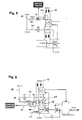
- Fig. 2 shows the typical structure of an aircraft air conditioning system.
- the flow control valve FCV of the air conditioner is hot compressed air from the Engines or an auxiliary unit fed (about 200 ° C and 3 bar). This air is pre-cooled in the preheat exchanger PHX to about 100 ° C and then in a compressor C further compressed. Thereafter, a second cooling of the Compressed air in main heat exchanger SHX to approx. 40 ° C with subsequent dehumidification in a water separation system. After that, the dehumidified air in the Turbine T relaxes while cooling down to about -30 ° C.
- the accumulating at the turbine Shaft power is used to drive the compressor and a blower Promotion of PHX / SHX ram air or ambient air used. From the turbine outlet the air flows through the water separation system and then into a mixing chamber or in the cabin.
- Fig. 2 shows the architecture of an aircraft air conditioning system only by way of example. Independently of the concrete architecture is always a ram air duct in an aircraft air conditioning system with at least one ram air heat exchanger installed there.
- Embodiments comprising one (HX), two (PHX and SHX) or more than two air conditioning heat exchangers.
- Figs. 3 to 5 show embodiments of the invention, which are in the arrangement of the system heat exchanger OHX.
- the closable invention Line between the compressed air outlet side of the system heat exchanger OHX and the compressed air line system of the Aircraft Air Conditioner is in not shown in these drawings.
- the line, not shown, extends in the embodiments of Figs. 3 to 5 between the compressed air side outlet the system heat exchanger OHX and the first heat exchanger on the compressed air side PHX of the air conditioning.
- Fig. 3 shows the integration of the system heat exchanger OHX in the common Stau povertykanal, in which also the air conditioning heat exchangers PHX and SHX are located.
- the OHX is thus in the already existing ram air duct of the air conditioner integrated.
- the architecture of compressed air cooling for the OBOGS / OBIGGS Supply is unchanged the same as already shown in Fig. 1.
- Compressed air from About 200 ° C is the open valve OSOV the system heat exchanger OHX fed.
- ram air from the common ram air inlet channel used by air conditioning and system heat exchanger OHX By means of the Valve OBPV in the bypass line 50 is the compressed air side inlet of the system heat exchanger OHX connected to the compressed air side outlet.
- By corresponding opening of the OBPV can reduce the temperature of the OBOGS / OBIGGS supply air be managed.
- the major advantages of the integration shown in FIG. 3 are the system heat exchanger the weight and space savings due to the omission an OBOGS / OBIGGS ram air channel.
- Another advantage is that the blower of the air cycle machine is arranged such that a jam or Ambient air flow rate not only for the air conditioning heat exchangers PHX, SHX, but also for the system heat exchanger OHX is generated.
- the system heat exchanger OHX with the Air conditioning heat exchangers in series further gives the advantage that the System heat exchanger OHX supplied ram air not useless through the system heat exchanger OHX is performed, but always at least one of the air conditioning heat exchanger flows through.
- Fig. 3 leads to the compressed air side inlet of the system heat exchanger OHX the compressed air supply 60 and to the compressed air side Inlet of the primary heat exchanger PHX the compressed air supply 70, the one of branch off the common compressed air line 80 of the compressed air tap system.
- the arrangement of the system heat exchanger OHX with respect to the or the stagnation air heat exchanger PHX, SHX the air conditioner can vary depending on the conditions and Requirements be different.
- Fig. 6 shows the closable connection line 20 between the compressed air side Outlet side of the system heat exchanger OHX and the discharge side outlet the compressed air side first ram air heat exchanger of the air conditioner (here PHX).
- the open / close valve 22 is arranged, opened by means of the line or can be closed.
- OBOGS / OBIGGS is off (inlet valve closed at OBIGGS / OBOGS, not shown here) then it will OHXSOV and OSOV open, creating an additional heat exchanger for the Air conditioning can be used.
- the OHXOV also provides redundancy regarding the OBOGS / OBIGGS supply elevated. Should the OSOV fail in a closed position, then the System heat exchanger OHX with compressed air from the compressed air side outlet of the PHX be powered by the OHXOV is opened. In an architecture without this connection (see FIG. 3) results in a closed OSOV for the failure of OBOGS / OBIGGS supply.
- FCV and OSOV parallel valves
- connection via the OHXOV leads to another advantage.
- the solution according to the invention also has the following advantages in heating operation on:
- the function of the air conditioner includes cooling and heating. Heating is enabled by opening the TCV the ACM (Air Cycle Machine) (including Cooling turbine) and the ram air heat exchanger SHX at least partially bypassed becomes (Fig. 7). If the achieved heating power is not sufficient, can also an additional and controllable flap at the inlet of the ram air duct available be. By partially closing this flap, the ram air flow rate and thus reduces the heat transfer of the stagnation air heat exchanger (here SHX and PHX) (see Fig. 7).
- the ACM Air Cycle Machine
- SHX stagnation air heat exchanger
- the necessary minimum throughput for the fan is thus the ram air of the system heat exchanger OHX ensured.
- the ram air flap in Heating mode completely closed, resulting in a much higher Heating power of the air conditioner results.
- the delivered in the ram air heat exchanger OHX Heat does not affect the air conditioner when the air side Outlet of the system heat exchanger OHX is disconnected from the air conditioner. If a configuration as shown in Fig. 6 is used, then the OHXOV closed in heating mode.
- Fig. 9 shows an inventive system for compressed air treatment, which largely corresponds to the system explained in FIG. 6, so that corresponding reference is taken.
- a difference arises from the fact that the compressed air side inlet of the system heat exchanger OHX with the outlet of the inlet valve FCV Aircraft air conditioning system is connected via a line.
- the line 70 branches off this line from the line 70, which is located between the outlet of Inlet valve FCV and the compressed air side inlet of the compressed air side first air conditioning heat exchanger PHX extends.
- FIG. 9 In the embodiment of FIG. 9 is different from the embodiment according to FIG. 6, therefore, no separate inlet valve OSOV for the system heat exchanger OHX provided.
- Fig. 10 shows an embodiment of the invention in which the compressor 100 as Compressed air source is used.
- the Compressed air source is not limited to the engines or an auxiliary unit, but includes any means for compressed air generation.
- a compressor If a compressor is used, it can be connected upstream of an aircraft air conditioning system or even part of the air conditioning itself, for example, part be an ACM of the air conditioning.
- the compressor can be driven arbitrarily. Consider, for example a motor driven compressor and / or a compressor with a turbine sitting on a common shaft.
- the compressor can be designed in one or more stages.
- the aforementioned embodiments of the compressed air source apply to the Compressed air supply of at least one air conditioning heat exchanger and / or for those of the system heat exchanger.
- the compressor 100 is at its pressure side with the compressed air side inlet of the heat exchanger HX in conjunction, in the ram air channel is arranged.
- the ram air channel is also the system heat exchanger OHX, with the pressure side of the compressor on its compressed air side Inlet side communicates.
- the compressed air outlet of the system heat exchanger OHX is on the connecting line 20 with the compressed air side Outlet of air conditioning heat exchanger HX in conjunction.
- the shut-off valve 22 is the shut-off valve 22.
- the line 30 is above the bypass line 50, the can be closed by means of the valve OBPV, with the compressed air supply of the OHX in Connection.
- the cooled compressed air is the secondary components the air conditioner or the aircraft cabin or one of these upstream Fed mixing chamber.
Landscapes
- Engineering & Computer Science (AREA)
- Aviation & Aerospace Engineering (AREA)
- Central Air Conditioning (AREA)
Abstract
Description
In der Klimaanlage wird die vom Druckluftzapfsystem kommende Luft entsprechend der anfallenden Kühl- und Heizanforderungen gekühlt, um eine konstante Temperatur in der Kabine zu gewährleisten. Zusätzlich wird der notwendige Frischluftdurchsatz zum Ventilieren der Kabine sichergestellt.
Dieses System regelt den Kabinendruck, indem mittels variabler Ventilposition mehr oder weniger Kabinenluft an die Umgebung zurück strömt.
- Fig. 1:
- OBOGS/OBIGGS-Wärmetauscher OHX zur Kühlung von Druckluft;
- Fig. 2:
- Architektur einer Flugzeugklimaanlage;
- Fig. 3:
- Stauluftkanal der Flugzeugklimaanlage mit integriertem Systemwärmetauscher OHX;
- Fig. 4:
- Anordnung des Systemwärmetauschers OHX im Stauluftkanal;
- Fig. 5:
- Anordnung des Systemwärmetauschers OHX im Stauluftkanal;
- Fig. 6:
- Systemwärmetauscher OHX mit in der Verbindungsleitung zu der Flugzeugklimaanlage befindlichen Ventil OHXOV;
- Fig. 7:
- Klimaanlage mit Stauluftkanaleinlassklappe;
- Fig. 8:
- Getrennter Stauluftkanal mit Stauluftkanaleinlassklappe zum Verschluss der Zuführung der Klimaanlagenwärmetauscher;
- Fig. 9.:
- Architektur gemäß Fig. 6 mit über das FCV mit Druckluft versorgtem Systemwärmetauscher OHX;
- Fig. 10:
- System zur Druckluftaufbereitung mit einem Verdichter als Druckluftquelle.
Claims (24)
- System zur Druckluftaufbereitung mit einem Wärmetauscher (OHX) (Systemwärmetauscher), der druckluftseitig einlassseitig mit einer Druckluftquelle in Verbindung steht und druckluftseitig auslassseitig mit einem System (OBOGS; OBIGGS) oder Gerät in Verbindung steht, das mit gekühlter Druckluft zu versorgen ist, und mit wenigstens einem Wärmetauscher (PHX, SHX) (Klimaanlagenwärmetauscher), der druckluftseitig einlassseitig mit einer Druckluftquelle in Verbindung steht und druckluftseitig auslassseitig mit weiteren Komponenten einer Flugzeugklimaanlage in Verbindung steht,
dadurch gekennzeichnet, dass der Systemwärmetauscher (OHX) und der wenigstens eine Klimaanlagenwärmetauscher (HX, PHX, SHX) über einen gemeinsamen Einlass (10) zur Zufuhr mit Stau- oder Umgebungsluft verfügen, und dass der Systemwärmetauscher (OHX) auf seiner druckluftseitigen Auslassseite mit dem druckluftseitigen, mit dem wenigstens einen Klimaanlagenwärmetauscher (HX, PHX, SHX) in Verbindung stehenden Leitungssystem oder mit dem wenigstens einen Klimaanlagenwärmetauscher selbst über eine verschließbare Leitung (20) verbunden ist. - System nach Anspruch 1, dadurch gekennzeichnet, dass der Systemwärmetauscher (OHX) auf seiner druckluftseitigen Auslassseite mit dem druckluftseitigen Ein- oder Auslass des wenigstens einen Klimaanlagenwärmetauschers (HX, PHX) über die verschließbare Leitung (20) verbunden ist.
- System nach Anspruch 1 oder 2, dadurch gekennzeichnet, dass die verschließbare Leitung (20) ein Auf-/Zu-Ventil (22) oder ein Ventil aufweist, mittels dessen sich unterschiedliche Durchsätze durch die Leitung einstellen lassen.
- System nach einem der vorhergehenden Ansprüche, dadurch gekennzeichnet, dass sich die verschließbare Leitung (20) zwischen dem druckluftseitigen Auslass des Systemwärmetauschers (OHX) und dem druckluftseitigen Auslass des wenigstens einen Klimaanlagenwärmetauschers (HX, PHX) erstreckt und von dieser Leitung (20) stromaufwärts eines Ventils (22), mittels dessen die Leitung (20) verschließbar ist, eine Leitung (30) abzweigt, die zu dem System (OBOGS; OBIGGS) oder Gerät führt, das mit gekühlter Druckluft zu versorgen ist.
- System nach einem der vorhergehenden Ansprüche, dadurch gekennzeichnet, dass ein druckluftseitig erster (PHX) und ein diesem druckluftseitig nachgeschalteter zweiter Klimaanlagenwärmetauscher (SHX) vorgesehen ist und dass der Systemwärmetauscher (OHX) auf seiner druckluftseitigen Auslassseite über die verschließbare Leitung (20) mit dem druckluftseitigen Ein- oder Auslass des druckluftseitig ersten Klimaanlagenwärmetauschers (PHX) verbunden ist.
- System nach Anspruch 5, dadurch gekennzeichnet, dass sich die verschließbare Leitung (20) zwischen dem druckluftseitigen Auslass des Systemwärmetauschers (OHX) und dem druckluftseitigen Auslass des ersten Klimaanlagenwärmetauschers (PHX) erstreckt und von dieser Leitung (20) stromaufwärts des Ventils (22), mittels dessen die Leitung verschließbar ist, eine Leitung (30) abzweigt, die zu dem System (OBOGS; OBIGGS) oder Gerät führt, das mit gekühlter Druckluft zu versorgen ist.
- System nach einem der vorhergehenden Ansprüche, dadurch gekennzeichnet, dass der Systemwärmetauscher (OHX) zu dem oder den Klimaanlagenwärmetauschern (PHX, SHX) stauluftseitig parallel geschaltet ist.
- System nach einem der vorhergehenden Ansprüche, dadurch gekennzeichnet, dass der Systemwärmetauscher (OHX) stauluftseitig vor dem stauluftseitig ersten Klimaanlagenwärmetauscher (SHX) angeordnet ist.
- System nach einem der Ansprüche 1 bis 7, dadurch gekennzeichnet, dass der Systemwärmetauscher (OHX) stauluftseitig nach dem stauluftseitig ersten Klimaanlagenwärmetauscher (SHX) angeordnet ist.
- System nach einem der vorhergehenden Ansprüche, dadurch gekennzeichnet, dass zwei oder mehr Klimaanlagenwärmetauscher (PHX, SHX) vorgesehen sind, die stauluftseitig hintereinander angeordnet sind und dass der Systemwärmetauscher (OHX) stauluftseitig nach dem stauluftseitig ersten Klimaanlagenwärmetauscher (SHX) und stauluftseitig parallel zu einem weiteren Klimaanlagenwärmetauscher (PHX) angeordnet ist.
- System nach einem der vorhergehenden Ansprüche, dadurch gekennzeichnet, dass eine Trennwand (40) vorgesehen ist, die bewirkt, dass die Stauluftzuführung für den Systemwärmetauscher (OHX) sowie für den oder die Klimaanlagenwärmetauscher (PHX, SHX) getrennt (41, 42) erfolgt, und dass eine verstellbare Staulufteinlassklappe vorgesehen ist, die im geschlossenen Zustand ausschließlich die stauluftseitige Zuleitung (42) des oder der Klimaanlagenwärmetauscher (PHX, SHX) verschließt.
- System nach einem der vorhergehenden Ansprüche, dadurch gekennzeichnet, dass die druckluftseitige Einlassleitung des Systemwärmetauschers (OHX) und dessen druckluftseitige Auslassleitung, die zu dem mit der gekühlten Druckluft zu versorgenden System (OBOGS, OBIGGS) oder Gerät führt, mittels einer verschließbaren Bypassleitung (50) miteinander in Verbindung stehen.
- System nach einem der vorhergehenden Ansprüche, dadurch gekennzeichnet, dass die zu dem druckluftseitigen Einlass des Systemwärmetauschers (OHX) führende Druckluftzuführung und die zu dem druckluftseitigen Einlass des oder der Klimaanlagenwärmetauscher (HX, PHX, SHX) führende Druckluftzuführung (60, 70) von einer gemeinsamen Druckluftleitung (80) vom Druckluftzapfsystem abzweigen.
- System nach einem der vorhergehenden Ansprüche, dadurch gekennzeichnet, dass der druckluftseitige Einlass des Systemwärmetauschers (OHX) über ein Ventil (OSOV) mit der Druckluftzuführung verbunden ist.
- System nach Anspruch 14, dadurch gekennzeichnet, dass das Ventil (OSOV) parallel zu dem Einlassventil (FCV) der Flugzeugzeugklimaanlage geschaltet ist.
- System nach einem der vorhergehenden Ansprüche, dadurch gekennzeichnet, dass der druckluftseitige Einlass des Systemwärmetauschers (OHX) mit dem Auslass des Einlassventils (FCV) der Flugzeugzeugklimaanlage über eine Leitung verbunden ist.
- System nach einem der vorhergehenden Ansprüche, dadurch gekennzeichnet, dass es sich bei dem System (OBOGS; OBIGGS) oder Gerät, mit dem der Systemwärmetauscher (OHX) auf der Druckluftseite auslassseitig in Verbindung steht und das mit gekühlter Druckluft zu versorgen ist, um ein Notsauerstoffversorgungssystem (OBOGS) und/oder um ein Stickstofferzeugungssystem (OBIGGS) handelt.
- System nach einem der vorhergehenden Ansprüche, dadurch gekennzeichnet, dass es sich bei der Druckluftquelle um einen ein- oder mehrstufigen Verdichter, vorzugsweise einen motorisch angetriebenen Verdichter handelt.
- Verfahren zum Betrieb eines Systems zur Druckluftaufbereitung mit einem ersten Wärmetauscher (OHX) (Systemwärmetauscher), der druckluftseitig einlassseitig mit einer Druckluftquelle in Verbindung steht und druckluftseitig auslassseitig mit einem System (OBOGS, OBIGGS) oder Gerät in Verbindung steht, das mit gekühlter Druckluft zu versorgen ist, und mit wenigstens einem Wärmetauscher (HX, PHX, SHX) (Klimaanlagenwärmetauscher), der druckluftseitig einlassseitig mit einer Druckluftquelle in Verbindung steht und druckluftseitig auslassseitig mit weiteren Komponenten einer Flugzeugklimaanlage in Verbindung steht,
dadurch gekennzeichnet, dass in einem ersten Betriebsmodus die Druckluft nach der Kühlung in dem Systemwärmetauscher (OHX) dem System (OBOGS; OBIGGS) oder Gerät zugeführt wird, mit dem der Systemwärmetauscher (OHX) in Verbindung steht und das mit gekühlter Druckluft zu versorgen ist, und dass in einem zweiten Betriebsmodus die Druckluft nach der Kühlung in dem Systemwärmetauscher (OHX) dem druckluftseitigen, mit dem wenigstens einen Klimaanlagenwärmetauscher (HX, PHX, SHX) in Verbindung stehenden Leitungssystem oder dem wenigstens einen Klimaanlagenwärmetauscher selbst zugeführt wird. - Verfahren nach Anspruch 19, dadurch gekennzeichnet, dass die Druckluft in dem zweiten Betriebsmodus nach der Kühlung in dem Systemwärmetauscher (OHX) dem druckluftseitigen Ein- oder Auslass des wenigstens einen Klimaanlagenwärmetauschers (HX, PHX) zugeführt wird.
- Verfahren nach Anspruch 19 oder 20, dadurch gekennzeichnet, dass der Systemwärmetauscher (OHX) sowie der wenigstens eine Klimaanlagenwärmetauscher (HX, PHX, SHX) über eine gemeinsame Druckluftleitung (80) aus dem Druckluftzapfsystem versorgt werden.
- Verfahren nach einem der vorhergehenden Ansprüche, dadurch gekennzeichnet, dass das System zur Druckluftaufbereitung eine Flugzeugklimaanlage umfasst, die eine Turbine (T) aufweist, die druckluftseitig mit dem wenigstens einen Klimaanlagenwärmetauscher (PHX, SHX) in Verbindung steht, und dass, wenn die Druckluft teilweise oder vollständig im Bypass um die Turbine (T) geführt wird, der zweite Betriebsmodus eingestellt wird.
- Verfahren nach einem der vorhergehenden Ansprüche, dadurch gekennzeichnet, dass in der druckluftseitigen Einlassleitung (70) des Systemwärmetauschers (OHX) ein Ventil (OSOV) vorgesehen ist, und dass in dem Fall, dass dieses Ventil (OSOV) fehlerhaft in der Schließstellung verbleibt, der Systemwärmetauscher (OHX) mit Druckluft beaufschlagt wird, die stromaufwärts oder stromabwärts des wenigstens einen Klimaanlagenwärmetauschers (PHX) oder aus dem Klimaanlagenwärmetauscher selbst entnommen wird.
- Verfahren nach einem der vorhergehenden Ansprüche, dadurch gekennzeichnet, dass der Systemwärmetauscher (OHX) und der wenigstens eine Klimaanlagenwärmetauscher (PHX, SHX) durch einen gemeinsamen Einlass (10), jedoch mittels einer getrennten Zuführung (41, 42) mit Stau- oder Umgebungsluft beaufschlagt werden, und dass eine Staulufteinlassklappe vorgesehen ist, die in der ihrer Schließstellung ausschließlich die stauluftseitige Zuleitung (42) der Klimaanlagenwärmetauscher (PHX, SHX) verschließt, wobei die Staulufteinlassklappe im Heizbetrieb geschlossen wird, so dass die Stau- oder Umgebungsluft im Heizbetrieb nur durch den Systemwärmetauscher (OHX) strömt.
Applications Claiming Priority (2)
| Application Number | Priority Date | Filing Date | Title |
|---|---|---|---|
| DE102004010366A DE102004010366B4 (de) | 2004-03-03 | 2004-03-03 | System zur Druckluftaufbereitung |
| DE102004010366 | 2004-03-03 |
Publications (3)
| Publication Number | Publication Date |
|---|---|
| EP1580123A2 true EP1580123A2 (de) | 2005-09-28 |
| EP1580123A3 EP1580123A3 (de) | 2005-12-28 |
| EP1580123B1 EP1580123B1 (de) | 2007-01-24 |
Family
ID=34853926
Family Applications (1)
| Application Number | Title | Priority Date | Filing Date |
|---|---|---|---|
| EP05004580A Expired - Lifetime EP1580123B1 (de) | 2004-03-03 | 2005-03-02 | System zur Druckluftaufbereitung |
Country Status (5)
| Country | Link |
|---|---|
| US (1) | US7845188B2 (de) |
| EP (1) | EP1580123B1 (de) |
| CA (1) | CA2499664C (de) |
| DE (2) | DE102004010366B4 (de) |
| ES (1) | ES2281858T3 (de) |
Cited By (2)
| Publication number | Priority date | Publication date | Assignee | Title |
|---|---|---|---|---|
| WO2009141400A2 (de) | 2008-05-21 | 2009-11-26 | Airbus Operations Gmbh | Inertisierungssystem für ein flugzeug |
| EP3552971A3 (de) * | 2018-03-23 | 2020-02-12 | United Technologies Corporation | Antriebssystemkühlungssteuerung |
Families Citing this family (20)
| Publication number | Priority date | Publication date | Assignee | Title |
|---|---|---|---|---|
| DE102004038860A1 (de) * | 2004-08-10 | 2006-02-23 | Airbus Deutschland Gmbh | System zur Erzeugung von Prozessluft |
| US7334422B2 (en) * | 2005-11-29 | 2008-02-26 | Hamilton Sundstrand Corporation | Cabin air conditioning system with liquid cooling for power electronics |
| DE102006016541B4 (de) | 2006-04-07 | 2014-05-22 | Airbus Operations Gmbh | Klimatisierungssystem für Flugzeuge |
| US8079407B2 (en) * | 2006-11-09 | 2011-12-20 | Honeywell International Inc. | Integrated heat exchangers for ECS and OBIGGS applications |
| GB201020783D0 (en) * | 2010-12-08 | 2011-01-19 | Eaton Aerospace Ltd | On board inert gas generation system |
| US20130139521A1 (en) * | 2011-11-29 | 2013-06-06 | Eaton Aerospace Limited | On board inert gas generation system |
| EP3094560A1 (de) * | 2013-12-18 | 2016-11-23 | Carleton Life Support Systems, Inc. | Lufttrocknendes system für obogs |
| US9782714B2 (en) * | 2015-02-09 | 2017-10-10 | The Boeing Company | Stored gas pressure recovery system |
| US9994322B2 (en) * | 2015-02-11 | 2018-06-12 | Hamilton Sundstrand Corporation | Environmental control system utilizing parallel ram heat exchangers |
| US10710730B2 (en) | 2015-04-15 | 2020-07-14 | Honeywell International Inc. | Passive OBOGS temperature supply using conditioned avionics cooling |
| US9789967B2 (en) | 2015-12-16 | 2017-10-17 | Hamilton Sundstrand Corporation | Environmental control system |
| FR3047976B1 (fr) * | 2016-02-18 | 2019-05-03 | Zodiac Aerotechnics | Generateur de gaz d'inertage, et systeme d'inertage d'un reservoir de carburant d'un aeronef mettant en œuvre ledit generateur de gaz d'inertage |
| US11459110B2 (en) | 2016-04-22 | 2022-10-04 | Hamilton Sunstrand Corporation | Environmental control system utilizing two pass secondary heat exchanger and cabin pressure assist |
| EP3249196B1 (de) | 2016-05-26 | 2020-12-02 | Hamilton Sundstrand Corporation | Energiefluss eines fortschrittlichen klimaregelungssystems |
| US11506121B2 (en) * | 2016-05-26 | 2022-11-22 | Hamilton Sundstrand Corporation | Multiple nozzle configurations for a turbine of an environmental control system |
| EP3248880B1 (de) | 2016-05-26 | 2022-03-16 | Hamilton Sundstrand Corporation | Mischen von stau- und zapfluft in einem turbinensystem mit doppeltem eingang |
| US10384785B2 (en) | 2017-02-17 | 2019-08-20 | Hamilton Sundstrand Corporation | Two mode system that provides bleed and outside air or just outside air |
| US10850854B2 (en) * | 2017-06-28 | 2020-12-01 | Hamilton Sunstrand Corporation | Three wheel and simple cycle aircraft environmental control system |
| US11358725B2 (en) | 2017-06-28 | 2022-06-14 | Hamilton Sundstrand Corporation | Three wheel and simple cycle aircraft environmental control system |
| US12528589B2 (en) * | 2022-08-04 | 2026-01-20 | Hamilton Sundstrand Corporation | RAM air cooling power recovery |
Family Cites Families (28)
| Publication number | Priority date | Publication date | Assignee | Title |
|---|---|---|---|---|
| US4378920A (en) * | 1980-07-15 | 1983-04-05 | The Boeing Company | Combustibly inert air supply system and method |
| GB9003033D0 (en) * | 1990-02-10 | 1990-04-11 | Normalair Garrett Ltd | Oxygen-rich gas breathing systems |
| US5214935A (en) * | 1990-02-20 | 1993-06-01 | Allied-Signal Inc. | Fluid conditioning apparatus and system |
| US5086622A (en) * | 1990-08-17 | 1992-02-11 | United Technologies Corporation | Environmental control system condensing cycle |
| US5309731A (en) * | 1991-12-27 | 1994-05-10 | Nippondenso Co., Ltd. | Air conditioning apparatus |
| US5309724A (en) * | 1992-09-16 | 1994-05-10 | Grumman Aerospace Corporation | Switchable heat exchanger configuration for air cycle cooling apparatus |
| US5511385A (en) * | 1994-12-23 | 1996-04-30 | United Technologies Corp. | Independent compartment temperature control for single-pack operation |
| US5704218A (en) * | 1996-04-08 | 1998-01-06 | United Technologies Corporation | Integrated environmental control system |
| US6128909A (en) * | 1998-06-04 | 2000-10-10 | Alliedsignal Inc. | Air cycle environmental control systems with two stage compression and expansion and separate ambient air fan |
| US6250097B1 (en) * | 1999-10-12 | 2001-06-26 | Alliedsignal Inc. | Dual expansion energy recovery (DEER) air cycle system with mid pressure water separation |
| US6491739B1 (en) * | 1999-11-09 | 2002-12-10 | Litton Systems, Inc. | Air separation module using a fast start valve for fast warm up of a permeable membrane air separation module |
| FR2800706B1 (fr) * | 1999-11-10 | 2002-01-18 | Dassault Aviat | Procede et dispositif d'alimentation d'une entree d'air frais de la cabine d'un aeronef propulse par au moins un moteur a reaction |
| DE10036443A1 (de) * | 2000-07-26 | 2002-04-04 | Liebherr Aerospace Gmbh | Klimatisierungssystem für Flugzeuge |
| DE10047623C1 (de) * | 2000-09-26 | 2002-05-23 | Liebherr Aerospace Gmbh | Klimatisierungssystem für Flugzeuge |
| US6845630B2 (en) * | 2001-02-16 | 2005-01-25 | Hamilton Sundstrand Corporation | Electric power and cooling system for an aircraft |
| EP1273514B1 (de) * | 2001-07-05 | 2005-12-07 | Shimadzu Corporation | Flugzeug-Klimaanlage |
| GB0118292D0 (en) * | 2001-07-27 | 2001-09-19 | Honeywell Normalair Garrett | Air cycle cooling system |
| DE10139483B4 (de) * | 2001-08-10 | 2005-06-23 | Liebherr-Aerospace Lindenberg Gmbh | Klimatisierungssystem |
| DE10201426B8 (de) * | 2002-01-16 | 2004-09-02 | Liebherr-Aerospace Lindenberg Gmbh | Klimatisierungssystem |
| JP2003240375A (ja) * | 2002-02-20 | 2003-08-27 | Sumitomo Precision Prod Co Ltd | エアサイクル式空気調和装置 |
| US6997970B2 (en) * | 2002-06-25 | 2006-02-14 | Carleton Life Support Systems, Inc. | Oxygen/inert gas generator |
| US20040025507A1 (en) * | 2002-08-02 | 2004-02-12 | Honeywell International Inc. | Turbo compressor for use in OBIGGS application |
| US7048231B2 (en) * | 2002-10-04 | 2006-05-23 | Shaw Aero Devices, Inc. | Increasing the performance of aircraft on-board inert gas generating systems by turbocharging |
| US6739359B2 (en) * | 2002-10-04 | 2004-05-25 | Shaw Aero Devices, Inc. | On-board inert gas generating system optimization by pressure scheduling |
| US6913636B2 (en) * | 2002-12-17 | 2005-07-05 | Hamilton Sundstrand Corporation | Low power nitrogen enriched air generation system |
| WO2004099579A2 (en) * | 2003-03-07 | 2004-11-18 | Shaw Aero Devices, Inc. | Cooling system for an on-board inert gas generating system |
| US6942183B2 (en) * | 2003-09-22 | 2005-09-13 | Hamilton Sundstrand | Air cycle air conditioning with adaptive ram heat exchanger |
| US7081153B2 (en) * | 2003-12-02 | 2006-07-25 | Honeywell International Inc. | Gas generating system and method for inerting aircraft fuel tanks |
-
2004
- 2004-03-03 DE DE102004010366A patent/DE102004010366B4/de not_active Expired - Fee Related
-
2005
- 2005-03-02 DE DE502005000338T patent/DE502005000338D1/de not_active Expired - Lifetime
- 2005-03-02 US US11/071,546 patent/US7845188B2/en active Active
- 2005-03-02 ES ES05004580T patent/ES2281858T3/es not_active Expired - Lifetime
- 2005-03-02 EP EP05004580A patent/EP1580123B1/de not_active Expired - Lifetime
- 2005-03-03 CA CA2499664A patent/CA2499664C/en not_active Expired - Fee Related
Cited By (11)
| Publication number | Priority date | Publication date | Assignee | Title |
|---|---|---|---|---|
| WO2009141400A2 (de) | 2008-05-21 | 2009-11-26 | Airbus Operations Gmbh | Inertisierungssystem für ein flugzeug |
| WO2009141400A3 (de) * | 2008-05-21 | 2010-04-29 | Airbus Operations Gmbh | Inertisierungssystem für ein flugzeug |
| US8500878B2 (en) | 2008-05-21 | 2013-08-06 | Airbus Operations Gmbh | Inerting system for an aircraft |
| EP3552971A3 (de) * | 2018-03-23 | 2020-02-12 | United Technologies Corporation | Antriebssystemkühlungssteuerung |
| US11299279B2 (en) | 2018-03-23 | 2022-04-12 | Raytheon Technologies Corporation | Chilled working fluid generation and separation for an aircraft |
| US11305879B2 (en) | 2018-03-23 | 2022-04-19 | Raytheon Technologies Corporation | Propulsion system cooling control |
| US11542016B2 (en) | 2018-03-23 | 2023-01-03 | Raytheon Technologies Corporation | Cryogenic cooling system for an aircraft |
| US12291338B2 (en) | 2018-03-23 | 2025-05-06 | Rtx Corporation | Chilled working fluid generation and separation for an aircraft |
| US12337974B2 (en) | 2018-03-23 | 2025-06-24 | Rtx Corporation | Propulsion system cooling control |
| US12351318B2 (en) | 2018-03-23 | 2025-07-08 | Rtx Corporation | Cryogenic cooling system for an aircraft |
| US12358630B2 (en) | 2018-03-23 | 2025-07-15 | Rtx Corporation | Cryogenic cooling system for an aircraft |
Also Published As
| Publication number | Publication date |
|---|---|
| US20050235659A1 (en) | 2005-10-27 |
| EP1580123B1 (de) | 2007-01-24 |
| CA2499664A1 (en) | 2005-09-03 |
| DE102004010366B4 (de) | 2008-03-27 |
| CA2499664C (en) | 2012-11-27 |
| ES2281858T3 (es) | 2007-10-01 |
| DE102004010366A1 (de) | 2005-09-22 |
| EP1580123A3 (de) | 2005-12-28 |
| US7845188B2 (en) | 2010-12-07 |
| DE502005000338D1 (de) | 2007-03-15 |
Similar Documents
| Publication | Publication Date | Title |
|---|---|---|
| EP1580123B1 (de) | System zur Druckluftaufbereitung | |
| EP1752377B1 (de) | Verfahren zum Betreiben eines Flugzeugsystems | |
| EP2282935B1 (de) | Inertisierungssystem für ein flugzeug | |
| EP1439123B1 (de) | Klimatisierungssystem und Verfahren zum Betrieb | |
| DE3330556C2 (de) | ||
| EP1190946B1 (de) | Klimatisierungssystem für Flugzeuge | |
| EP0648671B1 (de) | Kabinenumluftsystem zur Klimatisierung von Rumpfeinheiten eines Passagierflugzeuges | |
| EP2285678B1 (de) | System zur ventilation eines flugzeugbereichs | |
| EP1880939B1 (de) | Flugzeugklimaanlage und Verfahren zum Betreiben einer Flugzeugklimaanlage | |
| DE102006016541B4 (de) | Klimatisierungssystem für Flugzeuge | |
| DE10139483B4 (de) | Klimatisierungssystem | |
| DE10361658B4 (de) | Vorrichtung und Verfahren zum Beheizen einer Flugzeugkabine | |
| DE102007032306A1 (de) | Klimatisierungssystem für Flugzeugkabinen | |
| DE102004039669A1 (de) | Kühlung von Luft in einem Flugzeug | |
| DE102006007286A1 (de) | System zur Verbesserung der Luftqualität in einer Druckkabine eines Flugzeuges | |
| DE102008032088A1 (de) | System zur Kühlung eines Flugzeugbereichs zur Verbindung mit einem flugzeugexternen Luftaggregat | |
| DE102004017879B4 (de) | System zur Luftaufbereitung | |
| DE102013008620A1 (de) | Flugzeugkühlsystem und Verfahren zum Betreiben eines Flugzeugkühlsystems | |
| DE60207642T2 (de) | Flugzeug-Klimaanlage | |
| DE102006014572B4 (de) | Vorrichtung und Verfahren zur Luftverteilung in einem Frachtflugzeug | |
| DE102004038860A1 (de) | System zur Erzeugung von Prozessluft | |
| DE102004026647B4 (de) | Einrichtung zur Luftzerlegung | |
| DE102007004366A1 (de) | Klimatisierungssystem | |
| DE102015216247A1 (de) | Flugzeugklimaanlage zur Verbindung mit einem flugzeugexternen Lufterzeugungsaggregat |
Legal Events
| Date | Code | Title | Description |
|---|---|---|---|
| PUAI | Public reference made under article 153(3) epc to a published international application that has entered the european phase |
Free format text: ORIGINAL CODE: 0009012 |
|
| AK | Designated contracting states |
Kind code of ref document: A2 Designated state(s): AT BE BG CH CY CZ DE DK EE ES FI FR GB GR HU IE IS IT LI LT LU MC NL PL PT RO SE SI SK TR |
|
| AX | Request for extension of the european patent |
Extension state: AL BA HR LV MK YU |
|
| PUAL | Search report despatched |
Free format text: ORIGINAL CODE: 0009013 |
|
| AK | Designated contracting states |
Kind code of ref document: A3 Designated state(s): AT BE BG CH CY CZ DE DK EE ES FI FR GB GR HU IE IS IT LI LT LU MC NL PL PT RO SE SI SK TR |
|
| AX | Request for extension of the european patent |
Extension state: AL BA HR LV MK YU |
|
| 17P | Request for examination filed |
Effective date: 20060323 |
|
| GRAP | Despatch of communication of intention to grant a patent |
Free format text: ORIGINAL CODE: EPIDOSNIGR1 |
|
| AKX | Designation fees paid |
Designated state(s): DE ES FR GB IT |
|
| GRAS | Grant fee paid |
Free format text: ORIGINAL CODE: EPIDOSNIGR3 |
|
| GRAA | (expected) grant |
Free format text: ORIGINAL CODE: 0009210 |
|
| AK | Designated contracting states |
Kind code of ref document: B1 Designated state(s): DE ES FR GB IT |
|
| REG | Reference to a national code |
Ref country code: GB Ref legal event code: FG4D Free format text: NOT ENGLISH |
|
| REF | Corresponds to: |
Ref document number: 502005000338 Country of ref document: DE Date of ref document: 20070315 Kind code of ref document: P |
|
| GBT | Gb: translation of ep patent filed (gb section 77(6)(a)/1977) |
Effective date: 20070418 |
|
| ET | Fr: translation filed | ||
| REG | Reference to a national code |
Ref country code: ES Ref legal event code: FG2A Ref document number: 2281858 Country of ref document: ES Kind code of ref document: T3 |
|
| PLBE | No opposition filed within time limit |
Free format text: ORIGINAL CODE: 0009261 |
|
| STAA | Information on the status of an ep patent application or granted ep patent |
Free format text: STATUS: NO OPPOSITION FILED WITHIN TIME LIMIT |
|
| 26N | No opposition filed |
Effective date: 20071025 |
|
| REG | Reference to a national code |
Ref country code: FR Ref legal event code: PLFP Year of fee payment: 12 |
|
| PGFP | Annual fee paid to national office [announced via postgrant information from national office to epo] |
Ref country code: ES Payment date: 20160322 Year of fee payment: 12 |
|
| PGFP | Annual fee paid to national office [announced via postgrant information from national office to epo] |
Ref country code: GB Payment date: 20160321 Year of fee payment: 12 |
|
| PGFP | Annual fee paid to national office [announced via postgrant information from national office to epo] |
Ref country code: IT Payment date: 20160331 Year of fee payment: 12 |
|
| REG | Reference to a national code |
Ref country code: FR Ref legal event code: PLFP Year of fee payment: 13 |
|
| GBPC | Gb: european patent ceased through non-payment of renewal fee |
Effective date: 20170302 |
|
| PG25 | Lapsed in a contracting state [announced via postgrant information from national office to epo] |
Ref country code: GB Free format text: LAPSE BECAUSE OF NON-PAYMENT OF DUE FEES Effective date: 20170302 Ref country code: IT Free format text: LAPSE BECAUSE OF NON-PAYMENT OF DUE FEES Effective date: 20170302 |
|
| REG | Reference to a national code |
Ref country code: FR Ref legal event code: PLFP Year of fee payment: 14 |
|
| REG | Reference to a national code |
Ref country code: ES Ref legal event code: FD2A Effective date: 20180704 |
|
| PG25 | Lapsed in a contracting state [announced via postgrant information from national office to epo] |
Ref country code: ES Free format text: LAPSE BECAUSE OF NON-PAYMENT OF DUE FEES Effective date: 20170303 |
|
| PGFP | Annual fee paid to national office [announced via postgrant information from national office to epo] |
Ref country code: FR Payment date: 20240321 Year of fee payment: 20 |
|
| PGFP | Annual fee paid to national office [announced via postgrant information from national office to epo] |
Ref country code: DE Payment date: 20240403 Year of fee payment: 20 |
|
| REG | Reference to a national code |
Ref country code: DE Ref legal event code: R071 Ref document number: 502005000338 Country of ref document: DE |