EP1580133A2 - Procédé et dispositif de déchargement de produit en vrac - Google Patents
Procédé et dispositif de déchargement de produit en vrac Download PDFInfo
- Publication number
- EP1580133A2 EP1580133A2 EP04017777A EP04017777A EP1580133A2 EP 1580133 A2 EP1580133 A2 EP 1580133A2 EP 04017777 A EP04017777 A EP 04017777A EP 04017777 A EP04017777 A EP 04017777A EP 1580133 A2 EP1580133 A2 EP 1580133A2
- Authority
- EP
- European Patent Office
- Prior art keywords
- suction
- compressed air
- bulk material
- nozzles
- suction device
- Prior art date
- Legal status (The legal status is an assumption and is not a legal conclusion. Google has not performed a legal analysis and makes no representation as to the accuracy of the status listed.)
- Granted
Links
Images




Classifications
-
- B—PERFORMING OPERATIONS; TRANSPORTING
- B65—CONVEYING; PACKING; STORING; HANDLING THIN OR FILAMENTARY MATERIAL
- B65B—MACHINES, APPARATUS OR DEVICES FOR, OR METHODS OF, PACKAGING ARTICLES OR MATERIALS; UNPACKING
- B65B69/00—Unpacking of articles or materials, not otherwise provided for
- B65B69/0075—Emptying systems for flexible intermediate bulk containers [FIBC]
- B65B69/0091—Emptying systems for flexible intermediate bulk containers [FIBC] using frames whereby the container is bottom supported
-
- B—PERFORMING OPERATIONS; TRANSPORTING
- B65—CONVEYING; PACKING; STORING; HANDLING THIN OR FILAMENTARY MATERIAL
- B65G—TRANSPORT OR STORAGE DEVICES, e.g. CONVEYORS FOR LOADING OR TIPPING, SHOP CONVEYOR SYSTEMS OR PNEUMATIC TUBE CONVEYORS
- B65G53/00—Conveying materials in bulk through troughs, pipes or tubes by floating the materials or by flow of gas, liquid or foam
- B65G53/34—Details
- B65G53/40—Feeding or discharging devices
- B65G53/42—Nozzles
Definitions
- the invention relates to an apparatus and a method for emptying Bulk goods made of flexible, in particular bag or bag-like containers.
- Another delivery form are so-called octabins, so containers with one solid, octagonal peripheral wall in which the flexible inner container in shape a film bag, which is filled with granules, is arranged.
- Emptying devices usually consist of a gallows-shaped or portal-shaped base frame, under which the container is placed.
- Base frame is from above a suction device in the open top Introduced container, and by means of suction through a suction hose the Bulk goods transported to the desired location.
- suction device used in the simplest case, a suction tube, which, however, has only a small diameter at its front end and therefore over the comparatively large surface area of the container, which may be greater than 1 m 2 , in the transverse direction and also in the vertical of an operator must be tracked.
- the bag-like, flexible container is pulled up at the upper edge, whereby the flanks of the container are getting steeper, what else This can be favored by the fact that the support frame to which the upper edge the container is attached, has a smaller diameter than that flexible container in the filled state.
- the basic idea of the method according to the invention or the invention Device is that the bulk material whose particles partially are compressed and stick together and therefore depending on existing ones Boundary conditions no longer to the suction of the suction device slipping, be separated by applying more compressed air. Singling does not necessarily mean singling down to a single one Particles mean, but also smaller accumulations of particles from particles Their environment are usually already manageable.
- the bulk material in the vicinity of the suction device loosened by applying compressed air, so the particles from each other solved to facilitate their slippage in the direction of suction or even To promote, the latter by the direction of the compressed air introduction a downward directed component.
- z. B distributed over the circumference of the suction device and / or distributed over the height thereof, arranged.
- the Compressed air jets preferably with a small impact surface and thus with a pointed cone characteristic, that is as punctual, trained, and the Jet exits the nozzle at a pressure of 2-8 bar, especially 4-6 bar.
- the direction of the nozzles is preferably directed obliquely downwards, for example at an angle of 20-80 °, in particular of 30-60 °, in particular from 40 - 50 °.
- the suction can be promoted by the suction device itself or the substrate of the container brings vibrations into the granules and / or the suction device over again, preferably periodically and automatically raised, either raised only within the suction hole or raised above the top of the suction hole and then back to the bulk, so z.
- the bottom of the suction, lowered is, but preferably offset laterally to the original position.
- the goal is to spite the environment of the suction device the individual point effect of the individual compressed air jet area to edit as much as possible over the entire area of the suction hole Separating the particles and thus slipping the bulk material downwards to allow in the direction of the suction opening of the suction head.
- the effective area of the nozzles does not have to reach the suction opening itself, and the spheres of influence do not have to connect directly with each other, because with selective loosening also the areas between the individual Loosen loosening areas of stability and then likewise collapse.
- the area effect can be increased by different measures be it by circular jet direction of the compressed air nozzles or through mechanical devices, e.g. B. Guiding devices that change direction.
- this conical shape can also be achieved differently, for example by the nozzles arranged further above, despite the same radial distance to vertical center of the suction device, a larger radial impact area have as the underlying, and thereby by means of the adding Impact areas created a virtual conical influence frame becomes.
- the Suction is a simple suction tube with an opening at the free end, on arranged the outer periphery and preferably not radially projecting the Nozzles are arranged, for. B. spaced in two or three longitudinally Levels.
- the compressed air nozzles are preferably via a central compressed air line with Compressed air supplied and from an existing stationary compressed air network with Compressed air supplies.
- the central supply line is preferably at the Also flexible suction hose can be attached and fit together with this move.
- the compressed air nozzles and their Supply lines to an existing suction device in particular a suction head, retrofittable, for example by means of brackets or The top, outside or bottom of the suction head can be screwed on or otherwise attachable.
- the pressure of the compressed air network is for use on the compressed air nozzles reduced by means of an adjustable reducing valve.
- a Control preferably an electrical control
- the Negative pressure in the suction hose in turn opens directly Compressed air valve for the supply of compressed air nozzles, while the strength of the Manually reduce pressure by adjusting the pressure reducing valve is given.
- Pulsating beam and possibly also rotating beam can be predetermined solely by the structural design of the nozzle, wherein the In addition, nozzles may be mechanically manually adjustable, z. B. between permanent beam and pulsating beam, between stationary beam and rotating beam.
- an electrical control it is integrated into the usual existing electrical control, which the suction device, the lifting mechanism for the suction head and / or the lifting mechanism for controls the container.
- suction device in the container to horizontal move, z. B. to let circle.
- Suction device in their diameter very large and to design this Purpose preferably a plurality of suction openings distributed over the base either individually are so small that the total area of the Suction openings is smaller than the cross section of the central, promotional Suction hose or the individual suction openings periodically one after the other, but never all at the same time, be acted upon by the negative pressure.
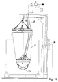
- FIGS. 1 a and b show the respective emptying device in FIG the side view, once with almost complete filling of the container. 6 with bulk material 13 and once with almost completely emptied container 6.
- the container 6 is one in an octabin 7, so with solid container walls, taken on a pallet under the superstructure of the Emptying device is.
- the emptying device in each case comprises a holding frame 1, the horizontal annularly centrally above the bag-shaped container. 6 is arranged and the upper edge of the container 6 by means of a holding element 21 in the form of a circumferential around the support frame 1 clamping belt holds.
- the support frame 1 is pulled by means of a cable 3 'up, over Deflection rollers 9 'along the transverse strut 19 and the vertical strut 20 along is and is connected to a container cylinder 24, with the help of the Holding frame 1 pulled up and thus - as shown in Fig. 1 b - the Side walls can be straightened.
- the holding frame 1 Since the holding frame 1 has a smaller diameter than the container 6 in filled state, the side walls of the bag-shaped container especially in the area above the bulk material 13 pulled inwards until - Towards the end of the emptying process - they rest on the suction head 4 outside.
- the suction head 4, from which the suction hose 16 leads upwards, is also by means of a cable 3, which is guided over analog deflection rollers 8, 9, too another lifting cylinder 14 out, which is the raising and lowering of the Suction head is used.
- Both cylinders 14, 24 are vertical to the vertical strut 20, in particular to their rear side facing away from the octabine 7, attached, and are about a Controlled 17, either on the vertical strut 20 or on a separate hanging cable is attached.
- controller 17 is e.g. set whether and how often the suction head 4 off the bulk material 13 is pulled out and lowered again on this, and / or how deep the suction head 4 after placement on the surface of the bulk material 13 may sink before lifting and pulling out of the Bulk material takes place, which is carried out several times in succession.
- the cable 3 at the end of the piston rod of Lifting cylinder 14 not directly attached, but at the end only one another role 26 out, and ends at a fixed point.
- the height of the vertical strut 20 or 20 is sufficient for attachment an approximately half as long cylinder 14 thereon, so if the other half of Height of the vertical strut 20 or 20 "available as a movement path of the roller stands.
- the suction head 4 in addition to Compressed air nozzles 33 is equipped, the compressed air jets 32 from the suction head 4 from directed radially outward against the bulk material 13, preferably obliquely directed downwards, against the walls of the suction hole 18, which is formed by the suction of bulk material 13 from above in the middle of the container.
- the goal here is, on the one hand, always plenty of enough, so not glued or otherwise solidified bulk material 13 in the area to bring the suction opening 4a of the suction head 4, and on the other hand, the emerging suction hole 18 as large as possible to make the remaining forming walls as far apart as possible on bulk material 13, what facilitates their collapse, what by pulling up the baggy 6 container and with the walls constantly pushing in or out time intervals is promoted.
- All compressed air nozzles 33 are connected via a central supply line 35, the is preferably guided along the suction hose 16 to the suction head 4, with Compressed air supplied.
- the suction nozzles 33 In the upper level are the suction nozzles 33 by means of brackets 34, always carry two or more nozzles 33, along the upper peripheral edge of the Suction head 4 attached, for example by the headband 34 on the top the suction head 4 are screwed, so that the nozzles 33 just above the Upper edge are positioned.
- nozzles 33 are in a second, deeper level along the Conical surface of the suction head arranged. It may be used in other, e.g. third even deeper level, nozzles 33 are arranged, which then still are positioned closer to the suction opening 4a.
- the nozzles 33 are each directed radially outward and obliquely downward, and preferably the more downward, the deeper and closer to the Suction opening 4a they are arranged on the suction head 4.
- the suction head 4 works like Described in the bulk material 13 down, wherein the suction hole 18th collapse surrounding walls of bulk material 13 or brought to collapse and slipping down until the quasi-completely empty state 1 b is achieved by the bag-like container 6 on the outer circumference the suction head 4 is applied and at most in the remaining distance between the underside of the suction head 4 and the container 6 extending there still Remains of bulk 13 are present in very small amount.
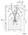
- FIG. 2 shows an emptying device, wherein the support frame 43 not only from a vertical strut 20 and an abstreben from above free cantilever cross member 19 is made, but portal-shaped with two distinguished Vertical struts 20 and one connecting them, mounted on both sides Cross strut 19 'exists.
- the suction head 4 ' is also designed differently, and consists essentially of a suction lance 39, so a piece of pipe whose open lower end the Suction port 4a represents, and at the upper end of the flexible suction hose 16 is connected.
- compressed air nozzles 33 which point obliquely outwards at the bottom Surface, in this case the downward conical surface of the weight body 25 of the suction head 4 '- this time only in a single vertical plane circumferential - arranged.
- the nozzles 33 may be via lines or Holes in the interior of the weight body 25 with that of the supply line 35 supplied compressed air are supplied.
- FIG. 2 Another special feature is in Figure 2 due to a small upper opening of the container 6 'an air supply line 26 from outside the container 6' to Suction head 4 'out, which provides supply air near the suction opening 4a, to avoid that the suction process is interrupted because of a defect on inflowing air.
- a weight is still a special one Fixed outer contour forming body, but in two superimposed arranged levels are on the suction lance 39 in each plane above the Scope distributed several suction nozzles 33 arranged on the suction lance 39, and although from bottom to top with increasing radial, horizontal distance from 3 vertical suction lance 39th
- the nozzles 33 are from the lower end, that is Suction opening 4a, offset upwards circulating directly on the outer circumference of the Suction lance 39 arranged.
- the nozzles 33 are spaced radially outward, in FIG vertical direction approximately at the height of the transition between suction lance 39 and flexible suction hose 16, arranged, for example, again by means of in Figure 1 mentioned retaining bracket 34 which on a suction lance 39 surrounding Ring or circular plate can be attached and therefore - as in the solution can be retrofitted to a conventional suction head 4, 4 'according to Figure 1 or 2.
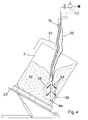
- FIG. 4 clearly shows that such a cone-shaped Suction hole 18 is not formed when, as shown in Figure 4 in several levels at e.g. the suction lance 39 superposed nozzles 33 each have the same have lateral radial distance to the central axis and thus the suction lance 39, by directly on the outer circumference of the suction lance 39 as in FIG are arranged.
- FIG. 4 differs from that of FIG Figures 1 to 3, characterized in that in Figure 4 of a suction lance 39 existing Suction head, as shown in Figures 1 to 3 with a flexible suction hose in Connection stands and its compressed air nozzles 33 by means of a compressed air supply line 35 are supplied, even at a liftable Hoist is attached, still the container is attached to a hoist, which in the present case of an octabin 7 with fixed peripheral walls consists.
- the octabin 7 stands on a base plate 23 ', which by means of e.g. Hydraulic cylinder can be tilted obliquely, so that one of the lower edges of the Octabins 7 represents its lowest point at the end of the Fill state collect the remains of bulk material 13. The inclination is only after partial emptying of octabin 7 performed.
- suction lance 39 in the absence of a hoist At least somewhat in position to fix, is at the suction lance 39 and / or the suction hose 16 above a suspension device 41, e.g. in the form of a Ein vonbügels, arranged by means of which the suction lance the top of the octabin 7 can be hung.
- a suspension device 41 e.g. in the form of a Ein vonbügels
- Fig. 5 shows a solution with suction pipe 16, preferably to the after downwardly curved portion 16a a telescoping portion 16b to Enlargement of the effective radius connects.
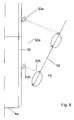
- Figure 6 also shows in detail - set out the example of compressed air nozzles 33, which are located directly on the outer circumference of a suction lance 39, but not limited thereto - on the one hand, the mode of action of the different far radially outwardly acting compressed air jets 32, the upper Compressed air jets 32a of the upper nozzles 33a radially outwardly act as the lower beams 32b and thereby the mentioned conical shape of the suction hole 18 is achieved despite non-conical arrangement of the nozzles 33 a, b.
- Compressed air jet 32a is not always directed in the same direction, but runs annular around a central axis and thus processed a much larger Circular surface or annular surface on the surface of the suction hole 18, as it the cross section of the compressed air jet 32a, b corresponds directly. additionally and / or instead, the compressed air jet 32 may also pulsate to Reduced compressed air consumption to achieve an approximately equally good effect.
- Fig. 7 shows a construction in which, e.g. annular retaining element 21 ' a plurality of intake openings 4a, b distributed over a larger area annularly and possibly also at different altitudes, e.g. along a virtual cone, are arranged as a suction head 4 ":
- the free lower ends of the suction openings 4a, b ... are, or on a reverse as in Figure 1 frusto-conical Suction head 4 can distributed over the circumference a plurality of suction openings 4a, b ... - possibly also in several altitudes - be present.
- compressed air nozzles 33 are again arranged on the holding element 21 '. which act on the environment of the suction openings 4a, b ... with compressed air to solve the local bulk material 13 and to the suction openings 4a, b ... flow allow.
- the suction openings 4a, b ... preferably with a - not shown - central suction hose connected, either the sum the cross sections of the suction openings 4a, b ... is smaller than the cross section of this common suction hose 16 or the individual suction openings 4a, b ... be alternately from the negative pressure of the central suction hose applied.
- the holding element 21 'can simultaneously for securing the upper edge of the Serve container 6, which are using the rope 3 'tightened and pulled up can, of course, in alternation with the lowering of the intake ports 4a, b ... on the surface of the bulk material 13.
- FIG. 8 shows, in a detailed representation to FIGS. 1 a, b, a possibility for the Deflection pulley 8 for the rope 3 of the suction head in the horizontal plane circulate circular, without thereby the suction head 4 itself its own axis turns. This makes it possible, the suction head 4 within the Container 6 a larger workspace than horizontally unchanged Work off position.
- a rotary drive of the rotary plate 42 in a very simple way and Way be realized, for example, that with the rotary plate 42 a Rope winding roller 44 is rotatably connected, on which a rope 3 "is wound, which at any suitable point with the rope 3 for lifting and lowering the suction head is connected.
- the rope 3 "wound on the Winder 44 up or down, including the winding roller 44 in the winding of a not shown spring, for example a spirally wound flat spiral spring, is biased, so that with the compressed air nozzles acting radially to the side equipped suction head spirals down into the container and the bulk material 13 lowered into it, creating only very thin peripheral walls of the Bulk material 13 remain, which easily collapse or brought to collapse can be.
- a not shown spring for example a spirally wound flat spiral spring
Landscapes
- Engineering & Computer Science (AREA)
- Mechanical Engineering (AREA)
- Basic Packing Technique (AREA)
- Control And Other Processes For Unpacking Of Materials (AREA)
- Processing And Handling Of Plastics And Other Materials For Molding In General (AREA)
- Supplying Of Containers To The Packaging Station (AREA)
Applications Claiming Priority (2)
| Application Number | Priority Date | Filing Date | Title |
|---|---|---|---|
| DE102004015014 | 2004-03-26 | ||
| DE102004015014A DE102004015014A1 (de) | 2004-03-26 | 2004-03-26 | Verfahren und Vorrichtung zum Entleeren von Schüttgut |
Publications (3)
| Publication Number | Publication Date |
|---|---|
| EP1580133A2 true EP1580133A2 (fr) | 2005-09-28 |
| EP1580133A3 EP1580133A3 (fr) | 2006-09-20 |
| EP1580133B1 EP1580133B1 (fr) | 2010-04-07 |
Family
ID=34854079
Family Applications (1)
| Application Number | Title | Priority Date | Filing Date |
|---|---|---|---|
| EP04017777A Expired - Lifetime EP1580133B1 (fr) | 2004-03-26 | 2004-07-27 | Procédé et dispositif de déchargement de produit en vrac |
Country Status (3)
| Country | Link |
|---|---|
| EP (1) | EP1580133B1 (fr) |
| AT (1) | ATE463430T1 (fr) |
| DE (2) | DE102004015014A1 (fr) |
Cited By (10)
| Publication number | Priority date | Publication date | Assignee | Title |
|---|---|---|---|---|
| WO2007081475A1 (fr) | 2006-01-06 | 2007-07-19 | Valspar Sourcing, Inc. | Procédé et appareil pour système d'acheminement de poudre |
| EP2045199A1 (fr) | 2007-10-02 | 2009-04-08 | Klaus Wilhelm | Appareil à air comprimé pour alimenter en poudre ou en matériaux granulaires |
| US8104997B2 (en) | 2008-04-14 | 2012-01-31 | Maguire Stephen B | Bulk resin unloading apparatus and method |
| EP2308784A3 (fr) * | 2009-10-07 | 2013-05-29 | Helmut Schellinger | Dispositif d'extraction pour l'agencement dans un stockage, stockage doté d'un dispositif d'extraction et procédé d'extraction et de remplissage de produits en vrac |
| US8747028B2 (en) | 2008-04-14 | 2014-06-10 | Stephen B. Maguire | Container emptying apparatus and method |
| WO2015193919A3 (fr) * | 2014-06-20 | 2016-02-11 | Shah Amal Bhupendra | Appareil de tamisage vibratoire et système pour tamisage en temps réel |
| CN109095019A (zh) * | 2018-07-03 | 2018-12-28 | 上海城投污水处理有限公司 | 送料密封系统及其采用的对接密封方法 |
| CN111071504A (zh) * | 2020-01-03 | 2020-04-28 | 广东亨通光电科技有限公司 | 一种吸料装置及加注设备 |
| CN115849014A (zh) * | 2022-12-13 | 2023-03-28 | 浙江软控智能科技有限公司 | 一种吨包吸料装置 |
| CN116040323A (zh) * | 2023-02-28 | 2023-05-02 | 包头市明芯科技有限公司 | 一种粉料输送装置 |
Families Citing this family (2)
| Publication number | Priority date | Publication date | Assignee | Title |
|---|---|---|---|---|
| DE202006015899U1 (de) | 2006-10-13 | 2006-12-21 | Westdeutscher Drahtseil-Verkauf Dolezych Gmbh & Co. | Sicherungsmittel für Schüttgutbehälter |
| WO2012084734A1 (fr) | 2010-12-22 | 2012-06-28 | Basf Se | Dispositif d'aspiration et procédé pour extraire de la matière en vrac d'un contenant |
Family Cites Families (9)
| Publication number | Priority date | Publication date | Assignee | Title |
|---|---|---|---|---|
| DE3004945A1 (de) * | 1980-02-09 | 1981-08-20 | Degussa Ag, 6000 Frankfurt | Vorrichtung zum entleeren von mit pulvern gefuellten behaeltern |
| DE8805947U1 (de) * | 1988-05-04 | 1988-07-28 | Krämer, Erich, 96247 Michelau | Vorrichtung zum Zuführen eines pulverförmigen Materials zu einer Versorgungseinrichtung |
| DE3920635A1 (de) * | 1989-06-23 | 1991-01-03 | Wagner Int | Einrichtung zum fluidisieren und abfoerdern von pulver |
| DE4021674A1 (de) * | 1990-07-07 | 1992-01-16 | Gema Ransburg Ag | Vorrichtung zum pneumatischen foerdern von pulver aus einem behaelter |
| DE19506538C2 (de) * | 1995-02-24 | 1999-09-16 | Helmut Haas | Pulver-Entnahmevorrichtung |
| DK0761566T3 (da) * | 1995-09-12 | 2001-09-10 | Degussa | Fremgangsmåde og apparat til fjernelse af fint materiale fra en beholder |
| JPH10511070A (ja) * | 1995-10-02 | 1998-10-27 | ヴィルヘルム,クラウス | 粉体物質用容器の吸引装置 |
| DE29803070U1 (de) * | 1998-02-23 | 1998-11-05 | Sandi, Roland, Meggen | Saugkopf für Sackentleerungsvorrichtung |
| DE29823358U1 (de) * | 1998-11-13 | 1999-05-06 | Wilhelm, Nikolaus, 83022 Rosenheim | Entleervorrichtung für rieselfähiges Schüttgut |
-
2004
- 2004-03-26 DE DE102004015014A patent/DE102004015014A1/de not_active Withdrawn
- 2004-07-27 DE DE502004010993T patent/DE502004010993D1/de not_active Expired - Lifetime
- 2004-07-27 EP EP04017777A patent/EP1580133B1/fr not_active Expired - Lifetime
- 2004-07-27 AT AT04017777T patent/ATE463430T1/de not_active IP Right Cessation
Cited By (14)
| Publication number | Priority date | Publication date | Assignee | Title |
|---|---|---|---|---|
| CN101356013B (zh) * | 2006-01-06 | 2012-10-24 | 威士伯采购公司 | 用于传输粉末油漆的系统及方法 |
| US7963728B2 (en) | 2006-01-06 | 2011-06-21 | Valspar Sourcing, Inc. | Method and apparatus for powder delivery system |
| WO2007081475A1 (fr) | 2006-01-06 | 2007-07-19 | Valspar Sourcing, Inc. | Procédé et appareil pour système d'acheminement de poudre |
| EP2045199A1 (fr) | 2007-10-02 | 2009-04-08 | Klaus Wilhelm | Appareil à air comprimé pour alimenter en poudre ou en matériaux granulaires |
| US8747028B2 (en) | 2008-04-14 | 2014-06-10 | Stephen B. Maguire | Container emptying apparatus and method |
| US8104997B2 (en) | 2008-04-14 | 2012-01-31 | Maguire Stephen B | Bulk resin unloading apparatus and method |
| EP2308784A3 (fr) * | 2009-10-07 | 2013-05-29 | Helmut Schellinger | Dispositif d'extraction pour l'agencement dans un stockage, stockage doté d'un dispositif d'extraction et procédé d'extraction et de remplissage de produits en vrac |
| WO2015193919A3 (fr) * | 2014-06-20 | 2016-02-11 | Shah Amal Bhupendra | Appareil de tamisage vibratoire et système pour tamisage en temps réel |
| US10322426B2 (en) | 2014-06-20 | 2019-06-18 | Amal Bhupendra SHAH | Vibrating sieving apparatus and a system for real time sieving |
| CN109095019A (zh) * | 2018-07-03 | 2018-12-28 | 上海城投污水处理有限公司 | 送料密封系统及其采用的对接密封方法 |
| CN109095019B (zh) * | 2018-07-03 | 2023-10-20 | 上海城投污水处理有限公司 | 送料密封系统及其采用的对接密封方法 |
| CN111071504A (zh) * | 2020-01-03 | 2020-04-28 | 广东亨通光电科技有限公司 | 一种吸料装置及加注设备 |
| CN115849014A (zh) * | 2022-12-13 | 2023-03-28 | 浙江软控智能科技有限公司 | 一种吨包吸料装置 |
| CN116040323A (zh) * | 2023-02-28 | 2023-05-02 | 包头市明芯科技有限公司 | 一种粉料输送装置 |
Also Published As
| Publication number | Publication date |
|---|---|
| ATE463430T1 (de) | 2010-04-15 |
| DE102004015014A1 (de) | 2005-10-13 |
| EP1580133A3 (fr) | 2006-09-20 |
| DE502004010993D1 (de) | 2010-05-20 |
| EP1580133B1 (fr) | 2010-04-07 |
Similar Documents
| Publication | Publication Date | Title |
|---|---|---|
| EP2380813B1 (fr) | Procédé et dispositif pour décharger des produits en vrac | |
| DE19628429C2 (de) | Entleervorrichtung für rieselfähiges Schüttgut | |
| EP0337132B1 (fr) | Dispositif pour amener des matières pulvérulentes à un dispositif de distribution | |
| EP1580133B1 (fr) | Procédé et dispositif de déchargement de produit en vrac | |
| DE2235747A1 (de) | Verfahren und vorrichtung zum verladen von schuettgut | |
| EP1334931A1 (fr) | Arrangement et procédé pour prelever des quantities partielles d'une composition de revêtement d'un sack de poudre | |
| DE4218331C2 (de) | Vorrichtung zur Entleerung von Schüttgutbehältern | |
| DE4339492A1 (de) | Pulverlackieranlage mit einer Kabine mit variablem Querschnitt | |
| EP0878241A2 (fr) | Installation de captation de la poudre excédentaire lors du revêtement par poudrage de pièces | |
| EP1199266B1 (fr) | Dispositif et procédé pour l'évacuation de produit en vrac | |
| EP0943560A1 (fr) | Station automatisée pour vider des sacs | |
| DE19506538C2 (de) | Pulver-Entnahmevorrichtung | |
| EP3552714B1 (fr) | Transporteur de poudre destiné à transporter le poudre de revêtement, méthode de fabriquation de transportateur et centre d'alimentation en poudre pourvu de transporteur de poudre destiné à alimenter un centre d'alimentation en poudre | |
| DE2024296A1 (de) | Beschickungseinrichtung für Vibrationsmühlen | |
| DE102009020600A1 (de) | Vorrichtung und Verfahren zum Aufnehmen und Entleeren von Transportbehältern | |
| DE3151638C2 (de) | Pneumatische Absaugvorrichtung zum Entleeren von Schroten o.dgl. aus Schiffen | |
| EP1090856A1 (fr) | Système et procédé pour le déchargement d'un conteneur, notamment d'un conteneur de transport en forme de caisson | |
| DE2541583C3 (de) | Vorrichtung zum Einebnen und Ausräumen von Schüttgut in bzw. aus Gutbehandlungsräumen, insbesondere für Mälzereien | |
| DE19948938A1 (de) | Vorrichtung zum Einfüllen von Beton aus einem Betonkübel in eine Schalung | |
| DE3913855A1 (de) | Vorrichtung zur uebergabe von mit geknoteten aufhaengeschlaufen versehenen bearbeitungsstuecken auf eine transporteinrichtung | |
| DE3928115C2 (fr) | ||
| DE2701010C3 (de) | Verfahren zum Dosieren von körnigem Gut für Strahlmittelbehandlungsanlagen | |
| DE2313779A1 (de) | Beladevorrichtung oder beladekopf fuer schuettgut | |
| DE29612187U1 (de) | Entleervorrichtung für rieselfähiges Schüttgut | |
| AT5475U1 (de) | Vorrichtung zum einfüllen von beton aus einem betonkübel in eine schalung |
Legal Events
| Date | Code | Title | Description |
|---|---|---|---|
| PUAI | Public reference made under article 153(3) epc to a published international application that has entered the european phase |
Free format text: ORIGINAL CODE: 0009012 |
|
| AK | Designated contracting states |
Kind code of ref document: A2 Designated state(s): AT BE BG CH CY CZ DE DK EE ES FI FR GB GR HU IE IT LI LU MC NL PL PT RO SE SI SK TR |
|
| AX | Request for extension of the european patent |
Extension state: AL HR LT LV MK |
|
| PUAL | Search report despatched |
Free format text: ORIGINAL CODE: 0009013 |
|
| AK | Designated contracting states |
Kind code of ref document: A3 Designated state(s): AT BE BG CH CY CZ DE DK EE ES FI FR GB GR HU IE IT LI LU MC NL PL PT RO SE SI SK TR |
|
| AX | Request for extension of the european patent |
Extension state: AL HR LT LV MK |
|
| RIC1 | Information provided on ipc code assigned before grant |
Ipc: B65G 53/42 20060101ALI20060814BHEP Ipc: B65B 69/00 20060101AFI20050719BHEP |
|
| 17P | Request for examination filed |
Effective date: 20061023 |
|
| 17Q | First examination report despatched |
Effective date: 20070226 |
|
| AKX | Designation fees paid |
Designated state(s): AT BE BG CH CY CZ DE DK EE ES FI FR GB GR HU IE IT LI LU MC NL PL PT RO SE SI SK TR |
|
| GRAP | Despatch of communication of intention to grant a patent |
Free format text: ORIGINAL CODE: EPIDOSNIGR1 |
|
| GRAS | Grant fee paid |
Free format text: ORIGINAL CODE: EPIDOSNIGR3 |
|
| GRAA | (expected) grant |
Free format text: ORIGINAL CODE: 0009210 |
|
| AK | Designated contracting states |
Kind code of ref document: B1 Designated state(s): AT BE BG CH CY CZ DE DK EE ES FI FR GB GR HU IE IT LI LU MC NL PL PT RO SE SI SK TR |
|
| REG | Reference to a national code |
Ref country code: GB Ref legal event code: FG4D Free format text: NOT ENGLISH |
|
| REG | Reference to a national code |
Ref country code: CH Ref legal event code: EP |
|
| REG | Reference to a national code |
Ref country code: IE Ref legal event code: FG4D Free format text: LANGUAGE OF EP DOCUMENT: GERMAN |
|
| REF | Corresponds to: |
Ref document number: 502004010993 Country of ref document: DE Date of ref document: 20100520 Kind code of ref document: P |
|
| REG | Reference to a national code |
Ref country code: NL Ref legal event code: VDEP Effective date: 20100407 |
|
| PG25 | Lapsed in a contracting state [announced via postgrant information from national office to epo] |
Ref country code: SI Free format text: LAPSE BECAUSE OF FAILURE TO SUBMIT A TRANSLATION OF THE DESCRIPTION OR TO PAY THE FEE WITHIN THE PRESCRIBED TIME-LIMIT Effective date: 20100407 |
|
| REG | Reference to a national code |
Ref country code: IE Ref legal event code: FD4D |
|
| PG25 | Lapsed in a contracting state [announced via postgrant information from national office to epo] |
Ref country code: SE Free format text: LAPSE BECAUSE OF FAILURE TO SUBMIT A TRANSLATION OF THE DESCRIPTION OR TO PAY THE FEE WITHIN THE PRESCRIBED TIME-LIMIT Effective date: 20100407 Ref country code: NL Free format text: LAPSE BECAUSE OF FAILURE TO SUBMIT A TRANSLATION OF THE DESCRIPTION OR TO PAY THE FEE WITHIN THE PRESCRIBED TIME-LIMIT Effective date: 20100407 Ref country code: ES Free format text: LAPSE BECAUSE OF FAILURE TO SUBMIT A TRANSLATION OF THE DESCRIPTION OR TO PAY THE FEE WITHIN THE PRESCRIBED TIME-LIMIT Effective date: 20100718 |
|
| PG25 | Lapsed in a contracting state [announced via postgrant information from national office to epo] |
Ref country code: FI Free format text: LAPSE BECAUSE OF FAILURE TO SUBMIT A TRANSLATION OF THE DESCRIPTION OR TO PAY THE FEE WITHIN THE PRESCRIBED TIME-LIMIT Effective date: 20100407 |
|
| PGFP | Annual fee paid to national office [announced via postgrant information from national office to epo] |
Ref country code: AT Payment date: 20100721 Year of fee payment: 7 |
|
| PG25 | Lapsed in a contracting state [announced via postgrant information from national office to epo] |
Ref country code: GR Free format text: LAPSE BECAUSE OF FAILURE TO SUBMIT A TRANSLATION OF THE DESCRIPTION OR TO PAY THE FEE WITHIN THE PRESCRIBED TIME-LIMIT Effective date: 20100708 Ref country code: CY Free format text: LAPSE BECAUSE OF FAILURE TO SUBMIT A TRANSLATION OF THE DESCRIPTION OR TO PAY THE FEE WITHIN THE PRESCRIBED TIME-LIMIT Effective date: 20100421 Ref country code: PL Free format text: LAPSE BECAUSE OF FAILURE TO SUBMIT A TRANSLATION OF THE DESCRIPTION OR TO PAY THE FEE WITHIN THE PRESCRIBED TIME-LIMIT Effective date: 20100407 |
|
| BERE | Be: lapsed |
Owner name: HELIOS GERATEBAU FUR KUNSTSTOFFTECHNIK G.M.B.H. Effective date: 20100731 |
|
| PG25 | Lapsed in a contracting state [announced via postgrant information from national office to epo] |
Ref country code: DK Free format text: LAPSE BECAUSE OF FAILURE TO SUBMIT A TRANSLATION OF THE DESCRIPTION OR TO PAY THE FEE WITHIN THE PRESCRIBED TIME-LIMIT Effective date: 20100407 Ref country code: EE Free format text: LAPSE BECAUSE OF FAILURE TO SUBMIT A TRANSLATION OF THE DESCRIPTION OR TO PAY THE FEE WITHIN THE PRESCRIBED TIME-LIMIT Effective date: 20100407 Ref country code: PT Free format text: LAPSE BECAUSE OF FAILURE TO SUBMIT A TRANSLATION OF THE DESCRIPTION OR TO PAY THE FEE WITHIN THE PRESCRIBED TIME-LIMIT Effective date: 20100809 Ref country code: IE Free format text: LAPSE BECAUSE OF FAILURE TO SUBMIT A TRANSLATION OF THE DESCRIPTION OR TO PAY THE FEE WITHIN THE PRESCRIBED TIME-LIMIT Effective date: 20100407 |
|
| PLBE | No opposition filed within time limit |
Free format text: ORIGINAL CODE: 0009261 |
|
| STAA | Information on the status of an ep patent application or granted ep patent |
Free format text: STATUS: NO OPPOSITION FILED WITHIN TIME LIMIT |
|
| PG25 | Lapsed in a contracting state [announced via postgrant information from national office to epo] |
Ref country code: CZ Free format text: LAPSE BECAUSE OF FAILURE TO SUBMIT A TRANSLATION OF THE DESCRIPTION OR TO PAY THE FEE WITHIN THE PRESCRIBED TIME-LIMIT Effective date: 20100407 Ref country code: SK Free format text: LAPSE BECAUSE OF FAILURE TO SUBMIT A TRANSLATION OF THE DESCRIPTION OR TO PAY THE FEE WITHIN THE PRESCRIBED TIME-LIMIT Effective date: 20100407 Ref country code: RO Free format text: LAPSE BECAUSE OF FAILURE TO SUBMIT A TRANSLATION OF THE DESCRIPTION OR TO PAY THE FEE WITHIN THE PRESCRIBED TIME-LIMIT Effective date: 20100407 Ref country code: MC Free format text: LAPSE BECAUSE OF NON-PAYMENT OF DUE FEES Effective date: 20100731 |
|
| 26N | No opposition filed |
Effective date: 20110110 |
|
| PG25 | Lapsed in a contracting state [announced via postgrant information from national office to epo] |
Ref country code: IT Free format text: LAPSE BECAUSE OF FAILURE TO SUBMIT A TRANSLATION OF THE DESCRIPTION OR TO PAY THE FEE WITHIN THE PRESCRIBED TIME-LIMIT Effective date: 20100407 |
|
| PG25 | Lapsed in a contracting state [announced via postgrant information from national office to epo] |
Ref country code: BE Free format text: LAPSE BECAUSE OF NON-PAYMENT OF DUE FEES Effective date: 20100731 |
|
| REG | Reference to a national code |
Ref country code: AT Ref legal event code: MM01 Ref document number: 463430 Country of ref document: AT Kind code of ref document: T Effective date: 20110727 |
|
| PG25 | Lapsed in a contracting state [announced via postgrant information from national office to epo] |
Ref country code: LU Free format text: LAPSE BECAUSE OF NON-PAYMENT OF DUE FEES Effective date: 20100727 Ref country code: BG Free format text: LAPSE BECAUSE OF FAILURE TO SUBMIT A TRANSLATION OF THE DESCRIPTION OR TO PAY THE FEE WITHIN THE PRESCRIBED TIME-LIMIT Effective date: 20100407 Ref country code: HU Free format text: LAPSE BECAUSE OF FAILURE TO SUBMIT A TRANSLATION OF THE DESCRIPTION OR TO PAY THE FEE WITHIN THE PRESCRIBED TIME-LIMIT Effective date: 20101008 |
|
| PG25 | Lapsed in a contracting state [announced via postgrant information from national office to epo] |
Ref country code: TR Free format text: LAPSE BECAUSE OF FAILURE TO SUBMIT A TRANSLATION OF THE DESCRIPTION OR TO PAY THE FEE WITHIN THE PRESCRIBED TIME-LIMIT Effective date: 20100407 |
|
| PG25 | Lapsed in a contracting state [announced via postgrant information from national office to epo] |
Ref country code: AT Free format text: LAPSE BECAUSE OF NON-PAYMENT OF DUE FEES Effective date: 20110727 |
|
| PG25 | Lapsed in a contracting state [announced via postgrant information from national office to epo] |
Ref country code: BG Free format text: LAPSE BECAUSE OF FAILURE TO SUBMIT A TRANSLATION OF THE DESCRIPTION OR TO PAY THE FEE WITHIN THE PRESCRIBED TIME-LIMIT Effective date: 20100707 |
|
| REG | Reference to a national code |
Ref country code: DE Ref legal event code: R082 Ref document number: 502004010993 Country of ref document: DE Representative=s name: PATENTANWAELTE WEICKMANN & WEICKMANN, DE Ref country code: DE Ref legal event code: R082 Ref document number: 502004010993 Country of ref document: DE Representative=s name: WEICKMANN & WEICKMANN PATENTANWAELTE - RECHTSA, DE Ref country code: DE Ref legal event code: R082 Ref document number: 502004010993 Country of ref document: DE Representative=s name: WEICKMANN & WEICKMANN PATENT- UND RECHTSANWAEL, DE |
|
| REG | Reference to a national code |
Ref country code: FR Ref legal event code: PLFP Year of fee payment: 13 |
|
| REG | Reference to a national code |
Ref country code: FR Ref legal event code: PLFP Year of fee payment: 14 |
|
| REG | Reference to a national code |
Ref country code: FR Ref legal event code: PLFP Year of fee payment: 15 |
|
| PGFP | Annual fee paid to national office [announced via postgrant information from national office to epo] |
Ref country code: IT Payment date: 20180921 Year of fee payment: 16 |
|
| PGFP | Annual fee paid to national office [announced via postgrant information from national office to epo] |
Ref country code: GB Payment date: 20180725 Year of fee payment: 15 |
|
| GBPC | Gb: european patent ceased through non-payment of renewal fee |
Effective date: 20190727 |
|
| PG25 | Lapsed in a contracting state [announced via postgrant information from national office to epo] |
Ref country code: GB Free format text: LAPSE BECAUSE OF NON-PAYMENT OF DUE FEES Effective date: 20190727 |
|
| PG25 | Lapsed in a contracting state [announced via postgrant information from national office to epo] |
Ref country code: FR Free format text: LAPSE BECAUSE OF NON-PAYMENT OF DUE FEES Effective date: 20190731 |
|
| PGFP | Annual fee paid to national office [announced via postgrant information from national office to epo] |
Ref country code: DE Payment date: 20200727 Year of fee payment: 17 |
|
| PGFP | Annual fee paid to national office [announced via postgrant information from national office to epo] |
Ref country code: CH Payment date: 20210721 Year of fee payment: 18 |
|
| REG | Reference to a national code |
Ref country code: DE Ref legal event code: R119 Ref document number: 502004010993 Country of ref document: DE |
|
| PG25 | Lapsed in a contracting state [announced via postgrant information from national office to epo] |
Ref country code: DE Free format text: LAPSE BECAUSE OF NON-PAYMENT OF DUE FEES Effective date: 20220201 |
|
| REG | Reference to a national code |
Ref country code: CH Ref legal event code: PL |
|
| PG25 | Lapsed in a contracting state [announced via postgrant information from national office to epo] |
Ref country code: LI Free format text: LAPSE BECAUSE OF NON-PAYMENT OF DUE FEES Effective date: 20220731 Ref country code: CH Free format text: LAPSE BECAUSE OF NON-PAYMENT OF DUE FEES Effective date: 20220731 |
|
| P01 | Opt-out of the competence of the unified patent court (upc) registered |
Effective date: 20230526 |