EP1580165A1 - Verfahren zur Herstellung von hydrophilen Kohlenstoffnanoröhren - Google Patents
Verfahren zur Herstellung von hydrophilen Kohlenstoffnanoröhren Download PDFInfo
- Publication number
- EP1580165A1 EP1580165A1 EP05251799A EP05251799A EP1580165A1 EP 1580165 A1 EP1580165 A1 EP 1580165A1 EP 05251799 A EP05251799 A EP 05251799A EP 05251799 A EP05251799 A EP 05251799A EP 1580165 A1 EP1580165 A1 EP 1580165A1
- Authority
- EP
- European Patent Office
- Prior art keywords
- carbon nanotubes
- ultraviolet ray
- irradiation
- hydrophilic carbon
- manufacturing hydrophilic
- Prior art date
- Legal status (The legal status is an assumption and is not a legal conclusion. Google has not performed a legal analysis and makes no representation as to the accuracy of the status listed.)
- Granted
Links
Images

Classifications
-
- C—CHEMISTRY; METALLURGY
- C01—INORGANIC CHEMISTRY
- C01B—NON-METALLIC ELEMENTS; COMPOUNDS THEREOF; METALLOIDS OR COMPOUNDS THEREOF NOT COVERED BY SUBCLASS C01C
- C01B32/00—Carbon; Compounds thereof
- C01B32/15—Nano-sized carbon materials
- C01B32/158—Carbon nanotubes
- C01B32/16—Preparation
- C01B32/162—Preparation characterised by catalysts
-
- B—PERFORMING OPERATIONS; TRANSPORTING
- B01—PHYSICAL OR CHEMICAL PROCESSES OR APPARATUS IN GENERAL
- B01J—CHEMICAL OR PHYSICAL PROCESSES, e.g. CATALYSIS OR COLLOID CHEMISTRY; THEIR RELEVANT APPARATUS
- B01J19/00—Chemical, physical or physico-chemical processes in general; Their relevant apparatus
- B01J19/08—Processes employing the direct application of electric or wave energy, or particle radiation; Apparatus therefor
- B01J19/12—Processes employing the direct application of electric or wave energy, or particle radiation; Apparatus therefor employing electromagnetic waves
- B01J19/122—Incoherent waves
- B01J19/123—Ultraviolet light
-
- B—PERFORMING OPERATIONS; TRANSPORTING
- B01—PHYSICAL OR CHEMICAL PROCESSES OR APPARATUS IN GENERAL
- B01J—CHEMICAL OR PHYSICAL PROCESSES, e.g. CATALYSIS OR COLLOID CHEMISTRY; THEIR RELEVANT APPARATUS
- B01J23/00—Catalysts comprising metals or metal oxides or hydroxides, not provided for in group B01J21/00
- B01J23/70—Catalysts comprising metals or metal oxides or hydroxides, not provided for in group B01J21/00 of the iron group metals or copper
- B01J23/74—Iron group metals
- B01J23/745—Iron
-
- B—PERFORMING OPERATIONS; TRANSPORTING
- B82—NANOTECHNOLOGY
- B82Y—SPECIFIC USES OR APPLICATIONS OF NANOSTRUCTURES; MEASUREMENT OR ANALYSIS OF NANOSTRUCTURES; MANUFACTURE OR TREATMENT OF NANOSTRUCTURES
- B82Y30/00—Nanotechnology for materials or surface science, e.g. nanocomposites
-
- B—PERFORMING OPERATIONS; TRANSPORTING
- B82—NANOTECHNOLOGY
- B82Y—SPECIFIC USES OR APPLICATIONS OF NANOSTRUCTURES; MEASUREMENT OR ANALYSIS OF NANOSTRUCTURES; MANUFACTURE OR TREATMENT OF NANOSTRUCTURES
- B82Y40/00—Manufacture or treatment of nanostructures
-
- C—CHEMISTRY; METALLURGY
- C01—INORGANIC CHEMISTRY
- C01B—NON-METALLIC ELEMENTS; COMPOUNDS THEREOF; METALLOIDS OR COMPOUNDS THEREOF NOT COVERED BY SUBCLASS C01C
- C01B32/00—Carbon; Compounds thereof
- C01B32/15—Nano-sized carbon materials
- C01B32/158—Carbon nanotubes
- C01B32/168—After-treatment
- C01B32/174—Derivatisation; Solubilisation; Dispersion in solvents
-
- C—CHEMISTRY; METALLURGY
- C01—INORGANIC CHEMISTRY
- C01B—NON-METALLIC ELEMENTS; COMPOUNDS THEREOF; METALLOIDS OR COMPOUNDS THEREOF NOT COVERED BY SUBCLASS C01C
- C01B2202/00—Structure or properties of carbon nanotubes
- C01B2202/06—Multi-walled nanotubes
-
- C—CHEMISTRY; METALLURGY
- C01—INORGANIC CHEMISTRY
- C01B—NON-METALLIC ELEMENTS; COMPOUNDS THEREOF; METALLOIDS OR COMPOUNDS THEREOF NOT COVERED BY SUBCLASS C01C
- C01B2202/00—Structure or properties of carbon nanotubes
- C01B2202/20—Nanotubes characterized by their properties
- C01B2202/30—Purity
-
- C—CHEMISTRY; METALLURGY
- C01—INORGANIC CHEMISTRY
- C01B—NON-METALLIC ELEMENTS; COMPOUNDS THEREOF; METALLOIDS OR COMPOUNDS THEREOF NOT COVERED BY SUBCLASS C01C
- C01B2202/00—Structure or properties of carbon nanotubes
- C01B2202/20—Nanotubes characterized by their properties
- C01B2202/34—Length
-
- C—CHEMISTRY; METALLURGY
- C01—INORGANIC CHEMISTRY
- C01B—NON-METALLIC ELEMENTS; COMPOUNDS THEREOF; METALLOIDS OR COMPOUNDS THEREOF NOT COVERED BY SUBCLASS C01C
- C01B2202/00—Structure or properties of carbon nanotubes
- C01B2202/20—Nanotubes characterized by their properties
- C01B2202/36—Diameter
-
- Y—GENERAL TAGGING OF NEW TECHNOLOGICAL DEVELOPMENTS; GENERAL TAGGING OF CROSS-SECTIONAL TECHNOLOGIES SPANNING OVER SEVERAL SECTIONS OF THE IPC; TECHNICAL SUBJECTS COVERED BY FORMER USPC CROSS-REFERENCE ART COLLECTIONS [XRACs] AND DIGESTS
- Y10—TECHNICAL SUBJECTS COVERED BY FORMER USPC
- Y10S—TECHNICAL SUBJECTS COVERED BY FORMER USPC CROSS-REFERENCE ART COLLECTIONS [XRACs] AND DIGESTS
- Y10S977/00—Nanotechnology
- Y10S977/84—Manufacture, treatment, or detection of nanostructure
- Y10S977/842—Manufacture, treatment, or detection of nanostructure for carbon nanotubes or fullerenes
- Y10S977/847—Surface modifications, e.g. functionalization, coating
-
- Y—GENERAL TAGGING OF NEW TECHNOLOGICAL DEVELOPMENTS; GENERAL TAGGING OF CROSS-SECTIONAL TECHNOLOGIES SPANNING OVER SEVERAL SECTIONS OF THE IPC; TECHNICAL SUBJECTS COVERED BY FORMER USPC CROSS-REFERENCE ART COLLECTIONS [XRACs] AND DIGESTS
- Y10—TECHNICAL SUBJECTS COVERED BY FORMER USPC
- Y10S—TECHNICAL SUBJECTS COVERED BY FORMER USPC CROSS-REFERENCE ART COLLECTIONS [XRACs] AND DIGESTS
- Y10S977/00—Nanotechnology
- Y10S977/84—Manufacture, treatment, or detection of nanostructure
- Y10S977/842—Manufacture, treatment, or detection of nanostructure for carbon nanotubes or fullerenes
- Y10S977/848—Tube end modifications, e.g. capping, joining, splicing
Definitions
- the present invention relates to a method of manufacturing hydrophilic carbon nanotubes.
- a carbon nanotube is a single tubular molecule where a large number of carbon atoms are continuously bonded in such a state that six-membered rings are formed by sp 2 bonding and possesses a structure of nanometer order.
- the end part of the carbon nanotube is closed with forming a hemispherical structure by incorporating five-membered rings in part.
- the above carbon nanotubes form single-layered tubes, or tubes of various sizes are sometimes layered in a nested form to form multi-layered tubes.
- the above carbon nanotubes are expected to have application to various uses such as one-dimensional wires, catalysts, cold-cathode elements, and hydrogen storage substances owing to mechanical and structural properties derived from its specific structure.
- the carbon nanotubes have a structure where a large number of carbon atoms are continuously bonded and hence is low in chemical activity and poor in wetting ability toward water and various organic solvents.
- the carbon nanotubes have characteristics to aggregate itself by mutual intermolecular force. As a result, the carbon nanotubes have a problem that it is difficult to disperse it in water or various organic solvents.
- the process for applying the chemical modification there is a process of opening the end part(s) of the carbon nanotubes by immersing the carbon nanotubes in a mixed acid of sulfuric acid and nitric acid and irradiating the same with an ultrasonic wave to effect oxidation treatment.
- a carboxyl group is bonded to the opened end(s) of the carbon nanotubes (Smalley et al., SCIENCE, vol. 280, 22 MAY 1988, p.1253-1256).
- An object of the present invention is to provide a method of manufacturing hydrophilic carbon nanotubes capable of imparting hydrophilicity to carbon nanotubes without damaging the surface of the carbon nanotubes, which overcomes such an inconvenience.
- the manufacturing method of the invention is characterized by introducing hydrophilic functional group(s) into the surface of carbon nanotubes by irradiating the carbon nanotubes with an ultraviolet ray.
- carbon nanotubes possesses the structure where a large number of carbon atoms are continuously bonded in such a state that six-membered rings are formed by sp 2 bonding
- the carbon-carbon bond which forms the sp 2 bonding is cleaved by the energy of the ultraviolet ray when the ultraviolet ray is applied.
- Carbon atoms at the cleaved parts react with oxygen, nitrogen, hydrogen, and the like present in the neighboring atmosphere to form hydrophilic functional group(s), and thereby hydrophilicity is introduced into the surface of the carbon nanotubes.
- the hydrophilic functional groups include a hydroxyl group (-OH), a carbonyl group (-CO-), an aldehyde group (-CHO), a carboxyl group (-COOH), a nitro group (-NO 2 ), an amino group (-NH 2 ), and the like.
- the hydrophilicity can be imparted without damaging the surface of the carbon nanotubes because a strong oxidizing agent such as sulfuric acid or nitric acid is not used.
- the hydrophilicity is, for example, represented by the contact angle of water toward the carbon nanotubes. According to the manufacturing method of the invention, hydrophilicity of a contact angle ranging less than 130°, preferably 110° or less, further preferably 10° or less is imparted to the carbon nanotubes.
- the ultraviolet ray may be any ray having a wavelength of less than 400 nm but is preferably a far ultraviolet ray having a wavelength ranging from 1 to 190 nm. Since the bonding energy of the carbon-carbon bond forming sp 2 bonding is 590 kJ/mol, the carbon-carbon bond can be easily cleaved by the photon energy of the ultraviolet ray having a wavelength of the above range. When the wavelength of the ultraviolet ray is more than 190 nm, the carbon-carbon bond cannot be cleaved sometimes owing to the small energy of the ultraviolet ray. Moreover, when the wavelength is less than 1 nm, the ray falls within X-ray region, so that protection against X-ray becomes necessary.
- the irradiation with the ultraviolet ray may be conducted under the air or under a nitrogen atmosphere, but is preferably conducted in the presence of oxygen and hydrogen.
- the above hydrophilic functional groups such as a hydroxyl group (-OH), a carbonyl group (-CO-), an aldehyde group (-CHO), a carboxyl group (-COOH), and the like can be easily introduced into the above carbon nanotubes.
- irradiation with the ultraviolet ray is preferably conducted in the presence of ozone and hydrogen.
- ozone acts on oxygen atoms in the atmosphere to form an oxygen radical having a strong oxidizing power and the oxygen radical accelerates the cleavage of the carbon-carbon bond and, at the same time, oxygen combines with the cleaved part.
- the ozone may be ozone formed by irradiating oxygen with the ultraviolet ray.
- the end part(s) of the carbon nanotubes are opened and thereby further larger hydrophilicity can be imparted to the carbon nanotubes.
- the end part of the carbon nanotubes are closed with forming a hemispherical structure by incorporating five-membered rings into the six-membered rings in part.
- the above end part has large strain energy as compared with the part of tube flank composed of only six-membered rings and hence is unstable.
- the end part of the carbon nanotubes can be easily opened by the irradiation with the ultraviolet ray and the carbon at the opened part reacts with oxygen, nitrogen, hydrogen, and the like present in the neighboring atmosphere to form bonds with the above hydrophilic functional group(s).
- the manufacturing method of the present embodiment produces hydrophilic carbon nanotubes by introducing a hydrophilic functional group into the surface of raw carbon nanotubes by irradiating the carbon nanotubes with an ultraviolet ray.
- the raw hydrophilic carbon nanotubes carbon nanotubes produced by a method known per se, such as chemical vapor deposition method (CVD method), can be used.
- the raw carbon nanotubes have a diameter ranging from 0.4 to 100 nm and possess an aspect ratio of 10 to 10000.
- the carbon nanotubes may be single-layered carbon nanotubes or multilayered carbon nanotubes.
- the above raw carbon nanotubes are irradiated with an ultraviolet ray using ultraviolet irradiation apparatus 1 shown in FIG. 1, for example.
- Ultraviolet irradiation apparatus 1 is equipped with chamber 2, ultraviolet lamp 3 arranged in chamber 2, sample stage 5 which is arranged below ultraviolet lamp 3 having a predetermined irradiation distance and on which raw carbon nanotubes 4 are to be placed.
- Ultraviolet lamp 3 is supported by platform member 6 which is arranged in chamber 2.
- sample stage 5 is arranged on freely adjustable elevating stage 7 and the above irradiation distance can be adjusted by moving elevating stage 7 up and down.
- Ultraviolet lamp 3 includes a low-pressure mercury lamp, a dielectric barrier discharge excimer lamp, and the like.
- a low-pressure mercury lamp an ultraviolet ray having a wavelength of 185 nm and an ultraviolet ray having a wavelength of 254 nm are obtained.
- an ultraviolet ray having a single wavelength of 126 nm, 146 nm, 172 nm, 222 nm, or 308 nm is obtained.
- a vacuum ultraviolet ray having a wavelength of 172 nm obtainable by the irradiation from a dielectric barrier discharge excimer lamp in which xenon gas is included can be particularly preferably employed.
- the irradiation of carbon nanotubes 4 with an ultraviolet ray by means of ultraviolet lamp 3 is carried out at an output ranging from 1 to 200 mW/cm 2 , preferably from 10 to 70 mW/cm 2 at an irradiation distance ranging from 0.1 to 100 mm, preferably from 1 to 50 mm over a period ranging from 5 to 600 seconds, preferably from 10 to 600 seconds.
- the carbon-carbon bonds on the surface are cleaved and, at the same time, the end part(s) is opened. Carbon atoms at the cleaved part and the opened part combine with hydrophilic functional group(s), and thereby the hydrophilic functional group(s) is introduced.
- hydrophilicity is imparted to carbon nanotubes 4 to such an extent that a contact angle of water toward carbon nanotubes 4 is in the range of less than 130°, preferably 110° or less, further preferably 10° or less.
- the above contact angle is represented by an angle ⁇ between a tangent line of water drop 8 of distilled water and the surface of carbon nanotubes 4, as shown in FIG. 2, when the water drop 8 is attached on carbon nanotubes 4.
- the contact angle ⁇ is a value calculated according to the following equation (1) from an angle ⁇ 1 , the angle ⁇ 1 represented by tan -1 (h/r) being measured by a commercially available contact angle meter when 4 ⁇ l or less of water drop 8 is attached on the carbon nanotubes 4.
- carbon nanotubes were produced by a chemical vapor deposition method (CVD method).
- CVD method chemical vapor deposition method
- an Fe catalyst having a particle size of 30 nm supported on an Al 2 O 3 support was first attached onto quartz wool placed in a reactor tube made of quartz glass and the whole was heated to 750°C under an argon atmosphere.
- a mixed gas of argon/hydrogen was passed through the reactor tube at a space velocity of 10 cm/second and also hexane as a carbon source was introduced into the reactor tube at a rate of 6 ml/minutes in a state dispersed in the mixed gas of argon/hydrogen.
- the hexane introduced into the reactor tube was reacted at 750°C for 2 hours in the presence of the Fe catalyst.
- multilayered carbon nanotubes having a purity of 80% were obtained in the present Example.
- the multilayered carbon nanotubes having a purity of 80% were subjected to hot oxidation treatment at 500°C for 20 minutes in the air to remove amorphous carbon produced simultaneously with the multilayered carbon nanotubes. Then, the multilayered carbon nanotubes were immersed in a 6 mol/l sodium hydroxide solution and allowed to stand for 24 hours to remove the Al 2 O 3 support. Furthermore, the multilayered carbon nanotubes were washed with 6 mol/l hydrochloric acid to remove the Fe catalyst to obtain multilayered carbon nanotubes having a purity of 97%.
- the multilayered carbon nanotubes having a purity of 97% were placed in a graphite crucible and held at a temperature of 2000°C for 5 hours in a vacuum furnace of 0.01 Pa, followed by cooling to room temperature in vacuo.
- multilayered carbon nanotubes having a diameter of 30 nm and an aspect ratio of 100 were obtained.
- the multilayered carbon nanotubes had formed an aggregate.
- 0.3 g of the aggregate of the multilayered carbon nanotubes obtained as mentioned above was immersed in 500 ml of 99.5% ethanol and irradiated with an ultrasonic wave of an output of 150 W for 1 hour to be dispersed. Then, using a disk filter made of polytetrafluoroethylene having a diameter of 47 mm, the above multilayered carbon nanotubes were separated by filtration. Thereafter, the multilayered carbon nanotubes were dried on the above filter to obtain a disk of the carbon nanotubes. The disk had a diameter of 47 mm and a thickness of 0.3 mm.
- hydrophilic carbon nanotubes were produced by irradiation with an ultraviolet ray of 172 nm in the air.
- the ultraviolet ray was applied under conditions of an output of 17.7 mW/cm 2 and an irradiation distance of 1 mm for 10 seconds.
- the contact angle ⁇ is calculated according to the above equation (1) from an angle ⁇ 1 obtained by dropping 2 ⁇ l of distilled water on the surface of the disk of the resulting hydrophilic carbon nanotubes and measuring the angle ⁇ 1 by means of a contact angle meter (360D (trade name) manufactured by ERMA Inc.).
- a contact angle meter 360D (trade name) manufactured by ERMA Inc.
- the distilled water dropped on the surface of the disk of the hydrophilic carbon nanotubes soaked into the above disk within 1 second and thus the contact angle ⁇ was 0°.
- Table 1 The results are shown in Table 1.
- hydrophilic carbon nanotubes were produced in exactly the same manner as in Example 1 except that the time for the irradiation with the ultraviolet ray was changed to 60 seconds.
- hydrophilic carbon nanotubes were produced in exactly the same manner as in Example 1 except that the atmosphere in chamber 2 was made a nitrogen atmosphere and the time for the irradiation with the ultraviolet ray was changed to 60 seconds.
- a contact angle ⁇ was measured in exactly the same manner as in Example 1 except that a disk of carbon nanotubes 4 obtained in exactly the same manner as in Example 1 without irradiation with any ultraviolet ray was used.
- the distilled water dropped on the surface of the disk of carbon nanotubes 4 did not soak into the above disk and the contact angle ⁇ was found to be 130°. The results are shown in Table 1.
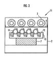
- Example 3 an aggregate of the multilayered carbon nanotubes obtained in exactly the same manner as in Example 1 were irradiated as a raw carbon nanotubes with an ultraviolet ray using an ultraviolet irradiation apparatus 11 shown in FIG. 3.
- the ultraviolet irradiation apparatus 11 shown in FIG. 3 has the same constitution as the ultraviolet irradiation apparatus 1 except that rotating platform 13 which pivotally supports a plurality of rotors 12 parallel-arranged in the horizontal direction is provided instead of sample stage 5. Respective rotors 12 rotate mutually synchronously by motors not shown in the figure and pipes 14 made of synthetic quartz glass containing raw carbon nanotubes (not shown in the figure) are placed between the rotors 12 and 12 and irradiated with an ultraviolet ray by means of ultraviolet lamp 3. Each pipe 14 made of synthetic quartz glass possesses regulating valves for regulating the inner atmosphere at the closed both end parts thereof.
- the ultraviolet irradiation apparatus 11 since the pipes 14 can be rotated, the raw carbon nanotubes are stirred in pipes 14 and the carbon nanotubes can be homogeneously irradiated with the ultraviolet ray. Moreover, pipes 14 are placed in chamber 2 but the inside of pipes 14 is separated from the atmosphere of chamber 2. Therefore, the inside of chamber 2 can be an inert atmosphere such as nitrogen, while the inside of pipes 14 may be an atmosphere of air. By making the inside of chamber 2 an inert atmosphere, the attenuation of photon energy of the ultraviolet ray before the ultraviolet ray reaches the carbon nanotubes can be suppressed and thus this case is preferred.
- hydrophilic carbon nanotubes were produced by irradiation with an ultraviolet ray having a wavelength of 172 nm using a xenon gas-included dielectric barrier discharge excimer lamp manufactured by Ushio Inc. as ultraviolet lamp 3.
- the ultraviolet ray was applied under conditions of an output of 58 mW/cm 2 and an irradiation distance of 50 mm for 300 seconds.
- the irradiation distance is a distance between the outer surface of ultraviolet lamp 3 and the outer surface of pipe 14.
- a contact angle ⁇ was measured in exactly the same manner as in Example 1 except that an aggregate of carbon nanotubes 4 obtained in exactly the same manner as in Example 1 without irradiation with any ultraviolet ray was used.
- the distilled water dropped on the surface of the disk of the hydrophilic carbon nanotubes did not soak into the above disk and the contact angle ⁇ was found to be 132°. The results are shown in Table 1.
- the contact angle ⁇ of water toward carbon nanotube 4 is 130° or more when raw carbon nanotubes 4 are not irradiated with any ultraviolet ray.
- the contact angle ⁇ of water toward carbon nanotubes 4 is 110° or less and thus it is apparent that hydrophilic carbon nanotubes are obtained.
Landscapes
- Chemical & Material Sciences (AREA)
- Engineering & Computer Science (AREA)
- Nanotechnology (AREA)
- Materials Engineering (AREA)
- Organic Chemistry (AREA)
- Physics & Mathematics (AREA)
- Chemical Kinetics & Catalysis (AREA)
- Condensed Matter Physics & Semiconductors (AREA)
- Inorganic Chemistry (AREA)
- General Physics & Mathematics (AREA)
- Crystallography & Structural Chemistry (AREA)
- Electromagnetism (AREA)
- Health & Medical Sciences (AREA)
- General Health & Medical Sciences (AREA)
- Toxicology (AREA)
- Manufacturing & Machinery (AREA)
- Composite Materials (AREA)
- Carbon And Carbon Compounds (AREA)
Applications Claiming Priority (2)
| Application Number | Priority Date | Filing Date | Title |
|---|---|---|---|
| JP2004085558 | 2004-03-23 | ||
| JP2004085558A JP2005272184A (ja) | 2004-03-23 | 2004-03-23 | 親水性カーボンナノチューブの製造方法 |
Publications (2)
| Publication Number | Publication Date |
|---|---|
| EP1580165A1 true EP1580165A1 (de) | 2005-09-28 |
| EP1580165B1 EP1580165B1 (de) | 2010-10-20 |
Family
ID=34858421
Family Applications (1)
| Application Number | Title | Priority Date | Filing Date |
|---|---|---|---|
| EP05251799A Expired - Lifetime EP1580165B1 (de) | 2004-03-23 | 2005-03-23 | Verfahren zur Herstellung von hydrophilen Kohlenstoffnanoröhren |
Country Status (4)
| Country | Link |
|---|---|
| US (1) | US7553471B2 (de) |
| EP (1) | EP1580165B1 (de) |
| JP (1) | JP2005272184A (de) |
| DE (1) | DE602005024206D1 (de) |
Cited By (3)
| Publication number | Priority date | Publication date | Assignee | Title |
|---|---|---|---|---|
| EP2055672A4 (de) * | 2006-08-21 | 2010-10-13 | Fujitsu Ltd | N-halbleiter-kohlenstoffnanomaterial, verfahren zur herstellung von n-halbleiter-kohlenstoffnanomaterial und verfahren zur herstellung einer halbleitervorrichtung |
| CN109851363A (zh) * | 2019-01-31 | 2019-06-07 | 中南大学 | 一种带梯度界面层的含异质元素SiC纤维及其制备方法和设备 |
| RU2707930C1 (ru) * | 2018-05-31 | 2019-12-02 | Федеральное государственное бюджетное образовательное учреждение высшего образования "Московский государственный университет имени М.В.Ломоносова" (МГУ) | Способ модификации углеродных нанотрубок для получения гидрофильных или гидрофобных поверхностей |
Families Citing this family (28)
| Publication number | Priority date | Publication date | Assignee | Title |
|---|---|---|---|---|
| US9056783B2 (en) | 1998-12-17 | 2015-06-16 | Hach Company | System for monitoring discharges into a waste water collection system |
| US8958917B2 (en) | 1998-12-17 | 2015-02-17 | Hach Company | Method and system for remote monitoring of fluid quality and treatment |
| US7454295B2 (en) | 1998-12-17 | 2008-11-18 | The Watereye Corporation | Anti-terrorism water quality monitoring system |
| US6723299B1 (en) | 2001-05-17 | 2004-04-20 | Zyvex Corporation | System and method for manipulating nanotubes |
| US6905667B1 (en) | 2002-05-02 | 2005-06-14 | Zyvex Corporation | Polymer and method for using the polymer for noncovalently functionalizing nanotubes |
| US20040034177A1 (en) | 2002-05-02 | 2004-02-19 | Jian Chen | Polymer and method for using the polymer for solubilizing nanotubes |
| US8920619B2 (en) | 2003-03-19 | 2014-12-30 | Hach Company | Carbon nanotube sensor |
| KR100827861B1 (ko) | 2003-05-22 | 2008-05-07 | 지벡스 퍼포먼스 머티리얼즈, 엘엘씨 | 나노복합물 및 이의 제조 방법 |
| US8309112B2 (en) * | 2003-12-24 | 2012-11-13 | Advanced Cardiovascular Systems, Inc. | Coatings for implantable medical devices comprising hydrophilic substances and methods for fabricating the same |
| US7296576B2 (en) | 2004-08-18 | 2007-11-20 | Zyvex Performance Materials, Llc | Polymers for enhanced solubility of nanomaterials, compositions and methods therefor |
| CA2584433A1 (en) * | 2004-10-22 | 2006-12-21 | Hyperion Catalysis International, Inc. | Improved ozonolysis of carbon nanotubes |
| US20080093211A1 (en) * | 2005-12-27 | 2008-04-24 | Rensselaer Polytechnic Institute | Method for site-selective functionalization of carbon nanotubes and uses thereof |
| US8048275B2 (en) * | 2006-01-20 | 2011-11-01 | Kyushu University, National University Corporation | Method of solubilizing carbon nanomaterial |
| CN100364885C (zh) * | 2006-03-09 | 2008-01-30 | 同济大学 | 亲水亲油性碳纳米管的制备方法 |
| US7807127B1 (en) | 2006-04-14 | 2010-10-05 | The United States Of America As Represented By The Secretary Of The Navy | Functionalization of carbon nanotubes |
| US7794683B1 (en) | 2006-04-14 | 2010-09-14 | The United States Of America As Represented By The Secretary Of The Navy | Method of making functionalized carbon nanotubes |
| JP5099010B2 (ja) * | 2006-08-21 | 2012-12-12 | 富士通株式会社 | n型半導体カーボンナノ材料の製造方法および半導体装置の製造方法 |
| WO2008026237A1 (fr) * | 2006-08-28 | 2008-03-06 | Fujitsu Limited | Matériaux à base de nanotubes de carbone, procédé de production et dispositif et composants électroniques |
| US20080152573A1 (en) * | 2006-12-20 | 2008-06-26 | Noriyuki Juni | Method for producing carbon nanotubes, method for producing liquid dispersion thereof and optical product |
| JP4999072B2 (ja) * | 2007-03-22 | 2012-08-15 | 古河電気工業株式会社 | 表面被覆材 |
| US7843695B2 (en) * | 2007-07-20 | 2010-11-30 | Honeywell International Inc. | Apparatus and method for thermal management using vapor chamber |
| JP5066743B2 (ja) * | 2008-01-29 | 2012-11-07 | 三菱電機株式会社 | メッキ方法およびその方法により製造されたメッキ皮膜を備えたメッキ品 |
| KR100998184B1 (ko) | 2008-03-27 | 2010-12-03 | 한국원자력연구원 | 함산소불소처리된 탄소나노재료 및 방사선을 이용한 열적기계적 특성이 향상된 에폭시 경화수지의 제조방법 |
| US8304143B2 (en) * | 2008-11-25 | 2012-11-06 | GM Global Technology Operations LLC | Conductive and hydrophilic coating for PEMFC bipolar plate |
| JP2010243036A (ja) * | 2009-04-03 | 2010-10-28 | Sony Corp | 熱輸送装置、電子機器及び熱輸送装置の製造方法 |
| CA2712051A1 (en) * | 2010-08-12 | 2012-02-12 | The Governors Of The University Of Alberta | Method of fabricating a carbon nanotube array |
| US8491970B2 (en) * | 2010-09-29 | 2013-07-23 | Teledyne Scientific & Imaging, Llc | Vertically aligned carbon nanotube arrays from liquid dispersions |
| JP5884376B2 (ja) * | 2011-09-30 | 2016-03-15 | 三菱マテリアル株式会社 | カーボンナノファイバー、およびカーボンナノファイバー分散液 |
Citations (1)
| Publication number | Priority date | Publication date | Assignee | Title |
|---|---|---|---|---|
| US20050036905A1 (en) * | 2003-08-12 | 2005-02-17 | Matsushita Electric Works, Ltd. | Defect controlled nanotube sensor and method of production |
Family Cites Families (12)
| Publication number | Priority date | Publication date | Assignee | Title |
|---|---|---|---|---|
| JPS60149114A (ja) * | 1984-01-13 | 1985-08-06 | 松下電器産業株式会社 | キヤパシタまたは電池用電極の製造法 |
| JPH01183575A (ja) * | 1988-01-19 | 1989-07-21 | Osaka Gas Co Ltd | 炭素繊維の表面処理方法 |
| JP2755431B2 (ja) * | 1989-05-31 | 1998-05-20 | 科学技術振興事業団 | 炭素繊維強化炭素複合材料 |
| US6203814B1 (en) | 1994-12-08 | 2001-03-20 | Hyperion Catalysis International, Inc. | Method of making functionalized nanotubes |
| JP2639371B2 (ja) * | 1995-01-30 | 1997-08-13 | 日本電気株式会社 | 液晶材料およびその合成方法 |
| JP2001118818A (ja) * | 1999-08-12 | 2001-04-27 | Uct Kk | 紫外線処理装置及び紫外線処理方法 |
| WO2003084865A2 (en) * | 2001-06-14 | 2003-10-16 | Hyperion Catalysis International, Inc. | Field emission devices using modified carbon nanotubes |
| JP3930276B2 (ja) * | 2001-08-29 | 2007-06-13 | 株式会社Gsiクレオス | 気相成長法による炭素繊維、リチウム二次電池用電極材およびリチウム二次電池 |
| US7317277B2 (en) * | 2002-04-24 | 2008-01-08 | E.I. Du Pont De Nemours And Company | Electron field emitter and compositions related thereto |
| JP2004345918A (ja) * | 2003-05-23 | 2004-12-09 | Sharp Corp | カーボンナノチューブの精製方法 |
| JP2004362919A (ja) * | 2003-06-04 | 2004-12-24 | Hitachi Zosen Corp | カーボンナノチューブを用いた電子放出素子の製造方法 |
| US7122165B2 (en) * | 2003-11-03 | 2006-10-17 | The Research Foundation Of State University Of New York | Sidewall-functionalized carbon nanotubes, and methods for making the same |
-
2004
- 2004-03-23 JP JP2004085558A patent/JP2005272184A/ja active Pending
-
2005
- 2005-03-23 US US11/088,320 patent/US7553471B2/en not_active Expired - Fee Related
- 2005-03-23 EP EP05251799A patent/EP1580165B1/de not_active Expired - Lifetime
- 2005-03-23 DE DE602005024206T patent/DE602005024206D1/de not_active Expired - Lifetime
Patent Citations (1)
| Publication number | Priority date | Publication date | Assignee | Title |
|---|---|---|---|---|
| US20050036905A1 (en) * | 2003-08-12 | 2005-02-17 | Matsushita Electric Works, Ltd. | Defect controlled nanotube sensor and method of production |
Non-Patent Citations (4)
| Title |
|---|
| CUI J ET AL: "Reversible sidewall osmylation of individual carbon nanotubes", NANO LETTERS AMERICAN CHEM. SOC USA, vol. 3, no. 5, May 2003 (2003-05-01), pages 613 - 615, XP002331780, ISSN: 1530-6984 * |
| KIM J S ET AL: "Ultraviolet laser treatment of multiwall carbon nanotubes grown at low temperature", APPLIED PHYSICS LETTERS, AMERICAN INSTITUTE OF PHYSICS. NEW YORK, US, vol. 82, no. 10, 10 March 2003 (2003-03-10), pages 1607 - 1609, XP012033494, ISSN: 0003-6951 * |
| SAVAGE T ET AL: "Photoinduced oxidation of carbon nanotubes", JOURNAL OF PHYSICS: CONDENSED MATTER IOP PUBLISHING UK, vol. 15, no. 35, 10 September 2003 (2003-09-10), pages 5915 - 5921, XP002331779, ISSN: 0953-8984 * |
| ZHAO W-J ET AL: "FIELD EMISSION CHARACTERISTICS OF SCREEN-PRINTED CARBON NANOTUBE AFTER LASER IRRADIATION", JAPANESE JOURNAL OF APPLIED PHYSICS, PUBLICATION OFFICE JAPANESE JOURNAL OF APPLIED PHYSICS. TOKYO, JP, vol. 41, no. 6B, PART 1, June 2002 (2002-06-01), pages 4314 - 4316, XP001163422, ISSN: 0021-4922 * |
Cited By (4)
| Publication number | Priority date | Publication date | Assignee | Title |
|---|---|---|---|---|
| EP2055672A4 (de) * | 2006-08-21 | 2010-10-13 | Fujitsu Ltd | N-halbleiter-kohlenstoffnanomaterial, verfahren zur herstellung von n-halbleiter-kohlenstoffnanomaterial und verfahren zur herstellung einer halbleitervorrichtung |
| RU2707930C1 (ru) * | 2018-05-31 | 2019-12-02 | Федеральное государственное бюджетное образовательное учреждение высшего образования "Московский государственный университет имени М.В.Ломоносова" (МГУ) | Способ модификации углеродных нанотрубок для получения гидрофильных или гидрофобных поверхностей |
| CN109851363A (zh) * | 2019-01-31 | 2019-06-07 | 中南大学 | 一种带梯度界面层的含异质元素SiC纤维及其制备方法和设备 |
| CN109851363B (zh) * | 2019-01-31 | 2021-08-27 | 中南大学 | 一种带梯度界面层的含异质元素SiC纤维及其制备方法和设备 |
Also Published As
| Publication number | Publication date |
|---|---|
| US7553471B2 (en) | 2009-06-30 |
| US20050214196A1 (en) | 2005-09-29 |
| JP2005272184A (ja) | 2005-10-06 |
| EP1580165B1 (de) | 2010-10-20 |
| DE602005024206D1 (de) | 2010-12-02 |
Similar Documents
| Publication | Publication Date | Title |
|---|---|---|
| EP1580165A1 (de) | Verfahren zur Herstellung von hydrophilen Kohlenstoffnanoröhren | |
| Branca et al. | Characterization of carbon nanotubes by TEM and infrared spectroscopy | |
| KR101443217B1 (ko) | 그라펜 쉘 및 그의 제조방법 | |
| CN100368287C (zh) | 单壁碳质毫微管有助于其溶剂化的化学衍生化以及经衍生化毫微管的用途 | |
| JP7078038B2 (ja) | 繊維状炭素ナノ構造体分散液及びその製造方法、並びに繊維状炭素ナノ構造体 | |
| WO2005052053A1 (ja) | カーボンナノチューブ分散極性有機溶媒及びその製造方法 | |
| BRPI0618737B1 (pt) | Nanotubo de carbono fulereno-funcionalizado, método para produzir um ou mais nanotubos de carbono fulereno-funcionalizado, material funcional, película espessa ou fina, uma linha, um fio ou uma estrutura em camadas ou tridimensional, e, dispositivo | |
| CN106660804B (zh) | 石墨烯制造工艺 | |
| JP2005263607A (ja) | Cnt表面改質方法およびcnt | |
| JP4931168B2 (ja) | 高純度2層〜5層カーボンナノチューブの製造方法 | |
| Alamri et al. | Enhanced H₂ sensitivity in ultraviolet-activated Pt nanoparticle/SWCNT/graphene nanohybrids | |
| JP5515293B2 (ja) | カーボンナノ材料の壁面開孔方法およびカーボンナノ材料の開孔への酸素含有基導入方法 | |
| Shojaei et al. | Fabrication, functionalization, and dispersion of carbon nanotubes | |
| JP6922893B2 (ja) | 吸着材 | |
| US20020150529A1 (en) | Single-wall carbon nanotubes for hydrogen storage or superbundle formation | |
| CN107089652A (zh) | 窄带隙分布、高纯度半导体性单壁碳纳米管的制备方法 | |
| US11661345B2 (en) | Fibrous carbon nanostructure, method of producing fibrous carbon nanostructure, and method of producing surface-modified fibrous carbon nanostructure | |
| WO2019124026A1 (ja) | 繊維状炭素ナノ構造体、繊維状炭素ナノ構造体の評価方法および表面改質繊維状炭素ナノ構造体の製造方法 | |
| JP7632439B2 (ja) | 窒化ホウ素ナノチューブ製造用窒化ホウ素ナノチューブ混合液 | |
| Fan et al. | Preparation and characterization of functional multi-walled carbon nanotubes (MWCNTs) through acidification and radiation induced graft polymerization | |
| AU4313901A (en) | Single-wall carbon nanotubes for hydrogen storage or superbundle formation | |
| Han et al. | Field emission and growth characteristics of carbon nanotubes with optical emission spectroscopy analysis in C 3 H 4 and CO deposition systems | |
| Choi | The Effect of Surface Properties of Carbon Nanomaterials on the Molecular Adsorption of Organophosphate | |
| Bittencourt et al. | Evaporation of WO3 on carbon nanotube films: a new hybrid film | |
| Komukai et al. | Structural analysis of high-density vertically aligned carbon nanotubes grown by thermal chemical vapor deposition with Fe/Al multilayer catalyst |
Legal Events
| Date | Code | Title | Description |
|---|---|---|---|
| PUAI | Public reference made under article 153(3) epc to a published international application that has entered the european phase |
Free format text: ORIGINAL CODE: 0009012 |
|
| AK | Designated contracting states |
Kind code of ref document: A1 Designated state(s): AT BE BG CH CY CZ DE DK EE ES FI FR GB GR HU IE IS IT LI LT LU MC NL PL PT RO SE SI SK TR |
|
| AX | Request for extension of the european patent |
Extension state: AL BA HR LV MK YU |
|
| 17P | Request for examination filed |
Effective date: 20050902 |
|
| AKX | Designation fees paid |
Designated state(s): DE FR GB |
|
| GRAP | Despatch of communication of intention to grant a patent |
Free format text: ORIGINAL CODE: EPIDOSNIGR1 |
|
| GRAS | Grant fee paid |
Free format text: ORIGINAL CODE: EPIDOSNIGR3 |
|
| GRAA | (expected) grant |
Free format text: ORIGINAL CODE: 0009210 |
|
| AK | Designated contracting states |
Kind code of ref document: B1 Designated state(s): DE FR GB |
|
| REG | Reference to a national code |
Ref country code: GB Ref legal event code: FG4D |
|
| REF | Corresponds to: |
Ref document number: 602005024206 Country of ref document: DE Date of ref document: 20101202 Kind code of ref document: P |
|
| PLBE | No opposition filed within time limit |
Free format text: ORIGINAL CODE: 0009261 |
|
| STAA | Information on the status of an ep patent application or granted ep patent |
Free format text: STATUS: NO OPPOSITION FILED WITHIN TIME LIMIT |
|
| 26N | No opposition filed |
Effective date: 20110721 |
|
| REG | Reference to a national code |
Ref country code: DE Ref legal event code: R097 Ref document number: 602005024206 Country of ref document: DE Effective date: 20110721 |
|
| PGFP | Annual fee paid to national office [announced via postgrant information from national office to epo] |
Ref country code: DE Payment date: 20130320 Year of fee payment: 9 Ref country code: FR Payment date: 20130325 Year of fee payment: 9 Ref country code: GB Payment date: 20130320 Year of fee payment: 9 |
|
| REG | Reference to a national code |
Ref country code: DE Ref legal event code: R119 Ref document number: 602005024206 Country of ref document: DE |
|
| GBPC | Gb: european patent ceased through non-payment of renewal fee |
Effective date: 20140323 |
|
| REG | Reference to a national code |
Ref country code: FR Ref legal event code: ST Effective date: 20141128 |
|
| REG | Reference to a national code |
Ref country code: DE Ref legal event code: R119 Ref document number: 602005024206 Country of ref document: DE Effective date: 20141001 |
|
| PG25 | Lapsed in a contracting state [announced via postgrant information from national office to epo] |
Ref country code: FR Free format text: LAPSE BECAUSE OF NON-PAYMENT OF DUE FEES Effective date: 20140331 Ref country code: DE Free format text: LAPSE BECAUSE OF NON-PAYMENT OF DUE FEES Effective date: 20141001 Ref country code: GB Free format text: LAPSE BECAUSE OF NON-PAYMENT OF DUE FEES Effective date: 20140323 |