EP1580336A2 - Dispositif d'arrêt pour la prevention des fuites - Google Patents
Dispositif d'arrêt pour la prevention des fuites Download PDFInfo
- Publication number
- EP1580336A2 EP1580336A2 EP05005791A EP05005791A EP1580336A2 EP 1580336 A2 EP1580336 A2 EP 1580336A2 EP 05005791 A EP05005791 A EP 05005791A EP 05005791 A EP05005791 A EP 05005791A EP 1580336 A2 EP1580336 A2 EP 1580336A2
- Authority
- EP
- European Patent Office
- Prior art keywords
- water
- leaks
- domestic
- prevent
- water flow
- Prior art date
- Legal status (The legal status is an assumption and is not a legal conclusion. Google has not performed a legal analysis and makes no representation as to the accuracy of the status listed.)
- Withdrawn
Links
- XLYOFNOQVPJJNP-UHFFFAOYSA-N water Substances O XLYOFNOQVPJJNP-UHFFFAOYSA-N 0.000 claims abstract description 55
- 230000002035 prolonged effect Effects 0.000 claims abstract description 3
- 238000002604 ultrasonography Methods 0.000 claims description 6
- 230000006870 function Effects 0.000 description 2
- 206010001488 Aggression Diseases 0.000 description 1
- 238000010276 construction Methods 0.000 description 1
- 230000004048 modification Effects 0.000 description 1
- 238000012986 modification Methods 0.000 description 1
- 238000000926 separation method Methods 0.000 description 1
- 230000000007 visual effect Effects 0.000 description 1
Images



Classifications
-
- E—FIXED CONSTRUCTIONS
- E03—WATER SUPPLY; SEWERAGE
- E03B—INSTALLATIONS OR METHODS FOR OBTAINING, COLLECTING, OR DISTRIBUTING WATER
- E03B7/00—Water main or service pipe systems
- E03B7/07—Arrangement of devices, e.g. filters, flow controls, measuring devices, siphons or valves, in the pipe systems
- E03B7/072—Arrangement of flowmeters
-
- E—FIXED CONSTRUCTIONS
- E03—WATER SUPPLY; SEWERAGE
- E03B—INSTALLATIONS OR METHODS FOR OBTAINING, COLLECTING, OR DISTRIBUTING WATER
- E03B7/00—Water main or service pipe systems
- E03B7/07—Arrangement of devices, e.g. filters, flow controls, measuring devices, siphons or valves, in the pipe systems
- E03B7/071—Arrangement of safety devices in domestic pipe systems, e.g. devices for automatic shut-off
-
- Y—GENERAL TAGGING OF NEW TECHNOLOGICAL DEVELOPMENTS; GENERAL TAGGING OF CROSS-SECTIONAL TECHNOLOGIES SPANNING OVER SEVERAL SECTIONS OF THE IPC; TECHNICAL SUBJECTS COVERED BY FORMER USPC CROSS-REFERENCE ART COLLECTIONS [XRACs] AND DIGESTS
- Y02—TECHNOLOGIES OR APPLICATIONS FOR MITIGATION OR ADAPTATION AGAINST CLIMATE CHANGE
- Y02A—TECHNOLOGIES FOR ADAPTATION TO CLIMATE CHANGE
- Y02A20/00—Water conservation; Efficient water supply; Efficient water use
- Y02A20/15—Leakage reduction or detection in water storage or distribution
Definitions
- the invention refers to a safe device with an one's own energy duration having the aim to stop the water flow in the case of its consumption protracted in time.
- protracted consumption any water use actuated in the domestic of industrial waterworks for a time longer than the setting one. So, a water leak out of control is part of said situation such as the water flow is continuous opened whereas in the normal use by means of taps the water outflow is inside a determined time and to be estimated in the single cases but always limited in time.
- the invented device is able to determine an action time of itself with electronic apparatuses set in the setting time and with apparatuses able to determine the closing of the water flow that remain in closing till they are manually put again in action.
- the invented device In the use with time shorter than the setting out time, the invented device lets to run the flow automatically clearing the past time count.
- the setting out of the action time is fixed to the users on the base of the necessities and to the waterworks uses.
- the invented device is to be mounted immediately downhill to the water counter so to control all the waterworks, also if it has big dimension and different ramifications.
- the present safety devices known in the prior art, limit themselves to signal the getting over of the fixed time by the action of a audible and luminous detector and they must be fed to electric energy coming to power (at 220 Volt) so making they use of difficult application and with high costs to actuate the plant. Infact, to wire a plant that connects the water well with the building has bigger costs than the devices in use for these applications.
- the present invention has the aim to principally eliminated this problem, providing the invented device of energy duration determined to a turbine connected in axis to an alternator with magnetic sensors and long life battery and which exploits the water flow passing inside the piping to recharge said battery.
- This and other aims, as to take the water consumption for each use and for the total consumption, are obtained to the invented device.
- the device following described is illustrated in a merely indicative and not limiting way in the enclosed sheets 1, 2, 3, 4 and 5 that show an application form not exclusive.
- sheet 1 figure 1 is longitudinal view of the main components of the invented device closed inside a hermetic seal casing 10.
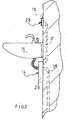
- figure 2 is lateral view of the application of parts of the flow counter with, over the wash-basin 15, a containing body 16 for the display 28 of the water consumption and, placed under the same wash-basin, a casing 14 for the acoustic signal amplifier 26, with the water piping 18 joined to the taps of the wash-basin.
- sheet 3 figure 3 is view of an example of application of the invented device with water well 21 and water counter 19 out of the building. Said water counter is generally given to the company that supplies the service of water furniture.
- sheet 4 figure 4 is view of the components electric scheme and of the plant connections.
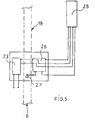
- sheet 5 figure 5 is view of the electric scheme of part of the counter device of the water consumption.
- the invented device is started to the kinetic energy of the water flow 8 that puts in rotation the turbine 3 to which in axis an alternator 4 and moving magnetic sensors 5 are connected.
- the alternator 4 and a very long life battery, placed in the circuit give the electric energy necessary to the function of the device for an unlimited time.
- the water flow 8 puts in movement the alternator 4 and the sensors 5 connected to the electronic circuit 11 by means of cables connect to the clamps 11B, which connect the electronic circuit 11 to the moving magnetic sensors 5, and the clamps 11C that connect the feeder 23 and the circuit 11 to the sensors 5 placed on the alternator 4, so to determine the closing and the opening of the electronic circuit 11.
- the use of the sensors 5 derives to better safety reasons, to determine the stop or the closing of the electronic circuit 11, connected to the timer 22, provided to measure the running time of the water flow 8, such as the half-waves created to the alternator 4 are also directly red to the adjustable timer 22 and they are a sufficient signal to let start the running time count of the water flow 8.
- the timer 22 present inside the electronic circuit 11 is induced to measure the time starting from the first opening moment of the water flow 8 coming into the safety device and going out to the outflow 9 connected to the water piping 18.
- the adjustable timer 22 stops its count at the stopping of the water flow 8 detected to the moving magnetic sensors 5 and/or to the non-production of the half-waves created to the alternator 4.
- each opening of the taps and consequently of the water flow 8 for lower times in comparison with the setting out time automatically determines the zero deflection of the running time count, actuated by the adjustable timer 22 with memory and with time comparison device.
- a control circuit inside the electronic circuit 11 with impulse coming to the timer 22, gives tension to the clamps 11A and to the connected cables so determining the disarming of the eiecnovalve 1 with consequent stop of the water flow 8.
- the device enters in function only to the reachiog of the setting out time so determining the please of the electrovalve 1 that, to be in condition to work again, must be manually rearmed by means of the arming device 2.
- the device moreover comprises an orifice plate 6 to separate the water flow and the alternator, of a casing 7 for the acoustic modulator 24 and of an acoustic transducer 27 to indicate to the user the water consumption to determined quantities or a water leak in the waterworks.
- the moving magnetic sensors 5, applied in axis to the turbine 3, permit to directly proportion the alternations number to the quantity of passing flow.
- the number of altercations sent to an adder 25, present in the electronic circuit 11, permits to know the water, quantity runs inside the invented device.
- Said adder 25, present in the electronic circuit 11, is not a totalizator but a device to sign to the acoustic modulator 24, i.e. an ultrasounds generator inside the water flow that runs in the piping, the delivery of each cubic meter to of used water from the user and the total water consumption.
- the adder 25 gives an impulse to the acoustic modulator 24 that creates a signal traduced in ultrasounds to the same modulator 24 by the circuit 12 and that is sent along the water flow present in the piping.
- Said ultrasounds signal is then received to the acoustic signal amplifier 26 that transforms said signal in an electric signal to be transmitted to the acoustic transducer 27 and/or to the totalizator display 28 where the user can read the water consumption.
- the acoustic modulator 24 is connected to the amplifier 26 by means of cables and clamps 11E and the amplifier 26 is connected to the acoustic transducer 27 and/or to the display 28 by cables and clamps 11D.
- the working of water consumption meter, other aim of the invention, is to be actuated in absence of connection with the electric power but, this absence is not indispensable, such as inside the buildings is present an electric connection 17.
- the invented device is inside a containing body 20 into which are placed the long life batteries and the hermetic seal casing 10 for the electric components.
- the invented device on the base of that above described, is to be used without electric connection and it intervenes stopping the delivery of the water flow in case of water leak in every point of the waterworks or for a tap lets opening, such as these cases make part of the prolonged use, giving contemporary the possibility to visual and to know the water consumption.
- the dimensions and the shapes of the invented device are to be changed remaining in the inventive concept of the present invention.
- the present described and illustrated device can have modifications or variations entering in the present inventive concept and all the components are changing with other technically equivalent
Landscapes
- Health & Medical Sciences (AREA)
- Life Sciences & Earth Sciences (AREA)
- Engineering & Computer Science (AREA)
- Hydrology & Water Resources (AREA)
- Public Health (AREA)
- Water Supply & Treatment (AREA)
- Domestic Plumbing Installations (AREA)
- Measuring Volume Flow (AREA)
Priority Applications (1)
| Application Number | Priority Date | Filing Date | Title |
|---|---|---|---|
| EP05005791A EP1580336A3 (fr) | 2005-03-17 | 2005-03-17 | Dispositif d'arrêt pour la prevention des fuites |
Applications Claiming Priority (2)
| Application Number | Priority Date | Filing Date | Title |
|---|---|---|---|
| ITRO20040002 | 2004-03-18 | ||
| EP05005791A EP1580336A3 (fr) | 2005-03-17 | 2005-03-17 | Dispositif d'arrêt pour la prevention des fuites |
Publications (2)
| Publication Number | Publication Date |
|---|---|
| EP1580336A2 true EP1580336A2 (fr) | 2005-09-28 |
| EP1580336A3 EP1580336A3 (fr) | 2006-06-28 |
Family
ID=34856967
Family Applications (1)
| Application Number | Title | Priority Date | Filing Date |
|---|---|---|---|
| EP05005791A Withdrawn EP1580336A3 (fr) | 2005-03-17 | 2005-03-17 | Dispositif d'arrêt pour la prevention des fuites |
Country Status (1)
| Country | Link |
|---|---|
| EP (1) | EP1580336A3 (fr) |
Cited By (3)
| Publication number | Priority date | Publication date | Assignee | Title |
|---|---|---|---|---|
| GB2516770A (en) * | 2013-07-26 | 2015-02-04 | Gerard Duffy | Apparatus and method for reducing water wastage |
| GB2559587A (en) * | 2017-02-10 | 2018-08-15 | Radford Alan | Apparatus for limiting leakage from a liquid supply installation in a premises |
| ES2688730A1 (es) * | 2017-05-04 | 2018-11-06 | Juan Luis Abad Clarimon | Economizador de consumo de agua corriente sanitaria |
Family Cites Families (5)
| Publication number | Priority date | Publication date | Assignee | Title |
|---|---|---|---|---|
| US3750001A (en) * | 1969-11-28 | 1973-07-31 | E Mccloskey | Remote, completely self-contained, self-maintaining power supply apparatus for powering a pressurized-liquid distributing and disseminating system |
| FR2653554A1 (fr) * | 1989-10-23 | 1991-04-26 | Roche Jean | Compteur electronique d'eau permettant d'effectuer un releve des consommations a distance. |
| US5979493A (en) * | 1996-08-02 | 1999-11-09 | Gary A. Isaacson, Jr. | Flood control device |
| DE29812659U1 (de) * | 1998-07-16 | 1998-11-19 | Schrage, Uwe, 34388 Trendelburg | Vorrichtung zur Anbringung an einer Wasserabgabeeinrichtung |
| DE20019814U1 (de) * | 2000-11-22 | 2001-02-08 | Aigner, Tilo, 08396 Waldenburg | Zentrale Wassersicherung |
-
2005
- 2005-03-17 EP EP05005791A patent/EP1580336A3/fr not_active Withdrawn
Cited By (4)
| Publication number | Priority date | Publication date | Assignee | Title |
|---|---|---|---|---|
| GB2516770A (en) * | 2013-07-26 | 2015-02-04 | Gerard Duffy | Apparatus and method for reducing water wastage |
| GB2516770B (en) * | 2013-07-26 | 2018-02-28 | Duffy Gerard | Apparatus and method for reducing water wastage |
| GB2559587A (en) * | 2017-02-10 | 2018-08-15 | Radford Alan | Apparatus for limiting leakage from a liquid supply installation in a premises |
| ES2688730A1 (es) * | 2017-05-04 | 2018-11-06 | Juan Luis Abad Clarimon | Economizador de consumo de agua corriente sanitaria |
Also Published As
| Publication number | Publication date |
|---|---|
| EP1580336A3 (fr) | 2006-06-28 |
Similar Documents
| Publication | Publication Date | Title |
|---|---|---|
| US20090194719A1 (en) | Fluid supply monitoring system | |
| US20080185049A1 (en) | Fluid supply monitoring system | |
| US6708722B1 (en) | Water flow control system | |
| EP0836690B1 (fr) | Dispositif de prevention des inondations | |
| US5979493A (en) | Flood control device | |
| AU2007307631B2 (en) | Water conservation safety shut-off valve | |
| AU2013361191B2 (en) | Water meter systems and methods | |
| US7549322B2 (en) | System and method for detecting a leak in a piping system | |
| WO2006110600A2 (fr) | Systeme et procede de surveillance, d'enregistrement et de facturation d'un appareil sanitaire individuel et unite d'utilisation de l'eau dans une structure multi-unite | |
| EP2982891A2 (fr) | Soupape d'arrêt de sécurité d'eau | |
| ATE240074T1 (de) | Vorrichtung zur überwachung der funktion einer sich drehenden, flüssigkeit abgebenden einrichtung | |
| JPH06341917A (ja) | 流量検出装置 | |
| EP1355132A3 (fr) | Débitmètre massique adaptable | |
| AU2010342810B2 (en) | Water waste detection in water distribution system with piezoelectric device | |
| IE20140180A1 (en) | Apparatus and method for reducing water wastage | |
| EP0950877A3 (fr) | Compteur compact de liquide | |
| CN102117077A (zh) | 流量监控装置 | |
| JP3263044B2 (ja) | 漏水監視装置 | |
| WO2018104756A1 (fr) | Système de mesure et de commande d'alimentation en eau | |
| CN209330878U (zh) | 一种养殖业自动供水机械设备 | |
| JP2002372442A (ja) | 水道メーター | |
| JP2008256535A (ja) | ガス遮断装置 | |
| TW201409009A (zh) | 漏水偵測水表及其漏水偵測方法 | |
| CN219606774U (zh) | 一种输水管道用水锤现象早期告警装置 | |
| JP2008111696A (ja) | 流量計測装置および流体供給システム |
Legal Events
| Date | Code | Title | Description |
|---|---|---|---|
| PUAI | Public reference made under article 153(3) epc to a published international application that has entered the european phase |
Free format text: ORIGINAL CODE: 0009012 |
|
| AK | Designated contracting states |
Kind code of ref document: A2 Designated state(s): AT BE BG CH CY CZ DE DK EE ES FI FR GB GR HU IE IS IT LI LT LU MC NL PL PT RO SE SI SK TR |
|
| AX | Request for extension of the european patent |
Extension state: AL BA HR LV MK YU |
|
| RIC1 | Information provided on ipc code assigned before grant |
Ipc: 7E 03B 7/07 B Ipc: 7G 01F 15/06 B Ipc: 7G 01F 15/00 A |
|
| PUAL | Search report despatched |
Free format text: ORIGINAL CODE: 0009013 |
|
| AK | Designated contracting states |
Kind code of ref document: A3 Designated state(s): AT BE BG CH CY CZ DE DK EE ES FI FR GB GR HU IE IS IT LI LT LU MC NL PL PT RO SE SI SK TR |
|
| AX | Request for extension of the european patent |
Extension state: AL BA HR LV MK YU |
|
| AKX | Designation fees paid | ||
| REG | Reference to a national code |
Ref country code: DE Ref legal event code: 8566 |
|
| STAA | Information on the status of an ep patent application or granted ep patent |
Free format text: STATUS: THE APPLICATION IS DEEMED TO BE WITHDRAWN |
|
| 18D | Application deemed to be withdrawn |
Effective date: 20061229 |