EP1580389A2 - Joint d'angle - Google Patents
Joint d'angle Download PDFInfo
- Publication number
- EP1580389A2 EP1580389A2 EP05005694A EP05005694A EP1580389A2 EP 1580389 A2 EP1580389 A2 EP 1580389A2 EP 05005694 A EP05005694 A EP 05005694A EP 05005694 A EP05005694 A EP 05005694A EP 1580389 A2 EP1580389 A2 EP 1580389A2
- Authority
- EP
- European Patent Office
- Prior art keywords
- corner connector
- corner
- channel
- adhesive
- distribution channel
- Prior art date
- Legal status (The legal status is an assumption and is not a legal conclusion. Google has not performed a legal analysis and makes no representation as to the accuracy of the status listed.)
- Granted
Links
- 239000000853 adhesive Substances 0.000 claims abstract description 41
- 230000001070 adhesive effect Effects 0.000 claims abstract description 41
- 238000009826 distribution Methods 0.000 claims abstract description 41
- 238000002347 injection Methods 0.000 claims description 17
- 239000007924 injection Substances 0.000 claims description 17
- 229910000838 Al alloy Inorganic materials 0.000 claims description 3
- XAGFODPZIPBFFR-UHFFFAOYSA-N aluminium Chemical compound [Al] XAGFODPZIPBFFR-UHFFFAOYSA-N 0.000 claims description 3
- 229910052782 aluminium Inorganic materials 0.000 claims description 3
- 238000004891 communication Methods 0.000 claims description 3
- 238000004519 manufacturing process Methods 0.000 description 10
- 238000004026 adhesive bonding Methods 0.000 description 3
- 238000001125 extrusion Methods 0.000 description 3
- 238000000034 method Methods 0.000 description 3
- 239000003292 glue Substances 0.000 description 2
- 239000000463 material Substances 0.000 description 2
- 238000009825 accumulation Methods 0.000 description 1
- 238000010276 construction Methods 0.000 description 1
- 238000011161 development Methods 0.000 description 1
- 230000018109 developmental process Effects 0.000 description 1
- 238000005516 engineering process Methods 0.000 description 1
- 238000003892 spreading Methods 0.000 description 1
- 230000007704 transition Effects 0.000 description 1
- 238000009827 uniform distribution Methods 0.000 description 1
Images

Classifications
-
- E—FIXED CONSTRUCTIONS
- E06—DOORS, WINDOWS, SHUTTERS, OR ROLLER BLINDS IN GENERAL; LADDERS
- E06B—FIXED OR MOVABLE CLOSURES FOR OPENINGS IN BUILDINGS, VEHICLES, FENCES OR LIKE ENCLOSURES IN GENERAL, e.g. DOORS, WINDOWS, BLINDS, GATES
- E06B3/00—Window sashes, door leaves, or like elements for closing wall or like openings; Layout of fixed or moving closures, e.g. windows in wall or like openings; Features of rigidly-mounted outer frames relating to the mounting of wing frames
- E06B3/96—Corner joints or edge joints for windows, doors, or the like frames or wings
- E06B3/964—Corner joints or edge joints for windows, doors, or the like frames or wings using separate connection pieces, e.g. T-connection pieces
- E06B3/968—Corner joints or edge joints for windows, doors, or the like frames or wings using separate connection pieces, e.g. T-connection pieces characterised by the way the connecting pieces are fixed in or on the frame members
- E06B3/9681—Corner joints or edge joints for windows, doors, or the like frames or wings using separate connection pieces, e.g. T-connection pieces characterised by the way the connecting pieces are fixed in or on the frame members by press fit or adhesion
- E06B3/9682—Mitre joints
-
- E—FIXED CONSTRUCTIONS
- E06—DOORS, WINDOWS, SHUTTERS, OR ROLLER BLINDS IN GENERAL; LADDERS
- E06B—FIXED OR MOVABLE CLOSURES FOR OPENINGS IN BUILDINGS, VEHICLES, FENCES OR LIKE ENCLOSURES IN GENERAL, e.g. DOORS, WINDOWS, BLINDS, GATES
- E06B3/00—Window sashes, door leaves, or like elements for closing wall or like openings; Layout of fixed or moving closures, e.g. windows in wall or like openings; Features of rigidly-mounted outer frames relating to the mounting of wing frames
- E06B3/96—Corner joints or edge joints for windows, doors, or the like frames or wings
- E06B3/9616—Corner joints or edge joints for windows, doors, or the like frames or wings characterised by the sealing at the junction of the frame members
- E06B3/962—Mitre joints
Definitions
- the invention relates to a corner connector for mitred cut Hollow profiles with the further features of the preamble of claim 1.
- a corner connector is known, the associated mitred Cut hollow profiles of a frame for windows, doors or facades combines.
- the corner connector engages with its legs in the profile ends the hollow profiles and has two substantially in the direction of Gehrungsfuge extending distribution channels for an injectable adhesive on.
- the distribution channels are formed as grooves, wherein these grooves from the adhesive reaches the flank surfaces of the corner connector and thus glued the corner connector with the hollow sections.
- An injection port for the Adhesive is provided in the area of the miter joint of the hollow sections.
- the grooves must in an additional manufacturing step z. B. milled.
- the object of the present invention is to provide a corner connector for Miter cut hollow sections of windows, doors or the like below Use of injectable adhesive in such a way that its manufacture is simplified.
- the distribution channel is transverse to the longitudinal center plane of the Corner connector throughout.
- the distribution channel is as it were as continuous Hollow chamber formed. This construction allows the corner connector is produced in an extrusion process, at the same time the continuous Distribution channel can be introduced. It is therefore no additional Manufacturing step to arrange the distribution channel required. Therefore the production of the connector is rational and manufacturing technology extremely advantageous, wherein compared to the prior art, a lesser Time and effort is required. This will also be the Reduced manufacturing costs.
- the continuous distribution channel ensures that the adhesive to the Miter is passed and at the same time possibly via at least one transverse bore is guided to the inner and outer leg of the corner connector.
- a transverse hole in the outer corner of the corner connector can do so ensure that the injected adhesive is supplied to the distribution channel.
- Another transverse bore at the inner corner of the corner connector ensures that the adhesive is forwarded to the back mitres and thus for bonding at least part of the rear sides or inner legs of the Corner connector with the adjoining region of the respective hollow profile leads.
- the aforementioned transverse bores can easily after production of the extruded profile are introduced.
- the height of the corner connector of the clear height of Hollow profiles correspond, so that an optimal hold of the corner connector in the Hollow profiles is guaranteed. This is also a slip or a Tilting the corner connector avoided in the hollow sections. An optimal Adhesive connection is thus also ensured.
- an input channel can be provided be with the distribution channel or the feeding into the distribution channel Cross hole communicates.
- the input channel can be wide be configured that the processor to the injection port for the adhesive different locations around the miter joint.
- the Input channel can through the corner connector and the deferred hollow sections be limited so that the adhesive is forced into the distribution channel penetrate.
- the input channel may be conical or funnel-shaped and located in Rejuvenate the distribution channel or cross hole.
- a smooth transition should be provided so that the adhesive fluidically ideal in the distribution channel can propagate. Accordingly, will So the input channel only in a manufacturing step after the production of the Extruded profiles introduced.
- the input channel and the transverse bores are introduced simultaneously or directly behind one another, z. B. drilled.
- the input channel may be formed as a stepped bore or countersink. To This stepped bore or for lowering is advantageously the subsequent Cross hole centered.
- a transverse to the distribution channel extending return channel be provided, which extends over the height of the corner connector and in inner corner region of the corner connector is arranged.
- This return channel provides for a uniform distribution of the adhesive to the mitres inside Corner.
- the return channel can - as well as the input channel - through the corner connector and the deferred hollow sections must be limited so that the adhesive is forced will continue to flow.
- On the return channel can connect to each side of a side channel through which Corner connector and the deferred hollow sections is limited.
- Side channels the adhesive flows and ensures there for bonding the mitres with the corner connector.
- the adhesive from the injection opening in the area of Miter joint of the hollow channels in the input channel, attached to it subsequent side channels, the distribution channel and the return channel and the can be injected subsequent thereto side channels. Both in the outer as well in the inner corner region of the corner connector thus takes place a bond and thus reliable connection between corner connectors and hollow profiles.
- One multiple injection of adhesive is not required.
- the outer edge of the corner connector (in the outer corner area) can be rounded off so that the adhesive is uniform on both sides can spread and no unwanted accumulation of adhesive on one sharp edge can form.
- the rounded edge of the Eckverbinders that the foremost corner between Eckverbinder and Miter for the inclusion of adhesive is increased.
- the corner joint can be used with the hollow profiles non-positively in connection.
- the frictional Connection provisionally, before the injection of the adhesive, manufactured and ensures in this way already a correct positioning of the components to each other. After injection of the adhesive, it is no longer necessary to Corner connector with the hollow sections in addition to compress.
- the corner connector can with the hollow profiles by mechanical Fastening means connected, in particular pinned or screwed. These fasteners can be in appropriate receptacles of the corner connector intervene, z. B. screws from the outside through the Hohprofile intervene and are screwed into the corner connector. It can, for. B. but also be provided that one or more of the hollow profiles projecting pins into corresponding Recesses of the corner connector intervene.
- the corner connector can be closed to its free leg ends Hollow chambers have for high stability and torsional rigidity of the corner connector.
- the corner connector may be an extruded profile or from a Extruded profile be cut so that - as already mentioned - at the same time the continuous distribution channel can be introduced.
- corner connector made of aluminum or a Consist aluminum alloy, which can be easily deformed or Extruded material distinguishes.
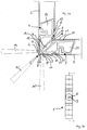
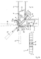
- Figures 1 and 2 show two possible embodiments of the corner connector 1 according to the invention for mitred hollow sections 2, 3 of windows, doors or the like.
- the two variants differ only in their mechanical fasteners, the will be explained in more detail below.
- the corner connector 1 at least a substantially in the direction of the miter joint 6 extending Distribution channel 7 for an injectable adhesive, wherein a Injection opening 8 is provided for the adhesive in the region of the miter joint 6 is.
- the injection opening 8 can be directly at the top of the miter joint. 6 be arranged or laterally thereof.
- the possible positions of the Injection opening 8 are designated by the reference numerals 8, 8 'and 8 ".
- the corner connector 1 is an extruded profile or of an extruded profile cut, wherein the distribution channel 7 transverse to the longitudinal center plane E-E of Corner connector 1 is continuous.
- the corner connector 1 together with the distribution channel 7 with little time and effort in one Production step are produced in the extrusion process.
- the Distribution channel 7 is at its two ends, each with a transverse bore 9, 10 in conjunction to initiate the adhesive in the distribution channel 7 to can and also from the distribution channel 7 to the mitres 11 inside Lead corner 12.
- the height of the corner connector 1 corresponds to the clear height of the hollow sections 2, 3, so the corner connector 1 is stably positioned in the ends of the hollow profiles 2, 3.
- an input channel thirteenth provided, which is in communication with the transverse bore 9.
- the input channel 13 is so broad outwardly formed that different positions for the injection opening 8, 8 ', 8 "for the adhesive at various points in Miter area are selectable. This possibility of different positioning of the injection openings 8, 8 ', 8 "is also through the various possible positions of the adhesive nozzle 13, 13 ', 13 ", which once shown by a solid line and twice by dashed lines, clarified.
- the input channel 13 is through the corner connector 1 and the deferred Hollow sections 2, 3 limited, so that the injected adhesive is forced further into the distribution channel 7 and the side channels 15, 16 to flow.
- the inlet channel 14 is conical or funnel-shaped and tapers towards the distribution channel 7.
- the input channel 14 is therefore not consistently formed as the distribution channel 7 and therefore must as well as the Transverse holes 9, 10 subsequently to the extruded corner connector. 1 be introduced.
- the input channel 14 is a stepped bore or lowered trained.
- each by the corner connector 1 and the deferred hollow sections 2, 3 is limited.
- the injected into the side channels 15, 16 adhesive connects the Corner connector 1 in the outer corner area with the mitres 11 of the hollow sections 2, Third
- a return channel 18 is also provided, which is extends over the height of the corner connector 1 and in the inner corner region 12 of the Corner connector 1 is arranged.
- the return channel 18 is as well as the input channel 15 by the corner connector 1 and the deferred hollow sections 2, 3 limited.
- the return channel 18 ensures that the incoming from the distribution channel 7 Adhesive is forwarded to the side channels 19, 20.
- the adhesive is therefore in the input channel 15, from there into the subsequent side channels 16, 17, the distribution channel 7 and the return channel and the adjoining side channels 19, 20 can be introduced, wherein the Adhesive but only by means of the adhesive nozzle 14 in the injection port 8, 8 ' or 8 "is injected.
- the outer edge 21 of the corner connector 1 is rounded, thereby ensuring in this area for even spreading of the adhesive.
- the corner connector is 1 with the hollow sections 2, 3 and non-positively in connection, these non-positive connection already made prior to injection of the adhesive becomes.
- the corner connector 1 with the hollow sections 2, 3 by connected mechanical fastening means.
- the corner connector 1 with the hollow sections 2, 3 pressed by inside protruding projections 22 of the hollow sections 2, 3 in recesses 23 of the Corner connector 1 engage or against the walls of the recesses 23 support.
- the hollow sections 2, 3 with the Corner connector 1 pinned, with a pin 24 or a rivet from the outside over the respective hollow profile 2, 3 in a corresponding recess 25 of the Corner connector 1 engages.
- corner connector 1 closed to its free leg ends Hollow chambers 26, 27, which ensure a high stability of the corner connector 1.
- the corner connector is made of aluminum or an aluminum alloy and thus from a material suitable for an extrusion process.
Landscapes
- Engineering & Computer Science (AREA)
- Civil Engineering (AREA)
- Structural Engineering (AREA)
- Joining Of Corner Units Of Frames Or Wings (AREA)
- Cleaning In General (AREA)
- Non-Disconnectible Joints And Screw-Threaded Joints (AREA)
- Standing Axle, Rod, Or Tube Structures Coupled By Welding, Adhesion, Or Deposition (AREA)
- Connector Housings Or Holding Contact Members (AREA)
Applications Claiming Priority (2)
| Application Number | Priority Date | Filing Date | Title |
|---|---|---|---|
| DE102004014595 | 2004-03-23 | ||
| DE102004014595A DE102004014595B3 (de) | 2004-03-23 | 2004-03-23 | Eckverbinder |
Publications (3)
| Publication Number | Publication Date |
|---|---|
| EP1580389A2 true EP1580389A2 (fr) | 2005-09-28 |
| EP1580389A3 EP1580389A3 (fr) | 2007-02-21 |
| EP1580389B1 EP1580389B1 (fr) | 2009-03-11 |
Family
ID=34854042
Family Applications (1)
| Application Number | Title | Priority Date | Filing Date |
|---|---|---|---|
| EP05005694A Expired - Lifetime EP1580389B1 (fr) | 2004-03-23 | 2005-03-16 | Joint d'angle pour un assemblage à onglet des profiles creux de fenêtres ou de portes |
Country Status (3)
| Country | Link |
|---|---|
| EP (1) | EP1580389B1 (fr) |
| AT (1) | ATE425340T1 (fr) |
| DE (2) | DE102004014595B3 (fr) |
Cited By (14)
| Publication number | Priority date | Publication date | Assignee | Title |
|---|---|---|---|---|
| GB2416561A (en) * | 2004-07-13 | 2006-02-01 | Rehau Ltd | Frame perpendicular joint |
| EP1911925A3 (fr) * | 2006-10-07 | 2011-11-23 | Norsk Hydro Asa | Cadre pour fenêtres, portes, éléments de façades ou analogues |
| DE202013103624U1 (de) | 2013-08-12 | 2014-11-14 | Raico Bautechnik Gmbh | Eckverbinder zur Verbindung auf Gehrung geschnittener Hohlprofile |
| EP2754840A3 (fr) * | 2013-01-11 | 2016-03-23 | HUECK GmbH & Co. KG | Raccord d'angle |
| CN107023248A (zh) * | 2017-06-17 | 2017-08-08 | 广州市福里事复合材料有限公司 | 一种门窗型材的组角方法 |
| DE102017104463B3 (de) | 2017-03-03 | 2018-08-23 | Nieke Composites Gmbh | Leichtbaukonstruktion und Verfahren |
| ES2759331A1 (es) * | 2018-11-07 | 2020-05-08 | Cano Manuel Blazquez | Escuadra de tetones |
| US20210010320A1 (en) * | 2019-07-12 | 2021-01-14 | Jeld-Wen, Inc. | Systems and methods for joining fenestration frame members |
| USD1009306S1 (en) | 2021-05-18 | 2023-12-26 | Jeld-Wen, Inc. | Corner key |
| USD1009307S1 (en) | 2021-05-18 | 2023-12-26 | Jeld-Wen, Inc. | Corner key |
| USD1009305S1 (en) | 2021-05-18 | 2023-12-26 | Jeld-Wen, Inc. | Corner key |
| USD1009308S1 (en) | 2021-05-18 | 2023-12-26 | Jeld-Wen, Inc. | Corner key |
| WO2024079075A1 (fr) * | 2022-10-12 | 2024-04-18 | REHAU Industries SE & Co. KG | Procédé de fabrication d'un joint d'angle, élément de liaison pour un joint d'angle et joint d'angle |
| US20250172036A1 (en) * | 2023-11-28 | 2025-05-29 | Mi Windows And Doors, Llc | Frame corner key |
Families Citing this family (5)
| Publication number | Priority date | Publication date | Assignee | Title |
|---|---|---|---|---|
| DE102006050572B4 (de) * | 2006-07-08 | 2017-11-23 | Hueck Gmbh & Co. Kg | Profilrahmen |
| DE102011107060B4 (de) * | 2011-07-11 | 2024-07-18 | Hörmann Kg Brandis | Verfahren zum Verbinden von Hohlprofilstäben, Eckverbinder sowie Tür-/Tüblatt-/Verglasungsrahmen |
| DE102011118211B4 (de) * | 2011-11-11 | 2024-11-21 | Heroal - Johann Henkenjohann Gmbh & Co. Kg | Eckverbindung eines Rahmens mit einem mit einem Klebstoff ausgefüllten Innenraum |
| DE102014112092A1 (de) * | 2014-08-25 | 2016-02-25 | SCHÜCO International KG | Tür, Fenster oder Fassadenelement mit einem Eckverbinder |
| GB202307644D0 (en) * | 2023-05-22 | 2023-07-05 | Aanico Uk Ltd | A sealed mitre joint and associated method of manufacture |
Citations (1)
| Publication number | Priority date | Publication date | Assignee | Title |
|---|---|---|---|---|
| EP0810344B1 (fr) | 1993-02-10 | 2002-07-17 | SCHÜCO International KG | Equerre et profilés creux associés, coupés en onglet pour encadrement de fenêtres, portes ou façades |
Family Cites Families (7)
| Publication number | Priority date | Publication date | Assignee | Title |
|---|---|---|---|---|
| DE3015140A1 (de) * | 1980-04-19 | 1981-10-29 | Gebrüder Uhl GmbH & Co KG, 7981 Vogt | Stabilisierungs- undausrichtelement fuer aus profilteilen zusammengesetzte rahmen von fenstern, tueren o.dgl. |
| DE4305377C2 (de) * | 1993-02-22 | 2000-06-15 | Hueck Eduard Gmbh Co Kg | Gehrungseckverbindung |
| DE19633783C1 (de) * | 1996-08-22 | 1998-06-04 | Hueck Eduard Gmbh Co Kg | Gehrungseckverbindung |
| FR2759111B1 (fr) * | 1997-02-06 | 1999-10-22 | Alcan France | Dispositif pour l'assemblage de profiles d'un chassis de porte, fenetre ou analogue |
| US5921037A (en) * | 1997-03-25 | 1999-07-13 | Pella Corporation | Fenestration product with unitary frame members and method of manufacture |
| DE10118791B4 (de) * | 2001-04-18 | 2012-06-21 | Adrian Kosak | Verbindungselement |
| DE20217301U1 (de) * | 2002-11-09 | 2004-03-18 | SCHÜCO International KG | Eckverbinder für auf Gehrung geschnittene Hohlprofile eines Rahmens |
-
2004
- 2004-03-23 DE DE102004014595A patent/DE102004014595B3/de not_active Expired - Fee Related
-
2005
- 2005-03-16 AT AT05005694T patent/ATE425340T1/de active
- 2005-03-16 EP EP05005694A patent/EP1580389B1/fr not_active Expired - Lifetime
- 2005-03-16 DE DE502005006778T patent/DE502005006778D1/de not_active Expired - Lifetime
Patent Citations (1)
| Publication number | Priority date | Publication date | Assignee | Title |
|---|---|---|---|---|
| EP0810344B1 (fr) | 1993-02-10 | 2002-07-17 | SCHÜCO International KG | Equerre et profilés creux associés, coupés en onglet pour encadrement de fenêtres, portes ou façades |
Cited By (18)
| Publication number | Priority date | Publication date | Assignee | Title |
|---|---|---|---|---|
| GB2416561A (en) * | 2004-07-13 | 2006-02-01 | Rehau Ltd | Frame perpendicular joint |
| GB2416561B (en) * | 2004-07-13 | 2008-02-27 | Rehau Ltd | Structural Frame |
| EP1911925A3 (fr) * | 2006-10-07 | 2011-11-23 | Norsk Hydro Asa | Cadre pour fenêtres, portes, éléments de façades ou analogues |
| EP2754840A3 (fr) * | 2013-01-11 | 2016-03-23 | HUECK GmbH & Co. KG | Raccord d'angle |
| DE202013103624U1 (de) | 2013-08-12 | 2014-11-14 | Raico Bautechnik Gmbh | Eckverbinder zur Verbindung auf Gehrung geschnittener Hohlprofile |
| DE102017104463B3 (de) | 2017-03-03 | 2018-08-23 | Nieke Composites Gmbh | Leichtbaukonstruktion und Verfahren |
| CN107023248A (zh) * | 2017-06-17 | 2017-08-08 | 广州市福里事复合材料有限公司 | 一种门窗型材的组角方法 |
| CN107023248B (zh) * | 2017-06-17 | 2019-04-05 | 广州市福里事复合材料有限公司 | 一种门窗型材的组角方法 |
| ES2759331A1 (es) * | 2018-11-07 | 2020-05-08 | Cano Manuel Blazquez | Escuadra de tetones |
| WO2020094894A1 (fr) * | 2018-11-07 | 2020-05-14 | Blazquez Cano Manuel | Équerre à tétons |
| US20210010320A1 (en) * | 2019-07-12 | 2021-01-14 | Jeld-Wen, Inc. | Systems and methods for joining fenestration frame members |
| US11585149B2 (en) * | 2019-07-12 | 2023-02-21 | Jeld-Wen, Inc. | Systems and methods for joining fenestration frame members |
| USD1009306S1 (en) | 2021-05-18 | 2023-12-26 | Jeld-Wen, Inc. | Corner key |
| USD1009307S1 (en) | 2021-05-18 | 2023-12-26 | Jeld-Wen, Inc. | Corner key |
| USD1009305S1 (en) | 2021-05-18 | 2023-12-26 | Jeld-Wen, Inc. | Corner key |
| USD1009308S1 (en) | 2021-05-18 | 2023-12-26 | Jeld-Wen, Inc. | Corner key |
| WO2024079075A1 (fr) * | 2022-10-12 | 2024-04-18 | REHAU Industries SE & Co. KG | Procédé de fabrication d'un joint d'angle, élément de liaison pour un joint d'angle et joint d'angle |
| US20250172036A1 (en) * | 2023-11-28 | 2025-05-29 | Mi Windows And Doors, Llc | Frame corner key |
Also Published As
| Publication number | Publication date |
|---|---|
| EP1580389A3 (fr) | 2007-02-21 |
| DE502005006778D1 (de) | 2009-04-23 |
| ATE425340T1 (de) | 2009-03-15 |
| EP1580389B1 (fr) | 2009-03-11 |
| DE102004014595B3 (de) | 2005-12-22 |
Similar Documents
| Publication | Publication Date | Title |
|---|---|---|
| DE102004014595B3 (de) | Eckverbinder | |
| EP0810344A2 (fr) | Equerre et profilés creux associés, coupés en onglet pour encadrement de fenêtres, portes ou façades | |
| EP2154323A2 (fr) | Joint d'angle pour un assemblage à onglet de profiles creux | |
| EP3135849B1 (fr) | Liaison bout-a-bout pour injection de colle et combinaison de raccord et cadre | |
| WO2005019588A1 (fr) | Raccord d'angle et procede de fabrication associe | |
| DE3236719A1 (de) | Klemmverbinder fuer profilleisten | |
| EP2090725A1 (fr) | Âme destinée à relier les deux moitiés cylindriques d'une serrure à double cylindre variable en longueur | |
| EP3124734A1 (fr) | Systeme de liaison destine a relier un jambage a un profil de cadre d'une fenetre ou d'une porte en matiere plastique | |
| DE10118791A1 (de) | Verbindungselement | |
| DE202016002633U1 (de) | Spreizender Eckverbinder | |
| EP1587396B1 (fr) | Procede de production d'un corps de meuble | |
| DE19539862C2 (de) | Eckverbindung für Hohlprofilstäbe zur Bildung von Rahmenteilen | |
| DE9116873U1 (de) | Verbindungsvorrichtung für eine Sprossenkreuzkonstruktion | |
| DE20114224U1 (de) | Vorrichtung zur Verbindung von Hohlprofilen zu Rahmenteilen | |
| EP2933507A1 (fr) | Système de joint en bout, encadrement de fenêtre/de porte ou encadrement de vantail de porte/de fenêtre et élément de profilé d'encadrement | |
| DE102004014598B4 (de) | Stoßverbinder zur Verbindung von Profilen | |
| DE3924547A1 (de) | Eckverbinder fuer tuer- oder fensterrahmen | |
| EP0835978B1 (fr) | Cadre pour fenêtres, portes, façades ou des choses pareilles | |
| DE19900957C2 (de) | Eckverbinder für Hohlprofilrahmen von Fenstern und Türen | |
| EP0371237B1 (fr) | Jeu de pièces détachées pour un châssis de porte | |
| EP0681083B1 (fr) | Raccord rectiligne en matière plastique pour profilés intercalaires creux et pour profilés creux de croisillon d'un vitrage multiple isolant | |
| DE102012218887B4 (de) | Schließstück für ein Fenster, eine Tür oder dergleichen | |
| EP2128372A2 (fr) | Fenêtre ou porte en matière plastique et son procédé de fabrication | |
| DE19940574C1 (de) | Anordnung zur Bildung einer Kreuzverbindung zwischen einem Längspfosten und einem Querpfosten bei einem Fenster oder einer Türe aus Kunststoff oder Leichtmetall | |
| EP0291973B1 (fr) | Pièce de jonction de deux barres profilées aboutissant angulairement pour cadres de fenêtre ou porte |
Legal Events
| Date | Code | Title | Description |
|---|---|---|---|
| PUAI | Public reference made under article 153(3) epc to a published international application that has entered the european phase |
Free format text: ORIGINAL CODE: 0009012 |
|
| AK | Designated contracting states |
Kind code of ref document: A2 Designated state(s): AT BE BG CH CY CZ DE DK EE ES FI FR GB GR HU IE IS IT LI LT LU MC NL PL PT RO SE SI SK TR |
|
| AX | Request for extension of the european patent |
Extension state: AL BA HR LV MK YU |
|
| RAP1 | Party data changed (applicant data changed or rights of an application transferred) |
Owner name: HERMANN GUTMANN WERKE AG |
|
| PUAL | Search report despatched |
Free format text: ORIGINAL CODE: 0009013 |
|
| AK | Designated contracting states |
Kind code of ref document: A3 Designated state(s): AT BE BG CH CY CZ DE DK EE ES FI FR GB GR HU IE IS IT LI LT LU MC NL PL PT RO SE SI SK TR |
|
| AX | Request for extension of the european patent |
Extension state: AL BA HR LV MK YU |
|
| 17P | Request for examination filed |
Effective date: 20070813 |
|
| AKX | Designation fees paid |
Designated state(s): AT CH DE LI |
|
| 17Q | First examination report despatched |
Effective date: 20080724 |
|
| GRAP | Despatch of communication of intention to grant a patent |
Free format text: ORIGINAL CODE: EPIDOSNIGR1 |
|
| RTI1 | Title (correction) |
Free format text: CORNER CONNECTOR FOR MITRE JOINTS OF HOLLOW WINDOW OR DOOR PROFILES |
|
| GRAS | Grant fee paid |
Free format text: ORIGINAL CODE: EPIDOSNIGR3 |
|
| GRAA | (expected) grant |
Free format text: ORIGINAL CODE: 0009210 |
|
| AK | Designated contracting states |
Kind code of ref document: B1 Designated state(s): AT CH DE LI |
|
| REG | Reference to a national code |
Ref country code: CH Ref legal event code: EP |
|
| REF | Corresponds to: |
Ref document number: 502005006778 Country of ref document: DE Date of ref document: 20090423 Kind code of ref document: P |
|
| REG | Reference to a national code |
Ref country code: CH Ref legal event code: NV Representative=s name: PATENTANWAELTE SCHAAD, BALASS, MENZL & PARTNER AG |
|
| PLBE | No opposition filed within time limit |
Free format text: ORIGINAL CODE: 0009261 |
|
| STAA | Information on the status of an ep patent application or granted ep patent |
Free format text: STATUS: NO OPPOSITION FILED WITHIN TIME LIMIT |
|
| 26N | No opposition filed |
Effective date: 20091214 |
|
| REG | Reference to a national code |
Ref country code: CH Ref legal event code: PFA Owner name: GUTMANN AG Free format text: HERMANN GUTMANN WERKE AG#NUERNBERGER STRASSE 57-81#91781 WEISSENBURG (DE) -TRANSFER TO- GUTMANN AG#NUERNBERGER STRASSE 57#91781 WEISSENBURG (DE) |
|
| REG | Reference to a national code |
Ref country code: DE Ref legal event code: R081 Ref document number: 502005006778 Country of ref document: DE Owner name: GUTMANN AG, DE Free format text: FORMER OWNER: HERMANN GUTMANN WERKE AG, 91781 WEISSENBURG, DE Effective date: 20110311 |
|
| PGFP | Annual fee paid to national office [announced via postgrant information from national office to epo] |
Ref country code: CH Payment date: 20120323 Year of fee payment: 8 |
|
| PGFP | Annual fee paid to national office [announced via postgrant information from national office to epo] |
Ref country code: AT Payment date: 20120321 Year of fee payment: 8 |
|
| REG | Reference to a national code |
Ref country code: CH Ref legal event code: PL |
|
| REG | Reference to a national code |
Ref country code: AT Ref legal event code: MM01 Ref document number: 425340 Country of ref document: AT Kind code of ref document: T Effective date: 20130316 |
|
| PG25 | Lapsed in a contracting state [announced via postgrant information from national office to epo] |
Ref country code: LI Free format text: LAPSE BECAUSE OF NON-PAYMENT OF DUE FEES Effective date: 20130331 Ref country code: AT Free format text: LAPSE BECAUSE OF NON-PAYMENT OF DUE FEES Effective date: 20130316 Ref country code: CH Free format text: LAPSE BECAUSE OF NON-PAYMENT OF DUE FEES Effective date: 20130331 |
|
| PGFP | Annual fee paid to national office [announced via postgrant information from national office to epo] |
Ref country code: DE Payment date: 20221214 Year of fee payment: 19 |
|
| P01 | Opt-out of the competence of the unified patent court (upc) registered |
Effective date: 20230530 |
|
| REG | Reference to a national code |
Ref country code: DE Ref legal event code: R119 Ref document number: 502005006778 Country of ref document: DE |
|
| PG25 | Lapsed in a contracting state [announced via postgrant information from national office to epo] |
Ref country code: DE Free format text: LAPSE BECAUSE OF NON-PAYMENT OF DUE FEES Effective date: 20241001 |
|
| PG25 | Lapsed in a contracting state [announced via postgrant information from national office to epo] |
Ref country code: DE Free format text: LAPSE BECAUSE OF NON-PAYMENT OF DUE FEES Effective date: 20241001 |