EP1580441A2 - Méthode de contrôle des vibrations induites dans un vérin hydraulique lors d'un arrêt brutal - Google Patents
Méthode de contrôle des vibrations induites dans un vérin hydraulique lors d'un arrêt brutal Download PDFInfo
- Publication number
- EP1580441A2 EP1580441A2 EP04017918A EP04017918A EP1580441A2 EP 1580441 A2 EP1580441 A2 EP 1580441A2 EP 04017918 A EP04017918 A EP 04017918A EP 04017918 A EP04017918 A EP 04017918A EP 1580441 A2 EP1580441 A2 EP 1580441A2
- Authority
- EP
- European Patent Office
- Prior art keywords
- hydraulic cylinder
- hydraulic
- hydraulic fluid
- sudden stop
- chamber
- Prior art date
- Legal status (The legal status is an assumption and is not a legal conclusion. Google has not performed a legal analysis and makes no representation as to the accuracy of the status listed.)
- Granted
Links
Images


Classifications
-
- A—HUMAN NECESSITIES
- A47—FURNITURE; DOMESTIC ARTICLES OR APPLIANCES; COFFEE MILLS; SPICE MILLS; SUCTION CLEANERS IN GENERAL
- A47G—HOUSEHOLD OR TABLE EQUIPMENT
- A47G25/00—Household implements used in connection with wearing apparel; Dress, hat or umbrella holders
- A47G25/80—Devices for putting-on or removing boots or shoes, e.g. boot-hooks, boot-jacks
-
- F—MECHANICAL ENGINEERING; LIGHTING; HEATING; WEAPONS; BLASTING
- F15—FLUID-PRESSURE ACTUATORS; HYDRAULICS OR PNEUMATICS IN GENERAL
- F15B—SYSTEMS ACTING BY MEANS OF FLUIDS IN GENERAL; FLUID-PRESSURE ACTUATORS, e.g. SERVOMOTORS; DETAILS OF FLUID-PRESSURE SYSTEMS, NOT OTHERWISE PROVIDED FOR
- F15B21/00—Common features of fluid actuator systems; Fluid-pressure actuator systems or details thereof, not covered by any other group of this subclass
- F15B21/08—Servomotor systems incorporating electrically operated control means
- F15B21/087—Control strategy, e.g. with block diagram
-
- E—FIXED CONSTRUCTIONS
- E02—HYDRAULIC ENGINEERING; FOUNDATIONS; SOIL SHIFTING
- E02F—DREDGING; SOIL-SHIFTING
- E02F9/00—Component parts of dredgers or soil-shifting machines, not restricted to one of the kinds covered by groups E02F3/00 - E02F7/00
- E02F9/20—Drives; Control devices
- E02F9/22—Hydraulic or pneumatic drives
- E02F9/2203—Arrangements for controlling the attitude of actuators, e.g. speed, floating function
- E02F9/2207—Arrangements for controlling the attitude of actuators, e.g. speed, floating function for reducing or compensating oscillations
-
- F—MECHANICAL ENGINEERING; LIGHTING; HEATING; WEAPONS; BLASTING
- F15—FLUID-PRESSURE ACTUATORS; HYDRAULICS OR PNEUMATICS IN GENERAL
- F15B—SYSTEMS ACTING BY MEANS OF FLUIDS IN GENERAL; FLUID-PRESSURE ACTUATORS, e.g. SERVOMOTORS; DETAILS OF FLUID-PRESSURE SYSTEMS, NOT OTHERWISE PROVIDED FOR
- F15B11/00—Servomotor systems without provision for follow-up action; Circuits therefor
- F15B11/02—Systems essentially incorporating special features for controlling the speed or actuating force of an output member
- F15B11/04—Systems essentially incorporating special features for controlling the speed or actuating force of an output member for controlling the speed
- F15B11/0406—Systems essentially incorporating special features for controlling the speed or actuating force of an output member for controlling the speed during starting or stopping
-
- F—MECHANICAL ENGINEERING; LIGHTING; HEATING; WEAPONS; BLASTING
- F15—FLUID-PRESSURE ACTUATORS; HYDRAULICS OR PNEUMATICS IN GENERAL
- F15B—SYSTEMS ACTING BY MEANS OF FLUIDS IN GENERAL; FLUID-PRESSURE ACTUATORS, e.g. SERVOMOTORS; DETAILS OF FLUID-PRESSURE SYSTEMS, NOT OTHERWISE PROVIDED FOR
- F15B2211/00—Circuits for servomotor systems
- F15B2211/20—Fluid pressure source, e.g. accumulator or variable axial piston pump
- F15B2211/205—Systems with pumps
- F15B2211/2053—Type of pump
- F15B2211/20546—Type of pump variable capacity
- F15B2211/20553—Type of pump variable capacity with pilot circuit, e.g. for controlling a swash plate
-
- F—MECHANICAL ENGINEERING; LIGHTING; HEATING; WEAPONS; BLASTING
- F15—FLUID-PRESSURE ACTUATORS; HYDRAULICS OR PNEUMATICS IN GENERAL
- F15B—SYSTEMS ACTING BY MEANS OF FLUIDS IN GENERAL; FLUID-PRESSURE ACTUATORS, e.g. SERVOMOTORS; DETAILS OF FLUID-PRESSURE SYSTEMS, NOT OTHERWISE PROVIDED FOR
- F15B2211/00—Circuits for servomotor systems
- F15B2211/20—Fluid pressure source, e.g. accumulator or variable axial piston pump
- F15B2211/205—Systems with pumps
- F15B2211/20576—Systems with pumps with multiple pumps
-
- F—MECHANICAL ENGINEERING; LIGHTING; HEATING; WEAPONS; BLASTING
- F15—FLUID-PRESSURE ACTUATORS; HYDRAULICS OR PNEUMATICS IN GENERAL
- F15B—SYSTEMS ACTING BY MEANS OF FLUIDS IN GENERAL; FLUID-PRESSURE ACTUATORS, e.g. SERVOMOTORS; DETAILS OF FLUID-PRESSURE SYSTEMS, NOT OTHERWISE PROVIDED FOR
- F15B2211/00—Circuits for servomotor systems
- F15B2211/20—Fluid pressure source, e.g. accumulator or variable axial piston pump
- F15B2211/255—Flow control functions
-
- F—MECHANICAL ENGINEERING; LIGHTING; HEATING; WEAPONS; BLASTING
- F15—FLUID-PRESSURE ACTUATORS; HYDRAULICS OR PNEUMATICS IN GENERAL
- F15B—SYSTEMS ACTING BY MEANS OF FLUIDS IN GENERAL; FLUID-PRESSURE ACTUATORS, e.g. SERVOMOTORS; DETAILS OF FLUID-PRESSURE SYSTEMS, NOT OTHERWISE PROVIDED FOR
- F15B2211/00—Circuits for servomotor systems
- F15B2211/30—Directional control
- F15B2211/305—Directional control characterised by the type of valves
- F15B2211/30525—Directional control valves, e.g. 4/3-directional control valve
-
- F—MECHANICAL ENGINEERING; LIGHTING; HEATING; WEAPONS; BLASTING
- F15—FLUID-PRESSURE ACTUATORS; HYDRAULICS OR PNEUMATICS IN GENERAL
- F15B—SYSTEMS ACTING BY MEANS OF FLUIDS IN GENERAL; FLUID-PRESSURE ACTUATORS, e.g. SERVOMOTORS; DETAILS OF FLUID-PRESSURE SYSTEMS, NOT OTHERWISE PROVIDED FOR
- F15B2211/00—Circuits for servomotor systems
- F15B2211/30—Directional control
- F15B2211/32—Directional control characterised by the type of actuation
- F15B2211/329—Directional control characterised by the type of actuation actuated by fluid pressure
-
- F—MECHANICAL ENGINEERING; LIGHTING; HEATING; WEAPONS; BLASTING
- F15—FLUID-PRESSURE ACTUATORS; HYDRAULICS OR PNEUMATICS IN GENERAL
- F15B—SYSTEMS ACTING BY MEANS OF FLUIDS IN GENERAL; FLUID-PRESSURE ACTUATORS, e.g. SERVOMOTORS; DETAILS OF FLUID-PRESSURE SYSTEMS, NOT OTHERWISE PROVIDED FOR
- F15B2211/00—Circuits for servomotor systems
- F15B2211/60—Circuit components or control therefor
- F15B2211/63—Electronic controllers
- F15B2211/6303—Electronic controllers using input signals
- F15B2211/6306—Electronic controllers using input signals representing a pressure
- F15B2211/6313—Electronic controllers using input signals representing a pressure the pressure being a load pressure
-
- F—MECHANICAL ENGINEERING; LIGHTING; HEATING; WEAPONS; BLASTING
- F15—FLUID-PRESSURE ACTUATORS; HYDRAULICS OR PNEUMATICS IN GENERAL
- F15B—SYSTEMS ACTING BY MEANS OF FLUIDS IN GENERAL; FLUID-PRESSURE ACTUATORS, e.g. SERVOMOTORS; DETAILS OF FLUID-PRESSURE SYSTEMS, NOT OTHERWISE PROVIDED FOR
- F15B2211/00—Circuits for servomotor systems
- F15B2211/70—Output members, e.g. hydraulic motors or cylinders or control therefor
- F15B2211/705—Output members, e.g. hydraulic motors or cylinders or control therefor characterised by the type of output members or actuators
- F15B2211/7051—Linear output members
- F15B2211/7053—Double-acting output members
-
- F—MECHANICAL ENGINEERING; LIGHTING; HEATING; WEAPONS; BLASTING
- F15—FLUID-PRESSURE ACTUATORS; HYDRAULICS OR PNEUMATICS IN GENERAL
- F15B—SYSTEMS ACTING BY MEANS OF FLUIDS IN GENERAL; FLUID-PRESSURE ACTUATORS, e.g. SERVOMOTORS; DETAILS OF FLUID-PRESSURE SYSTEMS, NOT OTHERWISE PROVIDED FOR
- F15B2211/00—Circuits for servomotor systems
- F15B2211/80—Other types of control related to particular problems or conditions
- F15B2211/86—Control during or prevention of abnormal conditions
- F15B2211/8616—Control during or prevention of abnormal conditions the abnormal condition being noise or vibration
Definitions
- the present invention relates in general to a hydraulic cylinder, and more particularly, to a hydraulic cylinder suspension method for actively controlling vibration that is generated when a hydraulic cylinder such as a boom cylinder in a construction vehicle stops running all of a sudden.
- a construction vehicle including an excavator is provided with various working equipments such as a boom, arm, and bucket, and is driven by a hydraulic cylinder that is operated by hydraulic fluid from a hydraulic pump.
- a control valve is installed between the hydraulic pump and the hydraulic cylinder. It is the control valve that controls the hydraulic fluid from the hydraulic pump and supplies it to every hydraulic cylinder. More specifically, to drive the construction vehicle, a driver operates an operation lever, and then a control device controls the control valve, whereby hydraulic pressure, direction and flow of the hydraulic fluid supplied to the hydraulic cylinders are controlled.
- the working equipment is usually heavy and massive capable of withstanding overload and rough work environment. Because of its heavy weight, inertia of the working equipment is also large. Thus, when the working equipment is in operation or stops running, it vibrates a lot due to the large inertia. In case of driving a construction vehicle, although an experienced driver can operate the operation lever with great delicacy and skill to move the working equipment gently, a beginner often finds difficulty in handling the operation lever, especially for starting and finishing the operation of the lever because of shock-induced vibration generated by inertia of the working equipment.
- One of generally used techniques for relieving shocks generated from a sudden operation of the working equipment is to use a pressure sensor that senses whether the operation lever starts operating suddenly and if so, a controller controls the control valve by changing an operation signal from the operation lever to proper signal for preventing vibration.
- the above technique only attempts to control the control valve to prevent the sudden operation of the working equipment by changing the operation signal from the operation lever, and it does not provide a fundamental solution for the actual vibration that is generated when the hydraulic cylinder of the working equipment gets a shock.
- an object of the present invention to provide a hydraulic cylinder suspension method for actively controlling shock-induced vibration generated when a hydraulic cylinder of a construction vehicle suddenly stops working, whereby work efficiency using the working equipment can be improved and driver fatigue can be reduced.
- a hydraulic cylinder suspension method for use in a hydraulic drive system comprised of a hydraulic cylinder driving a working equipment and having a large chamber and a small chamber to which hydraulic fluid from a hydraulic pump is supplied, a control valve allowing the hydraulic fluid in the hydraulic pumps to be supplied to the hydraulic cylinder and returning the hydraulic fluid from the hydraulic cylinder to a tank, an operation lever for generating an operation signal to drive the working equipment, a controller changing the operational signal and generating a control signal for controlling the control valve, a valve drive unit controlling the control valve according to the control signal from the controller, and a pressure detection means mounted on the large chamber of the hydraulic cylinder and detecting operational pressure on the large chamber, the method comprising the steps of: receiving the operation signal of the operation lever and determining whether the hydraulic cylinder makes a sudden stop; receiving a pressure signal from the pressure detection means mounted on the large chamber of the hydraulic cylinder; if the hydraulic cylinder makes the sudden stop, determining whether the hydraulic cylinder is being extended or compressed; and if the hydraulic
- to optimally control vibration supply time of hydraulic fluid to the large chamber and the small chamber is within a range of 1/12 to 1/4 of a period of the pressure signal starting from a maximum/minimum point where the pressure signal reaches for the first time, and when the hydraulic fluid is supplied to the large and small chambers, opening are of the control valve is within a range of 1/4 to 3/4 of a maximum opening.
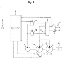
- Fig. 1 is a schematic diagram of a hydraulic system to which a hydraulic cylinder suspension method according to one embodiment of the present invention is applied.
- the hydraulic system to which a hydraulic cylinder suspension method is applied, includes hydraulic pumps 8a, 8b driven by an engine 10; a boom cylinder 6 for driving a boom (not shown), one of working equipments, by using hydraulic fluid from the hydraulic pumps 8a, 8b; a control valve 4 for supplying hydraulic fluid in the hydraulic pumps 8a, 8b to the boom cylinder 6; an operation lever 2 for generating an operation signal for driving an working equipment (not shown); a controller 1 for changing the operational signal to a control signal; and valve drivers 3a and 3b for controlling the control valve 4 according to the control signal from the controller 1.
- a generally known hydraulic cylinder is used as the boom cylinder 6.
- the boom cylinder 6 is divided into a large chamber 6a and a small chamber 6b.
- the control valve 4 allows the hydraulic fluid from the hydraulic pumps 8a, 8b to be supplied to the large chamber 6a, while the hydraulic fluid in the small chamber 6b flows back to a tank 11.
- the control valve 4 allows the hydraulic fluid from the hydraulic pumps 8a, 8b to be supplied to the small chamber 6b, while the hydraulic fluid in the large chamber 6a flows back to the tank 11.
- a pressure detection means 5 is mounted on the large chamber 6a of the boom cylinder 6. The pressure detection means 5 detects pressure operating on the large chamber 6a of the boom cylinder 6, and a detected pressure signal is transferred to the controller 1.
- valve drivers 3a and 3b are connected to a pilot pump 7 and create a pilot pressure, according to the control signal from the controller 1.
- pilot pressure is provided to the control valve 4 to be used in controlling the operation of the control valve 4.
- Reference numerals 9a and 9ba in Fig. 1 denote pump flow control means.
- the operation lever 2 is a device generating an operation signal for driving working equipment (not shown).
- the operation signal of the operation lever 2 is inputted to the controller 1 and is changed, by the controller 1, to the control signal for driving the valve drivers 3a and 3b.
- the controller 1 outputs the control signal for operating the valve drivers 3a and 3b according to the inputted operational signal from the operation lever 2, thereby controlling the operation of the control valve 4 and causing the boom cylinder 6 to run.
- the controller 1 determines, on the basis of the operation signal from the operation lever 2, whether the boom cylinder 6 has been suddenly stopped. If it turns out that the boom cylinder 6 made a sudden stop by the sudden operation of the operation lever 2, the controller 1 actively controls the vibration generated in the boom cylinder 6. As described above, a pressure signal, detected by the pressure detection means 5, indicating pressure state of the large chamber 6a of the boom cylinder 6 is also sent to the controller 1, so the controller 1 is capable of performing active suspension work in response to the pressure state in the boom cylinder.
- the controller 1 determines whether the boom cylinder 6 made the sudden stop while a boom (not shown) was ascending or while a boom (not shown) was descending, and drives the valve drivers 3a and 3b appropriate for each case, thereby controlling the vibration.
- the controller 1 allows the hydraulic fluid to be supplied to the large chamber 6a for a certain amount of time starting from a point where the pressure signal has reached a minimum for the first time, and also allows the hydraulic fluid in the small chamber 6a to flow back to the tank 11. Moreover, the controller 1 allows the hydraulic fluid to be supplied to the small chamber 6b for a certain amount of time starting from a point where the pressure signal has reached a maximum for the first time, and also allows the hydraulic fluid in the large chamber 6a to flow back to the tank 11. In this manner, the vibration generated in the boom cylinder 6 is actively controlled.
- the controller 1 allows the hydraulic fluid to be supplied to the small chamber 6b for a certain amount of time starting from a point where the pressure signal has reached a maximum for the first time, and also allows the hydraulic fluid in the large chamber 6b to flow back to the tank 11.
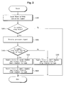
- Fig. 2 is a flow chart describing a control flow of the hydraulic cylinder suspension method according to one embodiment of the present invention
- Fig. 3 graphically illustrates a relation between hydraulic fluid supply time and boom ascending control input when the boom cylinder makes a sudden stop, in relation to the hydraulic cylinder suspension method according to one embodiment of the present invention
- Fig. 4 graphically illustrates a relation between hydraulic fluid supply time and boom descending control input when the boom cylinder makes a sudden stop, in relation to the hydraulic cylinder suspension method according to one embodiment of the present invention.
- the hydraulic cylinder suspension method largely includes sudden stop determination step (S100, S200); pressure signal receiving step (S300); operational direction determination step (S400); and hydraulic fluid supply step (S500, S600, and S700).
- the hydraulic fluid supply step is associated with two cases: first, the boom cylinder 6 makes the sudden stop while it was being extended (S500, S600), and second, the boom cylinder 6 makes the sudden stop while it was being compressed (S700).
- the controller receives the operation signal from the operation lever 2 and determines whether the boom cylinder 6 made a sudden stop. If the operation signal of the operation lever 2 corresponds to a sudden operation signal, the controller 1 determines that the boom cylinder 6 has suddenly stopped and thus, performs the following steps for actively controlling the vibration generated in the boom cylinder 6.
- the controller 1 receives the pressure signal from the pressure detection means 5 mounted on the large chamber 6a of the boom cylinder 6.
- the controller 1 actively controls the vibration, in response to a pressure change generated in the large chamber 6a or based on the received pressure signal.
- the controller 1 determines the movement direction of the boom cylinder 6 when the boom cylinder 6 made a sudden stop, so this is actually a very important step. That is, the controller 1 selects a chamber to which hydraulic fluid should be supplied in order to offset the shock-induced vibration generated by the sudden stop of the boom cylinder 6, according to whether the boom cylinder 6 has been suddenly stopped while the boom was ascending (i.e. while the boom cylinder 6 was being extended) or the boom cylinder has been suddenly stopped while the boom was descending (i.e. while the boom cylinder 6 was being compressed).
- the hydraulic fluid supply step (S500, S600, and S700) is associated with two cases: first, the boom cylinder 6 makes the sudden stop while the boom was being extended (S500, S600), and second, the boom cylinder 6 makes the sudden stop while it was being compressed (S700).
- 'T' denotes a period of fluctuation of the pressure signal.
- the controller 1 allows the hydraulic fluid to be supplied to the large chamber 6a for a certain amount of time t2 starting from a point t1 where the pressure signal has reached a minimum for the first time, and also allows the hydraulic fluid in the small chamber 6a to flow back to the tank 11. Afterwards, the controller 1 allows the hydraulic fluid to be supplied to the small chamber 6b for a certain amount of time t2 starting from a point where the pressure signal has reached a maximum for the first time, and also allows the hydraulic fluid in the large chamber 6a to flow back to the tank 11. In this manner, the vibration generated in the boom cylinder 6 is actively controlled.
- the controller 1 allows the hydraulic fluid to be supplied to the small chamber 6b (S700). That is, the controller 1 allows the hydraulic fluid to be supplied to the small chamber 6b for a certain amount of time t2 starting from a point where the pressure signal has reached a maximum for the first time, and also allows the hydraulic fluid in the large chamber 6b to flow back to the tank 11, thereby actively controlling the vibration generated in the boom cylinder 6.
- the supply time of the hydraulic fluid to the large and small chambers 6a and 6b falls within the range of 1/12 to 1/4 of the period of the pressure signal starting from the maximum/minimum point where the pressure signal reached for the first time.
- the range is obtained after carrying out experimental researches on the boom cylinder and vibration characteristics of the system, by which the vibration can be optimally controlled.
- control valve 4 when hydraulic fluid is supplied to the large and small chambers 6a and 6b, the opening area of control valve 4 is preferably within a range of 1/4 to 3/4 of its maximum opening. Again, this range is obtained from experiments to find a value at which the vibration of the boom cylinder 6 is optimally controlled.
- the shock-induced vibration caused by the sudden stop of the hydraulic cylinder in a construction vehicle can be actively controlled and as a result of this, endurance of vehicle is improved, work efficiency using working equipment is improved, and fatigue to the driver is much reduced.
Landscapes
- Engineering & Computer Science (AREA)
- General Engineering & Computer Science (AREA)
- Physics & Mathematics (AREA)
- Fluid Mechanics (AREA)
- Mechanical Engineering (AREA)
- Civil Engineering (AREA)
- Mining & Mineral Resources (AREA)
- Structural Engineering (AREA)
- Chemical & Material Sciences (AREA)
- Analytical Chemistry (AREA)
- Operation Control Of Excavators (AREA)
- Fluid-Pressure Circuits (AREA)
- Vehicle Body Suspensions (AREA)
Applications Claiming Priority (2)
| Application Number | Priority Date | Filing Date | Title |
|---|---|---|---|
| KR2004019258 | 2004-03-22 | ||
| KR1020040019258A KR100559296B1 (ko) | 2004-03-22 | 2004-03-22 | 유압실린더의 진동 제어방법 |
Publications (3)
| Publication Number | Publication Date |
|---|---|
| EP1580441A2 true EP1580441A2 (fr) | 2005-09-28 |
| EP1580441A3 EP1580441A3 (fr) | 2005-10-05 |
| EP1580441B1 EP1580441B1 (fr) | 2007-04-04 |
Family
ID=34858859
Family Applications (1)
| Application Number | Title | Priority Date | Filing Date |
|---|---|---|---|
| EP04017918A Expired - Lifetime EP1580441B1 (fr) | 2004-03-22 | 2004-07-29 | Méthode de contrôle des vibrations induites dans un vérin hydraulique lors d'un arrêt brutal |
Country Status (6)
| Country | Link |
|---|---|
| US (1) | US7308789B2 (fr) |
| EP (1) | EP1580441B1 (fr) |
| JP (1) | JP2005273895A (fr) |
| KR (1) | KR100559296B1 (fr) |
| CN (1) | CN1330883C (fr) |
| DE (1) | DE602004005665T2 (fr) |
Families Citing this family (11)
| Publication number | Priority date | Publication date | Assignee | Title |
|---|---|---|---|---|
| US7787904B2 (en) * | 2005-11-09 | 2010-08-31 | Qurio Holdings, Inc. | Personal area network having media player and mobile device controlling the same |
| KR100929420B1 (ko) * | 2006-12-28 | 2009-12-03 | 볼보 컨스트럭션 이키프먼트 홀딩 스웨덴 에이비 | 굴삭기의 붐 충격 완화장치 및 그 제어방법 |
| DE102007046696A1 (de) * | 2007-09-28 | 2009-04-09 | Liebherr-Werk Nenzing Gmbh | Hydraulisches Antriebssystem |
| US8162070B2 (en) | 2008-09-03 | 2012-04-24 | Cnh America Llc | Hydraulic shock dissipation for implement bounce |
| KR101555537B1 (ko) * | 2008-10-08 | 2015-10-06 | 볼보 컨스트럭션 이큅먼트 에이비 | 건설기계의 제어장치 및 제어방법 |
| KR101112134B1 (ko) | 2009-07-09 | 2012-02-27 | 볼보 컨스트럭션 이큅먼트 에이비 | 학습형 유압실린더 진동 제어방법 |
| US20110289911A1 (en) * | 2010-06-01 | 2011-12-01 | Mark Phillip Vonderwell | Hydraulic system and method of actively damping oscillations during operation thereof |
| US8977440B2 (en) | 2010-09-09 | 2015-03-10 | Robert Bosch Gmbh | Body movement mitigation in earth-moving vehicles |
| US8812264B2 (en) * | 2011-03-23 | 2014-08-19 | General Electric Company | Use of wattmeter to determine hydraulic fluid parameters |
| US9091262B2 (en) | 2011-05-27 | 2015-07-28 | General Electric Company | Use of wattmeter to obtain diagnostics of hydraulic system during transient-state start-up operation |
| US8869908B2 (en) | 2012-05-07 | 2014-10-28 | Caterpillar Inc. | Anti-bounce control system for a machine |
Family Cites Families (12)
| Publication number | Priority date | Publication date | Assignee | Title |
|---|---|---|---|---|
| JP3147188B2 (ja) | 1991-12-13 | 2001-03-19 | 株式会社小松製作所 | 作業機の振動抑制装置 |
| JP2966642B2 (ja) | 1992-05-21 | 1999-10-25 | 日立建機株式会社 | 油圧作業機械における作業装置の振動抑制制御装置 |
| JPH06280281A (ja) * | 1993-03-29 | 1994-10-04 | Sumitomo Constr Mach Co Ltd | 建設機械のシリンダ制御装置 |
| JPH07234727A (ja) | 1994-02-21 | 1995-09-05 | Komatsu Ltd | 作業機の振動抑制装置およびその方法 |
| JPH0813546A (ja) * | 1994-06-30 | 1996-01-16 | Shin Caterpillar Mitsubishi Ltd | 建設機械におけるシリンダ制振装置 |
| JPH09250504A (ja) * | 1996-03-19 | 1997-09-22 | Hitachi Constr Mach Co Ltd | 油圧アクチュエーターの振動防止装置 |
| JP3554697B2 (ja) * | 2000-03-31 | 2004-08-18 | 新キャタピラー三菱株式会社 | 流体圧アクチュエータ制御方法およびその装置 |
| FI109349B (fi) * | 2000-07-18 | 2002-07-15 | Timberjack Oy | Menetelmä puomin ohjaamiseksi ja puomin ohjausjärjestelmä |
| US6474064B1 (en) * | 2000-09-14 | 2002-11-05 | Case Corporation | Hydraulic system and method for regulating pressure equalization to suppress oscillation in heavy equipment |
| US6941687B2 (en) * | 2001-09-25 | 2005-09-13 | Cnh America Llc | Electronic control for swing damping |
| JP2003106305A (ja) * | 2001-09-28 | 2003-04-09 | Kobelco Contstruction Machinery Ltd | 旋回制御回路 |
| US7104054B1 (en) * | 2005-04-05 | 2006-09-12 | Cnh America Llc | Hydraulic cylinder cushioning |
-
2004
- 2004-03-22 KR KR1020040019258A patent/KR100559296B1/ko not_active Expired - Fee Related
- 2004-06-28 US US10/878,869 patent/US7308789B2/en not_active Expired - Fee Related
- 2004-07-05 JP JP2004198118A patent/JP2005273895A/ja active Pending
- 2004-07-29 EP EP04017918A patent/EP1580441B1/fr not_active Expired - Lifetime
- 2004-07-29 DE DE602004005665T patent/DE602004005665T2/de not_active Expired - Fee Related
- 2004-08-25 CN CNB2004100644448A patent/CN1330883C/zh not_active Expired - Fee Related
Also Published As
| Publication number | Publication date |
|---|---|
| US7308789B2 (en) | 2007-12-18 |
| KR100559296B1 (ko) | 2006-03-15 |
| EP1580441B1 (fr) | 2007-04-04 |
| KR20050094126A (ko) | 2005-09-27 |
| DE602004005665T2 (de) | 2007-12-13 |
| DE602004005665D1 (de) | 2007-05-16 |
| CN1330883C (zh) | 2007-08-08 |
| CN1673553A (zh) | 2005-09-28 |
| US20050207898A1 (en) | 2005-09-22 |
| JP2005273895A (ja) | 2005-10-06 |
| EP1580441A3 (fr) | 2005-10-05 |
Similar Documents
| Publication | Publication Date | Title |
|---|---|---|
| US11686069B2 (en) | Shovel | |
| EP2072691B1 (fr) | Dispositif d'absorption des chocs et son procédé de commande pour un excavateur à petit rayon de giration | |
| KR101769485B1 (ko) | 건설기계용 선회유량 제어시스템 및 그 제어방법 | |
| KR100929420B1 (ko) | 굴삭기의 붐 충격 완화장치 및 그 제어방법 | |
| EP1580441B1 (fr) | Méthode de contrôle des vibrations induites dans un vérin hydraulique lors d'un arrêt brutal | |
| KR101728380B1 (ko) | 건설기계의 유압펌프 토출유량 제어방법 | |
| CN114423908B (zh) | 工程机械 | |
| JP6542550B2 (ja) | ショベル | |
| EP3859087A1 (fr) | Véhicule de travail | |
| JP7521024B2 (ja) | ショベル及びショベル用のシステム | |
| CN107882789B (zh) | 具有负流量控制的电液系统 | |
| JP6710442B2 (ja) | ショベル | |
| JP2007051781A (ja) | 油圧駆動機械の制御装置 | |
| JP2019148166A (ja) | ショベル | |
| JP2006177560A (ja) | 油圧駆動機械の制御装置 | |
| JP6943798B2 (ja) | ショベル | |
| US10801181B2 (en) | Energy regeneration device and work machine provided with energy regeneration device | |
| EP1580333A1 (fr) | Procédé pour fixer les modes de réponse d'un levier de commande d'une machine de construction. | |
| JP2008039063A (ja) | 建設機械の油圧制御回路 | |
| JP4667083B2 (ja) | 油圧制御装置 | |
| JP2009155901A (ja) | 作業機械のフロント制御方法 | |
| KR102121879B1 (ko) | 건설기계의 주행 충격 저감 장치 및 이를 이용한 건설기계의 제어방법 | |
| CN102700413B (zh) | 工程机械的发动机控制装置 | |
| JP2009155903A (ja) | 作業機械のフロント制御方法 | |
| JPH11199178A (ja) | 建設機械の旋回制御装置 |
Legal Events
| Date | Code | Title | Description |
|---|---|---|---|
| PUAI | Public reference made under article 153(3) epc to a published international application that has entered the european phase |
Free format text: ORIGINAL CODE: 0009012 |
|
| PUAL | Search report despatched |
Free format text: ORIGINAL CODE: 0009013 |
|
| 17P | Request for examination filed |
Effective date: 20040729 |
|
| AK | Designated contracting states |
Kind code of ref document: A2 Designated state(s): AT BE BG CH CY CZ DE DK EE ES FI FR GB GR HU IE IT LI LU MC NL PL PT RO SE SI SK TR |
|
| AX | Request for extension of the european patent |
Extension state: AL HR LT LV MK |
|
| AK | Designated contracting states |
Kind code of ref document: A3 Designated state(s): AT BE BG CH CY CZ DE DK EE ES FI FR GB GR HU IE IT LI LU MC NL PL PT RO SE SI SK TR |
|
| AX | Request for extension of the european patent |
Extension state: AL HR LT LV MK |
|
| RIC1 | Information provided on ipc code assigned before grant |
Ipc: 7E 02F 9/22 B Ipc: 7F 15B 11/028 B Ipc: 7F 15B 11/04 B Ipc: 7F 15B 21/08 A |
|
| AKX | Designation fees paid |
Designated state(s): DE FR GB IT |
|
| GRAP | Despatch of communication of intention to grant a patent |
Free format text: ORIGINAL CODE: EPIDOSNIGR1 |
|
| GRAS | Grant fee paid |
Free format text: ORIGINAL CODE: EPIDOSNIGR3 |
|
| GRAA | (expected) grant |
Free format text: ORIGINAL CODE: 0009210 |
|
| AK | Designated contracting states |
Kind code of ref document: B1 Designated state(s): DE FR GB IT |
|
| REG | Reference to a national code |
Ref country code: GB Ref legal event code: FG4D |
|
| REF | Corresponds to: |
Ref document number: 602004005665 Country of ref document: DE Date of ref document: 20070516 Kind code of ref document: P |
|
| PGFP | Annual fee paid to national office [announced via postgrant information from national office to epo] |
Ref country code: DE Payment date: 20070828 Year of fee payment: 4 |
|
| ET | Fr: translation filed | ||
| PLBE | No opposition filed within time limit |
Free format text: ORIGINAL CODE: 0009261 |
|
| STAA | Information on the status of an ep patent application or granted ep patent |
Free format text: STATUS: NO OPPOSITION FILED WITHIN TIME LIMIT |
|
| 26N | No opposition filed |
Effective date: 20080107 |
|
| PGFP | Annual fee paid to national office [announced via postgrant information from national office to epo] |
Ref country code: FR Payment date: 20070718 Year of fee payment: 4 |
|
| GBPC | Gb: european patent ceased through non-payment of renewal fee |
Effective date: 20080729 |
|
| PG25 | Lapsed in a contracting state [announced via postgrant information from national office to epo] |
Ref country code: DE Free format text: LAPSE BECAUSE OF NON-PAYMENT OF DUE FEES Effective date: 20090203 |
|
| REG | Reference to a national code |
Ref country code: FR Ref legal event code: ST Effective date: 20090331 |
|
| PG25 | Lapsed in a contracting state [announced via postgrant information from national office to epo] |
Ref country code: GB Free format text: LAPSE BECAUSE OF NON-PAYMENT OF DUE FEES Effective date: 20080729 |
|
| PG25 | Lapsed in a contracting state [announced via postgrant information from national office to epo] |
Ref country code: FR Free format text: LAPSE BECAUSE OF NON-PAYMENT OF DUE FEES Effective date: 20080731 |
|
| PGFP | Annual fee paid to national office [announced via postgrant information from national office to epo] |
Ref country code: IT Payment date: 20070731 Year of fee payment: 4 |