EP1580521B1 - Koordinatenmessgerät mit Wechseloptik - Google Patents
Koordinatenmessgerät mit Wechseloptik Download PDFInfo
- Publication number
- EP1580521B1 EP1580521B1 EP20050005759 EP05005759A EP1580521B1 EP 1580521 B1 EP1580521 B1 EP 1580521B1 EP 20050005759 EP20050005759 EP 20050005759 EP 05005759 A EP05005759 A EP 05005759A EP 1580521 B1 EP1580521 B1 EP 1580521B1
- Authority
- EP
- European Patent Office
- Prior art keywords
- interchangeable lens
- lens system
- coordinate measuring
- interchangeable
- adapter piece
- Prior art date
- Legal status (The legal status is an assumption and is not a legal conclusion. Google has not performed a legal analysis and makes no representation as to the accuracy of the status listed.)
- Expired - Lifetime
Links
- 238000005516 engineering process Methods 0.000 claims description 4
- 230000003287 optical effect Effects 0.000 description 4
- 238000000034 method Methods 0.000 description 3
- 239000000523 sample Substances 0.000 description 3
- BGPVFRJUHWVFKM-UHFFFAOYSA-N N1=C2C=CC=CC2=[N+]([O-])C1(CC1)CCC21N=C1C=CC=CC1=[N+]2[O-] Chemical compound N1=C2C=CC=CC2=[N+]([O-])C1(CC1)CCC21N=C1C=CC=CC1=[N+]2[O-] BGPVFRJUHWVFKM-UHFFFAOYSA-N 0.000 description 2
- 239000002184 metal Substances 0.000 description 2
- 238000010276 construction Methods 0.000 description 1
- 230000001419 dependent effect Effects 0.000 description 1
- 238000001093 holography Methods 0.000 description 1
- 238000005259 measurement Methods 0.000 description 1
- 239000007769 metal material Substances 0.000 description 1
Images
Classifications
-
- G—PHYSICS
- G01—MEASURING; TESTING
- G01B—MEASURING LENGTH, THICKNESS OR SIMILAR LINEAR DIMENSIONS; MEASURING ANGLES; MEASURING AREAS; MEASURING IRREGULARITIES OF SURFACES OR CONTOURS
- G01B11/00—Measuring arrangements characterised by the use of optical techniques
- G01B11/002—Measuring arrangements characterised by the use of optical techniques for measuring two or more coordinates
- G01B11/005—Measuring arrangements characterised by the use of optical techniques for measuring two or more coordinates coordinate measuring machines
- G01B11/007—Measuring arrangements characterised by the use of optical techniques for measuring two or more coordinates coordinate measuring machines feeler heads therefor
Definitions
- the present invention relates to a coordinate measuring machine with interchangeable optics, and more particularly to an interchangeable optical system for coordinate measuring machines with laser sensor technology.
- Coordinate measuring devices are used, for example, for scanning workpiece surfaces in metal processing, in particular for determining the surface quality and dimensional accuracy of the respective workpiece.
- a large number of coordinate measuring machines are known from the prior art by means of which different measurements, for example of workpiece surfaces, cavities (bores) or undercuts, can be carried out in the simplest possible way.
- a coordinate measuring machine with an automatic multi-sensor measuring head which consists of a carrier plate on which a number of differently shaped mechanical scanning devices (sensors) are mounted. These are individually movable by means of associated linear drives in a scanning position or a detent position, so that depending on the type of surface to be scanned or depending on the type of workpiece (inner bore, outer flat surface, cylinder jacket and the like.) Of each suitable sensor can be brought into its scanning position without being obstructed by the other sensors during the scanning process.
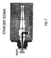
- this known sensor is a contactless single-point laser sensor based on a conoscopic holography technique. It has a laser diode whose emitted laser beam is deflected via a prism or mirror device in the direction of a lens mounted on a housing and focused on the surface of an object to be scanned. From there, the laser beam is reflected back into the sensor, focused on a conoscopic module by means of a focusing lens and finally recorded by a CCD camera / sensor.
- the known laser sensor is used for scanning, for example, workpiece surfaces, which are accessible from the outside with the laser. By changing the lens, however, the working range of the sensor can be increased. It has, however, been found that, in particular, laser sensors of the above type can only be converted over a very long time to different working ranges by corresponding replacement of the lenses and optics.
- US-A-4 561 776 is an electro-optical sensor to remove, which is removed from a magazine by means of a robot and inserted into a machine head.
- the measuring beam of the sensor runs in the longitudinal axis direction of the sensor.
- a coordinate measuring machine with an optical probe is from EP-A-0 362 625 known.
- the probe has a replaceable front optics, which contains a lighting optics. Along the longitudinal axis of the probe runs the measuring beam.
- the present invention is therefore an object of the invention to provide a Konscheintiksystem for coordinate measuring machines of this type, which increases the flexibility and efficiency of the coordinate measuring machine.
- the exchangeable optical system according to the invention substantially exists from a number of interchangeable lenses, preferably with different laser beam exit angles, the interchangeable optics having an adapter piece for connection to the coordinate measuring machine, the adapter piece is followed by a tubular element or a receiving base, which extends in the laser exit direction of the CMM and the / at his distal end carries a deflecting device for deflecting the laser beam at a predetermined angle.
- the adapter piece has a permanent magnet to allow a quick mounting of the optics on the housing of the coordinate device.
- the interchangeable lenses are bunkered in a magazine, whereby a preferably computer-controlled (automated) access to the individual optics can be achieved.
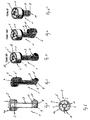
- Fig. 1 consists of the exchange optics 1 according to a first preferred embodiment of the invention essentially of an adapter piece 2 for connecting the respective exchange optics 1 to a (not further shown in the figures) coordinate measuring machine on which a tubular element 3 or a receiving base is arranged.
- the adapter piece 2 is presently made of a magnetic core or permanent magnet 4 (see Fig. 6 ), which is inserted into a cylindrical housing 5.
- a counter electromagnet 4a to the permanent magnet in the adapter piece 2 is arranged, which is turned on only for the disassembly of the exchange optics 1 from the meter housing and thereby exerts a repulsive force, which superimposes the attraction of the permanent magnet 4.
- a central through-hole 6 is formed, the alignment and dimensioning of the outlet opening of the already known coordinate measuring machine is adjusted.
- the type and structure of the particular adapter piece 2 is selected in dependence of the coordinate measuring machine to be equipped therewith and therefore may differ from each other in different coordinate measuring machines.
- the pipe element 3 is flanged frontally, ie at its side facing away from the mounting side.
- the length of the tubular element 3 is application-based and may vary from optic to optic.
- a receptacle 7 for a laser beam deflection device 8 At the distal end of the tubular element 3 there is a receptacle 7 for a laser beam deflection device 8. In the present case, this consists of a mirror 3 oriented obliquely to the tube element 3 or a prism 9, which is designed such that an incident laser beam guided through the tube element 3 under a certain angle is deflected or deflected.
- a laser beam outlet opening 10 which is aligned so that the already deflected or deflected laser beam is passed through this to the outside.
- the exit opening 10 itself is preferably another lens system or optics 11 for focusing the exiting laser beam on an object to be scanned.
- the pipe element 3 via three screws 12 (see, for example Fig. 3 to 6 ) are mounted on the adapter piece 2, which also serve as centering devices. After loosening the three screws 12, the tubular element 3 can be rotated in this case in a 1/3 circle step and then fixed again by tightening the screws 12. Depending on the flange construction, a continuous rotation is possible.
- a magnetically effected assembly of the exchangeable lens 1 on the coordinate measuring machine is advantageous in that it allows a quick change of the optics 1 without loosening and closing of closures or screws, wherein in addition a magnetic assembly is extremely universally feasible as long as the housing, not shown, of the coordinate measuring machine, at least in the connection area of the exchange optics 1 consists of a metal material or is provided with a metal part.
- a bayonet or plug closure is conceivable.
- exchangeable lens 1 in the region of the adapter piece 2 or within the adjoining pipe element 3 with a further optical system or lens unit, which is adapted to the coordinate measuring machine to be equipped.
- different optics 1 are stored according to the invention in a magazine and can thus optionally removed, for example by a not shown loading device and the laser beam Outlet opening of the CMM are mounted.
- the present invention relates to an exchangeable optics system for coordinate measuring machines with laser sensor technology consisting of a number of interchangeable lenses with different laser beam exit angles, each of which interchangeable optics has an adapter piece for connecting the respective interchangeable optics to the coordinate measuring machine, which is followed by a tubular element or a receiving base / extending in the laser exit direction of the coordinate measuring machine and carries at its distal end a deflection device for deflecting the laser beam at a predetermined angle.
Landscapes
- Physics & Mathematics (AREA)
- General Physics & Mathematics (AREA)
- Length Measuring Devices By Optical Means (AREA)
Description
- Die vorliegende Erfindung betrifft ein Koordinatenmessgerät mit Wechseloptik und insbesondere ein Wechseloptiksystem für Koordinatenmessgeräte mit Lasersensor-Technik.
- Koordinatenmessgeräte dienen beispielsweise zur Abtastung von Werkstückoberflächen in der Metallverarbeitung insbesondere zur Bestimmung der Oberflächenqualität und Maßhaltigkeit des jeweiligen Werkstücks. Aus dem Stand der Technik sind eine Vielzahl von Koordinatenmessgeräten bekannt, mittels denen auf möglichst einfache Weise unterschiedliche Messungen beispielsweise von Werkstückoberflächen, Aushöhlungen (Bohrungen) oder auch Hinterschneidungen durchführbar sind.
- Beispielsweise aus der
DE 44 45 331 A1 ist ein Koordinatenmessgerät mit einem automatischen Multisensormesskopf bekannt, der aus einer Trägerplatte besteht, auf der eine Anzahl unterschiedlich geformter mechanischer Abtastvorrichtungen (Sensoren) gelagert sind. Diese sind individuell mittels zugehöriger Linearantriebe in eine Abtastposition bzw. eine Rastposition verfahrbar, sodass je nach Art der abzutastenden Oberfläche oder je nach Art des Werkstücks (Innenbohrung, äußere plane Fläche, Zylindermantel und dgl.) der jeweils geeignete Sensor in seine Abtastposition gebracht werden kann, ohne dass dieser von den anderen Sensoren während des Abtastvorgangs behindert wird. - Mechanische Sensoren werden neuerdings zunehmend durch berührungslos arbeitende Sensoren vorzugsweise basierend auf Lasertechnologie ersetzt. Mit sogenannten linearen konoskopischen (holografischen) Lasersensoren lässt sich ein konoskopisches Interferogramm eines Gegenstands oder Werkstücks erzeugen, welches mittels einer CCD Kamera aufgezeichnet werden kann. Der Vorteil dieser bekannten Technik besteht darin, dass lediglich nur eine einzige Kamera für das Bestimmen der Kontur des abzutastenden Objekts erforderlich ist, ohne dass die Notwendigkeit der Anordnung beispielsweise eines Referenzstrahls besteht. Im Stand der Technik ist ein derartiger konoskopischer Holograf der Firma "OPTIMET" unter der Bezeichnung "CONOPROBE" bekannt geworden, wie er prinzipiell in der anliegenden
Fig. 7 dargestellt ist. - Bei diesem bekannten Sensor handelt es sich demzufolge um einen berührungslosen Einpunkt-Lasersensor basierend auf einer konoskopischen Holografietechnik. Er besitzt eine Laserdiode, deren ausgesendeter Laserstrahl über eine Prismen- oder Spiegeleinrichtung in Richtung eines an einem Gehäuse montierten Objektivs umgelenkt und auf die Oberfläche eines abzutastenden Objekts fokussiert wird. Von dort wird der Laserstrahl in den Sensor zurück reflektiert, mittels einer Scharfstelllinse auf ein Konoskopiemodul fokussiert und schließlich durch eine CCD Kamera/Sensor aufgezeichnet. Wie aus dieser Beschreibung ersichtlich ist, wird der bekannte Lasersensor zur Abtastung beispielsweise von Werkstückoberflächen eingesetzt, welche von Außen mit dem Laser erreichbar sind. Durch Wechseln des Objektivs kann jedoch der Arbeitsbereich des Sensors gesteigert werden. Es hat sich dabei indessen gezeigt, dass insbesondere Lasersensoren der vorstehenden Bauart nur sehr zeitaufwendig auf unterschiedliche Arbeitsbereiche durch entsprechendes Austauschen der Linsen und Optiken umgestellt werden können.
- Der
US-A-4 561 776 ist ein elektrooptischer Sensor zu entnehmen, der aus einem Magazin mittels eines Roboters entnommen und in einen Maschinenkopf eingesetzt wird. Der Messstrahl des Sensors verläuft in Längsachsenrichtung des Sensors. - Ein Koordinatenmessgerät mit einem optischen Tastkopf ist aus der
EP-A-0 362 625 bekannt. Der Tastkopf weist eine auswechselbare Frontoptik auf, die eine Beleuchtungsoptik enthält. Entlang der Längsachse des Tastkopfs verläuft der Messstrahl. - Der vorliegenden Erfindung liegt daher die Aufgabe zugrunde, ein Wechseloptiksystem für Koordinatenmessgeräte dieser Gattung zu schaffen, welches die Flexibilität und Effizienz des Koordinatenmessgeräts erhöht.
- Diese Aufgabe wird durch ein Wechseloptiksystem mit den Merkmalen des anliegenden Patentanspruchs 1 gelöst. Demzufolge besteht das erfindungsgemäße Wechseloptiksystem im wesentlichen aus einer Anzahl von Wechseloptiken vorzugsweise mit unterschiedlichen Laserstrahlaustrittswinkeln, wobei die Wechseloptik ein Adapterstück für das Anschließen an das Koordinatenmessgerät hat, an das Adapterstück schließt sich ein Rohrelement oder ein Aufnahmesockel an, das/der sich in Laseraustrittsrichtung des Koordinatenmessgeräts erstreckt und das/der an seinem distalen Ende eine Umlenkeinrichtung für ein Umlenken des Laserstrahls unter einem vorbestimmten Winkel trägt.
- Vorzugsweise hat das Adapterstück einen Permanentmagneten, um ein schnelles Montieren der Optik am Gehäuse des Koordinatengeräts zu ermöglichen.
- Weiter vorzugsweise sind die Wechseloptiken in einem Magazin gebunkert, wodurch ein vorzugsweise rechnergesteuerter (automatisierter) Zugriff auf die einzelnen Optiken erreicht werden kann.
- Weitere vorteilhafte Ausgestaltungen sind Gegenstand der übrigen Unteransprüche.
- Die Erfindung wird nachstehend anhand bevorzugter Ausführungsbeispiele unter Bezugnahme auf die begleitenden Zeichnungen näher erläutert.
- Es zeigen
-
Fig. 1 den Seitenriss einer Wechseloptik gemäß einem ersten bevorzugten Ausführungsbeispiel der Erfindung, -
Fig. 2 die aufgebrochene Perspektivenansicht der Wechseloptik gemäßFig. 1 , -
Fig. 3 bis 5 jeweils die aufgebrochene Perspektivenansicht weiterer drei Ausführungsbeispiele der Erfindung, -
Fig. 6 die Draufsicht auf die Anschlussstirnseite der erfindungsgemäßen Wechseloptik und -
Fig. 7 den prinzipiellen Seitenschnitt eines Lasersensors gemäß dem Stand der Technik. - Gemäß der
Fig. 1 besteht die Wechseloptik 1 gemäß einem ersten bevorzugten Ausführungsbeispiel der Erfindung im wesentlichen aus einem Adapterstück 2 für das Anschließen der jeweiligen Wechseloptik 1 an ein (in den Figuren nicht weiter gezeigtes) Koordinatenmessgerät, an dem ein Rohrelement 3 oder ein Aufnahmesockel angeordnet ist. Das Adapterstück 2 ist vorliegend aus einem magnetischen Kern oder Permanentmagneten 4 (sieheFig. 6 ) gebildet, der in ein zylinderförmiges Gehäuse 5 eingesetzt ist. Zusätzlich ist ein zu dem Permanentmagnet gegenpoliger Elektromagnet 4a im Adapterstück 2 angeordnet, der lediglich für die Demontage der Wechseloptik 1 vom Messgerätegehäuse eingeschaltet wird und dabei eine Abstoßkraft ausübt, welche die Anziehungskraft des Permanentmagneten 4 überlagert. Im Adapterstück 2 ist eine zentrale Durchgangsbohrung 6 ausgebildet, deren Ausrichtung und Dimensionierung der Austrittsöffnung des bereits bekannten Koordinatenmessgeräts angepasst ist. In anderen Worten ausgedrückt ist die Art und der Aufbau insbesondere des Adapterstücks 2 in Abhängigkeit des damit zu bestückenden Koordinatenmessgeräts gewählt und kann daher bei verschiedenen Koordinatenmessgeräten voneinander abweichen. - An dem Adapterstück 2 ist stirnseitig, d.h. an seinem der Montageseite abgewandten Seite das Rohrelement 3 angeflanscht. Die Länge des Rohrelements 3 ist anwendungsbezogen bemessen und kann von Optik zu Optik unterschiedlich sein. Am distalen Ende des Rohrelements 3 befindet sich eine Aufnahme 7 für eine Laserstrahl-Umlenkvorrichtung 8. Diese besteht vorliegend aus einem zum Rohrelement 3 schräg ausgerichteten Spiegel oder einem Prisma 9, der/das so ausgebildet ist, dass ein durch das Rohrelement 3 geleiteter einfallender Laserstrahl unter einem bestimmten Winkel ab- bzw. umgelenkt wird. In der Aufnahme befindet sich eine Laserstrahl-Austrittsöffnung 10, die so ausgerichtet ist, dass der bereits ab- bzw. umgelenkte Laserstrahl durch diese nach Außen geleitet wird. In der Austrittöffnung 10 selbst befindet sich vorzugsweise ein weiteres Linsensystem bzw. Optik 11 zur Fokussierung des austretenden Laserstrahls auf ein abzutastendes Objekt.
- In den
Fig. 3 bis 5 sind erfindungsgemäße Wechseloptiken 1 mit unterschiedlichen Austrittswinkeln gezeigt. Demnach sind Wechseloptiken mit Austrittswinkeln von 0°, 90° sowie 180° bezüglich des Lasereinfallwinkels vorgesehen, wobei natürlich auch andere Ausfallwinkel je nach Anwendungsfall möglich sind. Optional kann auch die Anflanschstelle zwischen dem Adapterstück 2 und dem Rohrelement 3 und/oder die Verbindungsstelle zwischen dem Rohrelement 3 und der Aufnahme 7 drehbar ausgeführt sein, wodurch eine Rotation des Rohrelements 3 und/oder der Aufnahme 7 um dessen/deren Hochachse bei feststehendem Adapterstück 2 möglich wird. - Im vorliegenden Fall ist das Rohrelement 3 über drei Schrauben 12 (siehe beispielsweise
Fig. 3 bis 6 ) an das Adapterstück 2 montiert, welche gleichzeitig als Zentriereinrichtungen dienen. Nach Lösen der drei Schrauben 12 kann das Rohrelement 3 vorliegend in einem 1/3 Kreisschritt gedreht und anschließend wieder durch Festziehen der Schrauben 12 fixiert werden. Je nach Anflanschkonstruktion ist auch eine kontinuierliche Verdrehung möglich. - Auch ist es denkbar, die Aufnahme 7 schwenkbar am distalen Ende des Rohrstücks 3 zu lagern, derart, dass bei einer scharnierartigen Verschwenkung der Aufnahme 7 die darin befindliche Umlenkvorrichtung mit verschwenkt und damit der Laseraustrittswinkel gerastet oder kontinuierlich verstellbar ist.
- Wie eingangs bereits ausgeführt wurde, ist eine magnetisch bewirkte Montage der Wechseloptik 1 am Koordinatenmessgerät insofern vorteilhaft, als dass hierdurch ein schneller Wechsel der Optik 1 ohne Lösen und Schließen von Verschlüssen oder Schrauben ermöglicht wird, wobei darüber hinaus eine Magnet-Montage äußerst universell durchführbar ist, solange das nicht gezeigte Gehäuse des Koordinatenmessgeräts zumindest im Anschlussbereich der Wechseloptik 1 aus einem Metallmaterial besteht oder mit einem Metallteil versehen ist. Jedoch ist alternativ auch ein Bajonett- oder Steckverschluss denkbar.
- Auch ist es optional möglich, die Wechseloptik 1 im Bereich des Adapterstücks 2 oder innerhalb des sich daran anschließenden Rohrelements 3 mit einer weiteren Optik bzw. Linseneinheit auszurüsten, welche an das zu bestückende Koordinatenmessgerät angepasst ist.
- Um einen schnellen Wechsel der Optik 1 und damit ein schnelles Umrüsten des Koordinatenmessgeräts auf einen anderen Anwendungszweck auch rechnergestützt zu erreichen, sind unterschiedliche Optiken 1 gemäß der Erfindung in einem Magazin gelagert und können so beispielsweise durch eine nicht weiter dargestellte Bestückungseinrichtung wahlweise entnommen und an der Laserstrahl-Austrittöffnung des Koordinatenmessgeräts montiert werden.
- Die vorliegende Erfindung betrifft ein Wechseloptiksystem für Koordinatenmessgeräte mit Lasersensor-Technik bestehend aus einer Anzahl von Wechseloptiken mit unterschiedlichen Laserstrahlaustrittswinkeln, von denen jede Wechseloptik ein Adapterstück für das Anschließen der jeweiligen Wechseloptik an das Koordinatenmessgerät hat, an das sich ein Rohrelement oder ein Aufnahmesockel anschließt, das/der sich in Laseraustrittsrichtung aus dem Koordinatenmessgerät erstreckt und an seinem distalen Ende eine Umlenkeinrichtung für ein Umlenken des Laserstrahls unter einem vorbestimmten Winkel trägt.
Claims (8)
- Wechseloptiksystem für Koordinatenmessgeräte mit Einpunkt-Lasersensor-Technik bestehend aus einer Anzahl von Wechseloptiken (1), von denen jede Wechseloptik (1) ein Adapterstück (2) für das Anschließen der jeweiligen Wechseloptik (1) an das Koordinatenmessgerät hat, an das sich ein Rohrelement (3) oder ein Aufnahmcsockel anschließt, das/der sich in Laseraustrittsrichtung des Koordinatenmessgeräts erstreckt und an seinem distalen Ende eine Ab- oder Umlenkeinrichtung (8) für ein Ab- /Umlenken des aus dem Rohrelement / dem Adapter austretenden Laserstrahls unter einem vorbestimmten Winkel trägt.
- Wechseloptiksystem nach Anspruch 1, dadurch gekennzeichnet, dass die unterschiedlichen Wechseloptiken (1) Austrittswinkel von 0°, 90° und 180° aufweisen.
- Wechseloptiksystem nach einem der vorstehenden Ansprüche, dadurch gekennzeichnet, dass das Adapterstück (2) mit einem Schnellverschluss vorzugsweise einem Bajonett- oder Steckverschluss für das Montieren an dem Koordinatenmessgerät versehen ist.
- Wechseloptiksystem nach einem der vorstehenden Ansprüche, dadurch gekennzeichnet, dass das Adapterstück (2) mit einem Permanentmagneten (4) ausgerüstet ist, der mit einem Gehäuse oder Gehäuseteil des Koordinatenmessgeräts für die Montage der Wechseloptik in Hafteingriff bringbar ist.
- Wechseloptiksystem nach einem der vorstehenden Ansprüche, dadurch gekennzeichnet, dass das Adapterstück (2) mit einer Zentriervorrichtung ausgebildet ist für ein Zentrieren der Wechseloptik (1) bezüglich der Austrittsrichtung und Austrittsstelle des Laserstrahls aus dem Koordinatenmessgerät.
- Wechseloptiksystem nach einem der vorstehenden Ansprüche, dadurch gekennzeichnet, dass die Ab-/Umlenkeinrichtung (8) ein Prisma oder Spiegel (9) aufweist, der in einem Aufnahmeteil (7) am distalen Ende des Rohrelements oder Aufnahmesockels (3) fixiert ist.
- Wechseloptiksystem nach einem der vorstehenden Ansprüche, dadurch gekennzeichnet, dass die Umlenkeinrichtung (8) eine Linse oder ein Linsensystem (11) für ein Fokussieren des ab-/umgelenkten Laserstrahls auf ein abzutastendes Objekt aufweist.
- Wechseloptiksystem nach einem der vorstehenden Ansprüche, gekennzeichnet durch ein Magazin zur Aufnahme und Bereitstellung von Wechseloptiken (1) vorzugsweise mit unterschiedlichen Austrittswinkeln und/oder unterschiedlichen Rohrelementlängen.
Applications Claiming Priority (2)
| Application Number | Priority Date | Filing Date | Title |
|---|---|---|---|
| DE200410014153 DE102004014153A1 (de) | 2004-03-23 | 2004-03-23 | Koordinatenmessgerät mit Wechseloptik |
| DE102004014153 | 2004-03-23 |
Publications (3)
| Publication Number | Publication Date |
|---|---|
| EP1580521A2 EP1580521A2 (de) | 2005-09-28 |
| EP1580521A3 EP1580521A3 (de) | 2009-02-11 |
| EP1580521B1 true EP1580521B1 (de) | 2013-08-07 |
Family
ID=34854005
Family Applications (1)
| Application Number | Title | Priority Date | Filing Date |
|---|---|---|---|
| EP20050005759 Expired - Lifetime EP1580521B1 (de) | 2004-03-23 | 2005-03-16 | Koordinatenmessgerät mit Wechseloptik |
Country Status (2)
| Country | Link |
|---|---|
| EP (1) | EP1580521B1 (de) |
| DE (1) | DE102004014153A1 (de) |
Families Citing this family (18)
| Publication number | Priority date | Publication date | Assignee | Title |
|---|---|---|---|---|
| US7876454B2 (en) | 2006-12-20 | 2011-01-25 | General Electric Company | Method and system for measurement of a cutting tool |
| US7768655B2 (en) * | 2006-12-20 | 2010-08-03 | General Electric Company | Methods and system for measuring an object |
| DE102007008361B3 (de) | 2007-02-16 | 2008-04-03 | Isis Sentronics Gmbh | Abtastsensorsystem zum berührungslosen optischen Abtasten von Objektoberflächen |
| DE102007000306B4 (de) | 2007-05-08 | 2015-07-09 | Werth Messtechnik Gmbh | Koordinatenmessvorrichtung |
| DE102007054915A1 (de) * | 2007-11-15 | 2009-05-20 | Precitec Optronik Gmbh | Messvorrichtung, Messkopf und Messkopfhalter |
| US7924439B2 (en) | 2008-09-29 | 2011-04-12 | General Electric Company | Method and system for parameter extraction of a cutting tool |
| US9615482B2 (en) | 2009-12-11 | 2017-04-04 | General Electric Company | Shaped heat sinks to optimize flow |
| US10274263B2 (en) | 2009-04-09 | 2019-04-30 | General Electric Company | Method and apparatus for improved cooling of a heat sink using a synthetic jet |
| US9478479B2 (en) | 2010-10-26 | 2016-10-25 | General Electric Company | Thermal management system and method |
| DE102009019129A1 (de) | 2009-04-29 | 2010-11-04 | Breitmeier Messtechnik Gmbh | Vorrichtung zur Positionierung eines Sensors |
| US8112172B2 (en) | 2009-04-29 | 2012-02-07 | General Electric Company | Method and system for gash parameter extraction of a cutting tool |
| DE102012103502A1 (de) | 2011-04-21 | 2012-10-25 | Werth Messtechnik Gmbh | Anordnung zur Befestigung von Sonden eines Sensors an einem Koordinatenmessgerät |
| EP2795243B1 (de) | 2011-12-21 | 2016-04-20 | Carl Zeiss Industrielle Messtechnik GmbH | Koordinatenmessgerät mit verbesserter schnittstellenanordnung |
| EP2795244B1 (de) | 2011-12-21 | 2018-02-07 | Carl Zeiss Industrielle Messtechnik GmbH | Verfahren zum koppeln zweier systemkomponenten eines messgeräts, insbesondere eines koordinatenmessgeräts |
| WO2013167167A1 (de) | 2012-05-07 | 2013-11-14 | Carl Zeiss Industrielle Messtechnik Gmbh | Wechselbares beleuchtungsmodul für ein koordinatenmessgerät |
| US8817240B2 (en) | 2012-05-25 | 2014-08-26 | Mitutoyo Corporation | Interchangeable optics configuration for a chromatic range sensor optical pen |
| DE112014006641A5 (de) * | 2014-05-05 | 2017-01-26 | Carl Zeiss Industrielle Messtechnik Gmbh | Koordinatenmessgerät zum Bestimmen von geometrischen Eigenschaften eines Messobjekts |
| DE102021101749A1 (de) | 2021-01-27 | 2022-07-28 | Carl Zeiss Industrielle Messtechnik Gmbh | Schnittstellenanordnung zur kopplung von systemkomponenten einer messvorrichtung |
Family Cites Families (2)
| Publication number | Priority date | Publication date | Assignee | Title |
|---|---|---|---|---|
| US4561776A (en) * | 1981-03-25 | 1985-12-31 | Diffracto Ltd. | Electro-optical sensors for tool and robotic inspection |
| DE3834117A1 (de) * | 1988-10-07 | 1990-04-12 | Zeiss Carl Fa | Koordinatenmessgeraet mit einem optischen tastkopf |
-
2004
- 2004-03-23 DE DE200410014153 patent/DE102004014153A1/de not_active Withdrawn
-
2005
- 2005-03-16 EP EP20050005759 patent/EP1580521B1/de not_active Expired - Lifetime
Also Published As
| Publication number | Publication date |
|---|---|
| EP1580521A2 (de) | 2005-09-28 |
| DE102004014153A1 (de) | 2005-10-13 |
| EP1580521A3 (de) | 2009-02-11 |
Similar Documents
| Publication | Publication Date | Title |
|---|---|---|
| EP1580521B1 (de) | Koordinatenmessgerät mit Wechseloptik | |
| DE10297255B4 (de) | Verfahren und Vorrichtung zum Überwachen und Einstellen eines Laserschweißprozesses | |
| EP3312554B1 (de) | Messsystem zur messung an werkzeugen in einer werkzeugmaschine | |
| DE3834117A1 (de) | Koordinatenmessgeraet mit einem optischen tastkopf | |
| DE102007028504A1 (de) | Vorrichtung zum Bearbeiten eines Werkstücks mittels eines Laserstrahls | |
| DE102006050235B4 (de) | Kamerasystem zum Überwachen eines Raumbereichs | |
| DE19944484C1 (de) | Wechselvorrichtung für einen Linsenhalter eines Anschlusskopfs zur Bearbeitung eines Werkstücks mittels eines Laserstrahls | |
| EP1762328B1 (de) | Taktil geführte Laserbearbeitungsoptik | |
| DE102007062535A1 (de) | Verfahren und Einrichtung zum Fügen | |
| DE202011000456U1 (de) | Fügeeinrichtung | |
| EP0156231A2 (de) | Vorrichtung zur Bearbeitung von Werkstücken durch einen Energiestrahl hoher Leistungsdichte, insbesondere einen Laserstrahl eines CO2-Lasers | |
| EP1031866A3 (de) | Relaisoptik für ein Ablenksystem sowie ein Ablenksystem | |
| EP3357633B1 (de) | Messsystem zur messung an werkzeugen in einer werkzeugmaschine | |
| WO2019201558A1 (de) | Adapter für ein objektiv, vorrichtung zum halten des adapters und stellvorrichtung | |
| DE69230222T2 (de) | Verfahren zur fixierung eines optischen bildsensors in ausrichtung zur bildfläche einer linsenanordnung | |
| DE202004013136U1 (de) | Modulare Lichtwellenoptik | |
| EP1039157B1 (de) | Vorrichtung zum Haltern eines Teils und Anwendung der Vorrichtung | |
| DE2918024C2 (de) | Justiereinrichtung für eine Lichtleitfaserverbindung mit Linsenkopplung | |
| DE102005050274A1 (de) | Koppelvorrichtung für eine Lichtführung | |
| DE3930629A1 (de) | Vorrichtung zum parallelen ausrichten der auflageflaechen zweier bauteile und verfahren zum betrieb der vorrichtung | |
| EP1698996B1 (de) | Identifikationseinrichtung | |
| DE69511606T2 (de) | Vorrichtung zur Profilmessung einer ebenen Oberfläche | |
| DE29904489U1 (de) | Arbeitskopf zur Bearbeitung eines Werkstücks mittels eines Laserstrahls | |
| EP1041358A2 (de) | Fluchtungsmessanordnung | |
| DE10130199B4 (de) | Scannervorrichtung für einen Leistungslaser |
Legal Events
| Date | Code | Title | Description |
|---|---|---|---|
| PUAI | Public reference made under article 153(3) epc to a published international application that has entered the european phase |
Free format text: ORIGINAL CODE: 0009012 |
|
| 17P | Request for examination filed |
Effective date: 20050316 |
|
| AK | Designated contracting states |
Kind code of ref document: A2 Designated state(s): AT BE BG CH CY CZ DE DK EE ES FI FR GB GR HU IE IS IT LI LT LU MC NL PL PT RO SE SI SK TR |
|
| AX | Request for extension of the european patent |
Extension state: AL BA HR LV MK YU |
|
| PUAL | Search report despatched |
Free format text: ORIGINAL CODE: 0009013 |
|
| AK | Designated contracting states |
Kind code of ref document: A3 Designated state(s): AT BE BG CH CY CZ DE DK EE ES FI FR GB GR HU IE IS IT LI LT LU MC NL PL PT RO SE SI SK TR |
|
| AX | Request for extension of the european patent |
Extension state: AL BA HR LV MK YU |
|
| 17Q | First examination report despatched |
Effective date: 20090507 |
|
| AKX | Designation fees paid |
Designated state(s): AT BE BG CH CY CZ DE DK EE ES FI FR GB GR HU IE IS IT LI LT LU MC NL PL PT RO SE SI SK TR |
|
| RAP1 | Party data changed (applicant data changed or rights of an application transferred) |
Owner name: WERTH MESSTECHNIK GMBH |
|
| GRAP | Despatch of communication of intention to grant a patent |
Free format text: ORIGINAL CODE: EPIDOSNIGR1 |
|
| GRAS | Grant fee paid |
Free format text: ORIGINAL CODE: EPIDOSNIGR3 |
|
| GRAP | Despatch of communication of intention to grant a patent |
Free format text: ORIGINAL CODE: EPIDOSNIGR1 |
|
| GRAA | (expected) grant |
Free format text: ORIGINAL CODE: 0009210 |
|
| INTG | Intention to grant announced |
Effective date: 20130613 |
|
| AK | Designated contracting states |
Kind code of ref document: B1 Designated state(s): AT BE BG CH CY CZ DE DK EE ES FI FR GB GR HU IE IS IT LI LT LU MC NL PL PT RO SE SI SK TR |
|
| REG | Reference to a national code |
Ref country code: GB Ref legal event code: FG4D Free format text: NOT ENGLISH |
|
| REG | Reference to a national code |
Ref country code: CH Ref legal event code: EP Ref country code: AT Ref legal event code: REF Ref document number: 625945 Country of ref document: AT Kind code of ref document: T Effective date: 20130815 |
|
| REG | Reference to a national code |
Ref country code: IE Ref legal event code: FG4D Free format text: LANGUAGE OF EP DOCUMENT: GERMAN |
|
| REG | Reference to a national code |
Ref country code: DE Ref legal event code: R096 Ref document number: 502005013892 Country of ref document: DE Effective date: 20131002 |
|
| REG | Reference to a national code |
Ref country code: DE Ref legal event code: R082 Ref document number: 502005013892 Country of ref document: DE Representative=s name: STOFFREGEN, HANS-HERBERT, DIPL.-PHYS. DR.RER.N, DE |
|
| REG | Reference to a national code |
Ref country code: CH Ref legal event code: NV Representative=s name: LUCHS AND PARTNER PATENTANWAELTE, CH |
|
| REG | Reference to a national code |
Ref country code: NL Ref legal event code: VDEP Effective date: 20130807 |
|
| REG | Reference to a national code |
Ref country code: LT Ref legal event code: MG4D |
|
| PG25 | Lapsed in a contracting state [announced via postgrant information from national office to epo] |
Ref country code: CY Free format text: LAPSE BECAUSE OF FAILURE TO SUBMIT A TRANSLATION OF THE DESCRIPTION OR TO PAY THE FEE WITHIN THE PRESCRIBED TIME-LIMIT Effective date: 20130619 Ref country code: IS Free format text: LAPSE BECAUSE OF FAILURE TO SUBMIT A TRANSLATION OF THE DESCRIPTION OR TO PAY THE FEE WITHIN THE PRESCRIBED TIME-LIMIT Effective date: 20131207 Ref country code: PT Free format text: LAPSE BECAUSE OF FAILURE TO SUBMIT A TRANSLATION OF THE DESCRIPTION OR TO PAY THE FEE WITHIN THE PRESCRIBED TIME-LIMIT Effective date: 20131209 Ref country code: LT Free format text: LAPSE BECAUSE OF FAILURE TO SUBMIT A TRANSLATION OF THE DESCRIPTION OR TO PAY THE FEE WITHIN THE PRESCRIBED TIME-LIMIT Effective date: 20130807 Ref country code: SE Free format text: LAPSE BECAUSE OF FAILURE TO SUBMIT A TRANSLATION OF THE DESCRIPTION OR TO PAY THE FEE WITHIN THE PRESCRIBED TIME-LIMIT Effective date: 20130807 |
|
| PG25 | Lapsed in a contracting state [announced via postgrant information from national office to epo] |
Ref country code: GR Free format text: LAPSE BECAUSE OF FAILURE TO SUBMIT A TRANSLATION OF THE DESCRIPTION OR TO PAY THE FEE WITHIN THE PRESCRIBED TIME-LIMIT Effective date: 20131108 Ref country code: SI Free format text: LAPSE BECAUSE OF FAILURE TO SUBMIT A TRANSLATION OF THE DESCRIPTION OR TO PAY THE FEE WITHIN THE PRESCRIBED TIME-LIMIT Effective date: 20130807 Ref country code: NL Free format text: LAPSE BECAUSE OF FAILURE TO SUBMIT A TRANSLATION OF THE DESCRIPTION OR TO PAY THE FEE WITHIN THE PRESCRIBED TIME-LIMIT Effective date: 20130807 Ref country code: FI Free format text: LAPSE BECAUSE OF FAILURE TO SUBMIT A TRANSLATION OF THE DESCRIPTION OR TO PAY THE FEE WITHIN THE PRESCRIBED TIME-LIMIT Effective date: 20130807 Ref country code: PL Free format text: LAPSE BECAUSE OF FAILURE TO SUBMIT A TRANSLATION OF THE DESCRIPTION OR TO PAY THE FEE WITHIN THE PRESCRIBED TIME-LIMIT Effective date: 20130807 |
|
| PG25 | Lapsed in a contracting state [announced via postgrant information from national office to epo] |
Ref country code: CY Free format text: LAPSE BECAUSE OF FAILURE TO SUBMIT A TRANSLATION OF THE DESCRIPTION OR TO PAY THE FEE WITHIN THE PRESCRIBED TIME-LIMIT Effective date: 20130807 |
|
| PG25 | Lapsed in a contracting state [announced via postgrant information from national office to epo] |
Ref country code: SK Free format text: LAPSE BECAUSE OF FAILURE TO SUBMIT A TRANSLATION OF THE DESCRIPTION OR TO PAY THE FEE WITHIN THE PRESCRIBED TIME-LIMIT Effective date: 20130807 Ref country code: RO Free format text: LAPSE BECAUSE OF FAILURE TO SUBMIT A TRANSLATION OF THE DESCRIPTION OR TO PAY THE FEE WITHIN THE PRESCRIBED TIME-LIMIT Effective date: 20130807 Ref country code: CZ Free format text: LAPSE BECAUSE OF FAILURE TO SUBMIT A TRANSLATION OF THE DESCRIPTION OR TO PAY THE FEE WITHIN THE PRESCRIBED TIME-LIMIT Effective date: 20130807 Ref country code: EE Free format text: LAPSE BECAUSE OF FAILURE TO SUBMIT A TRANSLATION OF THE DESCRIPTION OR TO PAY THE FEE WITHIN THE PRESCRIBED TIME-LIMIT Effective date: 20130807 Ref country code: DK Free format text: LAPSE BECAUSE OF FAILURE TO SUBMIT A TRANSLATION OF THE DESCRIPTION OR TO PAY THE FEE WITHIN THE PRESCRIBED TIME-LIMIT Effective date: 20130807 |
|
| PG25 | Lapsed in a contracting state [announced via postgrant information from national office to epo] |
Ref country code: ES Free format text: LAPSE BECAUSE OF FAILURE TO SUBMIT A TRANSLATION OF THE DESCRIPTION OR TO PAY THE FEE WITHIN THE PRESCRIBED TIME-LIMIT Effective date: 20130807 |
|
| PLBE | No opposition filed within time limit |
Free format text: ORIGINAL CODE: 0009261 |
|
| STAA | Information on the status of an ep patent application or granted ep patent |
Free format text: STATUS: NO OPPOSITION FILED WITHIN TIME LIMIT |
|
| 26N | No opposition filed |
Effective date: 20140508 |
|
| REG | Reference to a national code |
Ref country code: DE Ref legal event code: R097 Ref document number: 502005013892 Country of ref document: DE Effective date: 20140508 |
|
| PG25 | Lapsed in a contracting state [announced via postgrant information from national office to epo] |
Ref country code: LU Free format text: LAPSE BECAUSE OF FAILURE TO SUBMIT A TRANSLATION OF THE DESCRIPTION OR TO PAY THE FEE WITHIN THE PRESCRIBED TIME-LIMIT Effective date: 20140316 |
|
| REG | Reference to a national code |
Ref country code: IE Ref legal event code: MM4A |
|
| PG25 | Lapsed in a contracting state [announced via postgrant information from national office to epo] |
Ref country code: IE Free format text: LAPSE BECAUSE OF NON-PAYMENT OF DUE FEES Effective date: 20140316 |
|
| REG | Reference to a national code |
Ref country code: AT Ref legal event code: MM01 Ref document number: 625945 Country of ref document: AT Kind code of ref document: T Effective date: 20140316 |
|
| PG25 | Lapsed in a contracting state [announced via postgrant information from national office to epo] |
Ref country code: AT Free format text: LAPSE BECAUSE OF NON-PAYMENT OF DUE FEES Effective date: 20140316 |
|
| REG | Reference to a national code |
Ref country code: FR Ref legal event code: PLFP Year of fee payment: 12 |
|
| PGFP | Annual fee paid to national office [announced via postgrant information from national office to epo] |
Ref country code: CH Payment date: 20160323 Year of fee payment: 12 |
|
| PG25 | Lapsed in a contracting state [announced via postgrant information from national office to epo] |
Ref country code: BG Free format text: LAPSE BECAUSE OF FAILURE TO SUBMIT A TRANSLATION OF THE DESCRIPTION OR TO PAY THE FEE WITHIN THE PRESCRIBED TIME-LIMIT Effective date: 20130807 Ref country code: MC Free format text: LAPSE BECAUSE OF FAILURE TO SUBMIT A TRANSLATION OF THE DESCRIPTION OR TO PAY THE FEE WITHIN THE PRESCRIBED TIME-LIMIT Effective date: 20130807 |
|
| PGFP | Annual fee paid to national office [announced via postgrant information from national office to epo] |
Ref country code: GB Payment date: 20160321 Year of fee payment: 12 Ref country code: FR Payment date: 20160321 Year of fee payment: 12 |
|
| PG25 | Lapsed in a contracting state [announced via postgrant information from national office to epo] |
Ref country code: BE Free format text: LAPSE BECAUSE OF FAILURE TO SUBMIT A TRANSLATION OF THE DESCRIPTION OR TO PAY THE FEE WITHIN THE PRESCRIBED TIME-LIMIT Effective date: 20140331 Ref country code: HU Free format text: LAPSE BECAUSE OF FAILURE TO SUBMIT A TRANSLATION OF THE DESCRIPTION OR TO PAY THE FEE WITHIN THE PRESCRIBED TIME-LIMIT; INVALID AB INITIO Effective date: 20050316 Ref country code: TR Free format text: LAPSE BECAUSE OF FAILURE TO SUBMIT A TRANSLATION OF THE DESCRIPTION OR TO PAY THE FEE WITHIN THE PRESCRIBED TIME-LIMIT Effective date: 20130807 |
|
| PGFP | Annual fee paid to national office [announced via postgrant information from national office to epo] |
Ref country code: IT Payment date: 20160324 Year of fee payment: 12 |
|
| REG | Reference to a national code |
Ref country code: CH Ref legal event code: PL |
|
| GBPC | Gb: european patent ceased through non-payment of renewal fee |
Effective date: 20170316 |
|
| REG | Reference to a national code |
Ref country code: FR Ref legal event code: ST Effective date: 20171130 |
|
| PG25 | Lapsed in a contracting state [announced via postgrant information from national office to epo] |
Ref country code: FR Free format text: LAPSE BECAUSE OF NON-PAYMENT OF DUE FEES Effective date: 20170331 |
|
| PG25 | Lapsed in a contracting state [announced via postgrant information from national office to epo] |
Ref country code: CH Free format text: LAPSE BECAUSE OF NON-PAYMENT OF DUE FEES Effective date: 20170331 Ref country code: LI Free format text: LAPSE BECAUSE OF NON-PAYMENT OF DUE FEES Effective date: 20170331 Ref country code: IT Free format text: LAPSE BECAUSE OF NON-PAYMENT OF DUE FEES Effective date: 20170316 Ref country code: GB Free format text: LAPSE BECAUSE OF NON-PAYMENT OF DUE FEES Effective date: 20170316 |
|
| PGFP | Annual fee paid to national office [announced via postgrant information from national office to epo] |
Ref country code: DE Payment date: 20210326 Year of fee payment: 17 |
|
| REG | Reference to a national code |
Ref country code: DE Ref legal event code: R119 Ref document number: 502005013892 Country of ref document: DE |
|
| PG25 | Lapsed in a contracting state [announced via postgrant information from national office to epo] |
Ref country code: DE Free format text: LAPSE BECAUSE OF NON-PAYMENT OF DUE FEES Effective date: 20221001 |