EP1580526A1 - Vorrichtung zum Abbilden einer linienförmigen optischen Markierung - Google Patents
Vorrichtung zum Abbilden einer linienförmigen optischen Markierung Download PDFInfo
- Publication number
- EP1580526A1 EP1580526A1 EP05005830A EP05005830A EP1580526A1 EP 1580526 A1 EP1580526 A1 EP 1580526A1 EP 05005830 A EP05005830 A EP 05005830A EP 05005830 A EP05005830 A EP 05005830A EP 1580526 A1 EP1580526 A1 EP 1580526A1
- Authority
- EP
- European Patent Office
- Prior art keywords
- light source
- lens
- light
- curvature
- section
- Prior art date
- Legal status (The legal status is an assumption and is not a legal conclusion. Google has not performed a legal analysis and makes no representation as to the accuracy of the status listed.)
- Granted
Links
Images


Classifications
-
- G—PHYSICS
- G01—MEASURING; TESTING
- G01C—MEASURING DISTANCES, LEVELS OR BEARINGS; SURVEYING; NAVIGATION; GYROSCOPIC INSTRUMENTS; PHOTOGRAMMETRY OR VIDEOGRAMMETRY
- G01C15/00—Surveying instruments or accessories not provided for in groups G01C1/00 - G01C13/00
- G01C15/002—Active optical surveying means
- G01C15/004—Reference lines, planes or sectors
Definitions
- the invention relates to a device for imaging a linear optical Marking in a room comprising a housing with the light along an optical Axis emitting light source and a light source upstream of the optical axis, the light penetrated both reflective and transmitting lens.
- a corresponding device using a laser beam is DE-A-102 17 108 refer to.
- the laser beam device especially in the construction industry is used, without interruption extending over a wide angle line
- the light source side has a semi-transparent surface, to reflect a line-shaped light beam in the direction of the light source. Not that one reflected light then passes through a completely transparent light source facing away Area of the rod lens and is broken to be in a direction opposite to the first direction second direction to produce a linear light beam.
- Light source receiving housing To image a line of visible light on a surface immediately in front of you Light source receiving housing begins, according to US-B-6,502,319 several cylindrical lenses or mirror provided by means of which emitted by the light source Light beam is fanned to the required extent.
- each comprise a light source and arranged in the beam path optics.
- the present invention is based on the problem, a device of the above so-called type so that constructively simple measures an area can be optically illuminated, so lines are mapped, by a direct Beam path of the light source is not detectable.
- Corresponding illustrations can also be used laterally and be generated above the light source.
- a groove-shaped longitudinal portion of a Hollow cylinder geometry having glass body on the one hand depending on the Orientation of the lens to the light source
- Light in the area below, laterally or above reflects the light source and on the other hand transmits light to an extent that in in the usual way in front of the light source a desired line can be imaged and thus for measurement purposes especially in the construction sector is usable.
- the trough-shaped longitudinal section a section is a section having a circular or elliptical geometry pipe. Also can the trough-shaped portion having a cross-section which is a portion of a parabola equivalent.
- both the first section and the second section each composed of sections of different radii of curvature.
- the lenses 28, 30, 32, 34 a trough-shaped Geometry along and preferably parallel to the base 14 extending Longitudinal axes which reflect the light coming from the optics 23, 24, 25 both as also break and thus map in the usual way. This principle will be described with reference to FIG. 3 and 4 will be explained in more detail.
- a lens 36 which has a geometry a groove as a longitudinal portion of a hollow cylinder and is transparent.
- the longitudinal axis 37 of the lens 36 is perpendicular to the plane of the drawing. This is where the Lens 36 from a light source side first portion 38 or leg and a light source facing away second section 40 or leg together, the first section 38 is longer than the second portion 40 as viewed along a plane 42, which is perpendicular to the standing or base surface 14.
- the first and second sections 38, 40 have in section the geometry of a circular section.
- the first and second sections 38, 40 and 48, 50 can each consist of sections of different Curvature radii be composed, or the first section as a unit can be a total of a first radius of curvature and the second section a second Have radius of curvature, the radii of curvature in turn are different.
- lenses 36, 46 is preferably transparent, so may also in the desired To be given partial transparency to the intensities of the stand 14 set beam to the desired extent to adjust.
- FIG. 5 shows a further embodiment of a marking device 56.
- a line-shaped optical marking on an object such as wall of a Space is projectable.
- Deviating from the embodiments of FIGS. 1 and 2 runs Longitudinal axis 59 of a likewise groove-shaped geometry lens 58 vertical, so that as a result, perpendicular thereto, so horizontally a corresponding mark 60 is mapped.
- a corresponding light beam 62 which is emitted by a laser diode 64, on the lens 58th impinges to generate the mark 60 in accordance with the explanation of FIGS. 1 to 4, which extends both before and laterally behind the laser diode 64.
- the lens 58 can by a perpendicular to the longitudinal axis 59 of the lens 58 extending axis to be rotatable (Arrow 66). It is also possible to rotate the lens 58 about the longitudinal axis 59 (Arrow 68) in order to be able to adjust the extent of the optical marking.
Landscapes
- Physics & Mathematics (AREA)
- Engineering & Computer Science (AREA)
- General Physics & Mathematics (AREA)
- Radar, Positioning & Navigation (AREA)
- Remote Sensing (AREA)
- Lenses (AREA)
- Non-Portable Lighting Devices Or Systems Thereof (AREA)
- Length Measuring Devices By Optical Means (AREA)
- Image Input (AREA)
- Facsimile Heads (AREA)
Abstract
Description
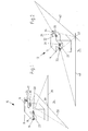
- Fig. 1
- eine erste Ausführungsform einer Vorrichtung zum Erzeugen linienförmiger optischer Markierungen,
- Fig. 2
- eine zweite Ausführungsform einer Vorrichtung zum Erzeugen linienförmiger optischer Markierungen,
- Fig. 3
- eine erste Ausführungsform einer Linse,
- Fig. 4
- eine zweite Ausführungsform einer Linse und
- Fig. 5
- eine weitere Ausführungsform einer Vorrichtung zum Erzeugen einer linienförmigen optischen Markierung.
Claims (11)
- Vorrichtung zum Abbilden einer linienförmigen optischen Markierung (36, 38, 40, 42, 60) in einen Raum umfassend ein Gehäuse (11, 13) mit das Licht entlang einer optischen Achse (15, 17, 19, 29) emittierender Lichtquelle (16, 18, 20, 22, 64) sowie eine der Lichtquelle vorgeschaltete von der optischen Achse durchsetzte das Licht sowohl reflektierende als auch durchlassende Linse (28, 30, 32, 34, 36, 38, 46, 58),
dadurch gekennzeichnet, dass die Linse (28, 30, 32, 34, 36, 46, 58) eine rinnenförmige Geometrie mit einer Längsachse (37, 49) aufweist, die quer zur optischen Achse (15, 17, 19, 29) der Lichtquelle (16, 18, 20, 22, 64) verläuft, dass die Linse einen lichtquellenseitig verlaufenden ersten Abschnitt (38, 48) aufweist und dass der erste Abschnitt Licht in Richtung der Lichtquelle bis in einen Bereich reflektiert, der sich in Abhängigkeit vom Verlauf der Längsachse der Linse unterhalb, seitlich oder oberhalb der Lichtquelle und in Bezug auf die Lichtquelle bis in lichtquellenabgewandten Bereich des Raums erstreckt. - Vorrichtung nach Anspruch 1, wobei dem Gehäuse (11, 13) eine Basisfläche (14) wie Bodenfläche des Raums zugeordnet ist,
dadurch gekennzeichnet, dass sich die Längsachse (34, 39, 59) der Linse (28, 30, 32, 34, 36, 46) entlang der Basisfläche (14) erstreckt und dass über den lichtquellenseitig verlaufenden ersten Abschnitt (38, 48) bzw. dessen Außenfläche (44, 54) Licht auf die Basisfläche in einem Bereich reflektiert ist, der in Bezug auf die Basisfläche mit einem unmittelbar unterhalb der Lichtquelle sich erstreckenden Bereich zusammenfällt. - Vorrichtung nach Anspruch 1 oder 2,
dadurch gekennzeichnet, dass die Linse (28, 30, 32, 34, 46, 58) sich aus dem lichtquellenseitig verlaufenden ersten Abschnitt (38, 48) und einem lichtquellenabgewandten zweiten Abschnitt (40, 50) zusammensetzt und dass der erste und der zweite Abschnitt jeweils zu einer Seite einer senkrecht zur optischen Achse (15, 17, 19, 21, 59) der Lichtquelle (16, 18, 20, 22) sich erstreckenden Ebene (42, 52) verlaufen und vorzugsweise unterschiedlich lang sind. - Vorrichtung nach zumindest Anspruch 3,
dadurch gekennzeichnet, dass der erste Abschnitt (38, 48) der Linse (36, 46) länger als der zweite Abschnitt (40, 50) ist. - Vorrichtung nach zumindest Anspruch 1,
dadurch gekennzeichnet, dass die eine rinnenförmige Geometrie aufweisende Linse (28, 30, 32, 34, 36, 46, 58) ein Längsabschnitt eines im Schnitt eine Kreis- oder Ellipsengeometrie aufweisenden Rohres ist. - Vorrichtung nach zumindest Anspruch 1,
dadurch gekennzeichnet, dass die die rinnenförmige Geometrie aufweisende Linse (46, 58) einen Querschnitt aufweist, der einem Abschnitt einer Parabel entspricht. - Vorrichtung nach zumindest Anspruch 1,
dadurch gekennzeichnet, dass sich zumindest der lichtquellenseitig verlaufende erste Abschnitt (38, 48) der Linse (36, 46, 56) aus Abschnitten mit voneinander abweichenden Krümmungsradien zusammensetzt. - Vorrichtung nach zumindest Anspruch 1,
dadurch gekennzeichnet, dass sich sowohl der erste Abschnitt (38, 48) als auch der zweite Abschnitt (40, 50) der Linse (36, 46, 56) aus Abschnitten mit voneinander abweichenden Krümmungsradien zusammensetzt. - Vorrichtung nach zumindest Anspruch 1,
dadurch gekennzeichnet, dass der erste Abschnitt (38) einen ersten Krümmungsradius und der zweite Abschnitt (40) der Linse (36) einen zweiten Krümmungsradius aufweist und dass der erste Krümmungsradius von dem zweiten Krümmungsradius abweicht. - Vorrichtung nach zumindest Anspruch 1,
dadurch gekennzeichnet, dass die Linse Bereiche mit voneinander abweichenden Wandstärken aufweist. - Vorrichtung nach zumindest Anspruch 1,
dadurch gekennzeichnet, dass in dem Gehäuse (11, 13) mehrere Lichtquellen (16, 18, 20, 22) mit diesen vorgeschalteten Linsen (28, 30, 32, 34) derart angeordnet sind, dass die Längsachsen (37, 49) der Linsen in einer gemeinsamen Ebene oder in parallel zueinander verlaufenden Ebenen und rechtwinklig zueinander verlaufen und sich die von den Linsen erzeugten linienförmigen optischen Markierungen (36, 38, 40, 42) unter einem rechten Winkel schneiden.
Applications Claiming Priority (4)
| Application Number | Priority Date | Filing Date | Title |
|---|---|---|---|
| DE102004015469 | 2004-03-26 | ||
| DE102004015469 | 2004-03-26 | ||
| DE202004007476U | 2004-05-10 | ||
| DE202004007476U DE202004007476U1 (de) | 2004-03-26 | 2004-05-10 | Vorrichtung zum Abbilden einer linienförmigen optischen Markierung |
Publications (2)
| Publication Number | Publication Date |
|---|---|
| EP1580526A1 true EP1580526A1 (de) | 2005-09-28 |
| EP1580526B1 EP1580526B1 (de) | 2008-01-23 |
Family
ID=34862938
Family Applications (1)
| Application Number | Title | Priority Date | Filing Date |
|---|---|---|---|
| EP05005830A Expired - Lifetime EP1580526B1 (de) | 2004-03-26 | 2005-03-17 | Vorrichtung zum Abbilden einer linienförmigen optischen Markierung |
Country Status (7)
| Country | Link |
|---|---|
| US (1) | US7252411B2 (de) |
| EP (1) | EP1580526B1 (de) |
| JP (1) | JP4942304B2 (de) |
| CN (1) | CN1673683B (de) |
| AT (1) | ATE384931T1 (de) |
| DE (2) | DE202004007476U1 (de) |
| ES (1) | ES2300890T3 (de) |
Cited By (1)
| Publication number | Priority date | Publication date | Assignee | Title |
|---|---|---|---|---|
| WO2010136236A1 (de) * | 2009-05-25 | 2010-12-02 | Robert Bosch Gmbh | Zieloptikvorrichtung |
Families Citing this family (6)
| Publication number | Priority date | Publication date | Assignee | Title |
|---|---|---|---|---|
| DE102006021421A1 (de) * | 2006-05-05 | 2007-11-15 | Stabila-Meßgeräte Gustav Ullrich GmbH | Vorrichtung und Verfahren zum Abbilden einer Markierung auf einer Begrenzung |
| DE202007015265U1 (de) | 2007-11-01 | 2009-03-12 | STABILA Messgeräte Gustav Ullrich GmbH | Anordnung zum Abbilden einer linienförmigen Markierung |
| JP5170402B2 (ja) * | 2008-03-13 | 2013-03-27 | トヨタ自動車株式会社 | 据付設備の位置決め方法 |
| US20090320302A1 (en) * | 2008-06-25 | 2009-12-31 | William Boyd | Square foot alignment device |
| DE102016205089A1 (de) * | 2016-03-29 | 2017-10-05 | Robert Bosch Gmbh | Nivelliervorrichtung mit einer pendelnden Lichterzeugungseinheit |
| EP3526543B1 (de) * | 2016-10-13 | 2024-02-28 | Stanley Black & Decker, Inc. | Elektrowerkzeug |
Citations (4)
| Publication number | Priority date | Publication date | Assignee | Title |
|---|---|---|---|---|
| US3984154A (en) * | 1973-12-21 | 1976-10-05 | Chin See L | Optical fan levelling system |
| DE10217108A1 (de) * | 2001-06-01 | 2002-12-05 | Audio Technica Machida Kk | Verfahren und Vorrichtung zum Erzeugen eines Laserstrahlenbündels für eine Lichtlinie auf Objekten |
| US6539638B1 (en) * | 2000-04-27 | 2003-04-01 | Victor Pelletier | Line projecting device |
| JP2004094123A (ja) * | 2002-09-03 | 2004-03-25 | Hitachi Koki Co Ltd | ライン発生光学素子及びそれを搭載したレーザ墨出し装置 |
Family Cites Families (24)
| Publication number | Priority date | Publication date | Assignee | Title |
|---|---|---|---|---|
| US3800278A (en) * | 1972-08-22 | 1974-03-26 | S Jaye | Brake lining wear warning gauge |
| DE2447515A1 (de) * | 1973-10-08 | 1975-04-24 | Apv Co Ltd | Drehmaschine |
| JPS5332214Y2 (de) * | 1974-04-26 | 1978-08-10 | ||
| US4188613A (en) * | 1978-05-31 | 1980-02-12 | Wong Chia Hsiang | Safety indicator for automobile braking system |
| DE3044242A1 (de) * | 1979-12-11 | 1981-09-03 | Smiths Industries Ltd., London | Anzeigesystem zur anzeige des abstandes der blaetter einer turbine zu einem bezugspunkt |
| US4536670A (en) * | 1981-12-14 | 1985-08-20 | Morganite Incorporated | Electrical brushes with wear sensors |
| DD236450B1 (de) * | 1985-04-25 | 1988-11-23 | Univ Schiller Jena | Bestrahlungseinheit fuer medizinische zwecke, insbesondere fuer anwendungen auf dem dentalgebiet |
| JPS62207885A (ja) * | 1986-03-07 | 1987-09-12 | Toshiba Corp | 高温耐熱部材 |
| GB9020474D0 (en) * | 1990-09-19 | 1990-10-31 | Hmd Seal Less Pumps Ltd | Apparatus for measuring the change of position of a rotor |
| FR2716509B1 (fr) * | 1994-01-19 | 1996-04-12 | Alliedsignal Automotive Espana | Frein à disque à sécurité accrue. |
| US5818242A (en) * | 1996-05-08 | 1998-10-06 | United Technologies Corporation | Microwave recess distance and air-path clearance sensor |
| US6580511B1 (en) * | 1997-10-28 | 2003-06-17 | Reliance Electric Technologies, Llc | System for monitoring sealing wear |
| US6260004B1 (en) * | 1997-12-31 | 2001-07-10 | Innovation Management Group, Inc. | Method and apparatus for diagnosing a pump system |
| US6434512B1 (en) * | 1998-04-02 | 2002-08-13 | Reliance Electric Technologies, Llc | Modular data collection and analysis system |
| US6502319B1 (en) * | 2000-10-04 | 2003-01-07 | Levelite Technology, Inc. | Apparatus for producing a visible line of light on a surface |
| DE50104610D1 (de) * | 2001-06-28 | 2004-12-30 | Siemens Ag | Vorrichtung zur Überwachung eines Schleifkontaktelements einer elektrischen Rotationsmaschine |
| US7062971B2 (en) * | 2001-10-01 | 2006-06-20 | Siemens Westinghouse Power Corporation | Monitoring thermal barrier coating deterioration via acoustic response to gas flow, pressure and impact |
| JP2003177020A (ja) * | 2001-12-11 | 2003-06-27 | Audio Technica Corp | レーザー墨出し器 |
| US6694629B2 (en) * | 2002-02-27 | 2004-02-24 | Trimble Navigation Llc | Laser projector for producing intersecting lines on a surface |
| US6856470B2 (en) * | 2002-08-26 | 2005-02-15 | Hitachi Koki Co., Ltd. | Rod lens and laser marking apparatus |
| JP3991821B2 (ja) * | 2002-09-03 | 2007-10-17 | 日立工機株式会社 | ライン発生光学素子及びそれを搭載したレーザ墨出し装置 |
| US7052737B2 (en) * | 2002-11-15 | 2006-05-30 | General Electric Company | Forming a monitoring deposit on a substrate |
| US7004622B2 (en) * | 2002-11-22 | 2006-02-28 | General Electric Company | Systems and methods for determining conditions of articles and methods of making such systems |
| US20040114666A1 (en) * | 2002-12-17 | 2004-06-17 | Hardwicke Canan Uslu | Temperature sensing structure, method of making the structure, gas turbine engine and method of controlling temperature |
-
2004
- 2004-05-10 DE DE202004007476U patent/DE202004007476U1/de not_active Expired - Lifetime
-
2005
- 2005-03-17 DE DE502005002605T patent/DE502005002605D1/de not_active Expired - Lifetime
- 2005-03-17 EP EP05005830A patent/EP1580526B1/de not_active Expired - Lifetime
- 2005-03-17 AT AT05005830T patent/ATE384931T1/de not_active IP Right Cessation
- 2005-03-17 US US11/081,816 patent/US7252411B2/en not_active Expired - Lifetime
- 2005-03-17 ES ES05005830T patent/ES2300890T3/es not_active Expired - Lifetime
- 2005-03-25 JP JP2005088660A patent/JP4942304B2/ja not_active Expired - Fee Related
- 2005-03-28 CN CN2005100624646A patent/CN1673683B/zh not_active Expired - Fee Related
Patent Citations (4)
| Publication number | Priority date | Publication date | Assignee | Title |
|---|---|---|---|---|
| US3984154A (en) * | 1973-12-21 | 1976-10-05 | Chin See L | Optical fan levelling system |
| US6539638B1 (en) * | 2000-04-27 | 2003-04-01 | Victor Pelletier | Line projecting device |
| DE10217108A1 (de) * | 2001-06-01 | 2002-12-05 | Audio Technica Machida Kk | Verfahren und Vorrichtung zum Erzeugen eines Laserstrahlenbündels für eine Lichtlinie auf Objekten |
| JP2004094123A (ja) * | 2002-09-03 | 2004-03-25 | Hitachi Koki Co Ltd | ライン発生光学素子及びそれを搭載したレーザ墨出し装置 |
Non-Patent Citations (1)
| Title |
|---|
| PATENT ABSTRACTS OF JAPAN vol. 2003, no. 12 5 December 2003 (2003-12-05) * |
Cited By (1)
| Publication number | Priority date | Publication date | Assignee | Title |
|---|---|---|---|---|
| WO2010136236A1 (de) * | 2009-05-25 | 2010-12-02 | Robert Bosch Gmbh | Zieloptikvorrichtung |
Also Published As
| Publication number | Publication date |
|---|---|
| US20050237748A1 (en) | 2005-10-27 |
| JP4942304B2 (ja) | 2012-05-30 |
| DE202004007476U1 (de) | 2004-09-02 |
| EP1580526B1 (de) | 2008-01-23 |
| US7252411B2 (en) | 2007-08-07 |
| CN1673683B (zh) | 2011-05-25 |
| DE502005002605D1 (de) | 2008-03-13 |
| ATE384931T1 (de) | 2008-02-15 |
| ES2300890T3 (es) | 2008-06-16 |
| CN1673683A (zh) | 2005-09-28 |
| JP2005283580A (ja) | 2005-10-13 |
Similar Documents
| Publication | Publication Date | Title |
|---|---|---|
| CH678663A5 (de) | ||
| DE10217294A1 (de) | Sensorausrichtung | |
| DE2633391A1 (de) | Optische anordnung zur erzeugung von lichtstrahlen, die genau im rechten winkel zueinander stehen | |
| DE4136002A1 (de) | Moire- konturenabbildungsvorrichtung | |
| EP1246148B1 (de) | Vorrichtung zur Überwachung eines Schutzfeldes | |
| EP2056067B1 (de) | Anordnung zum Abbilden einer linienförmigen Markierung | |
| EP1580526B1 (de) | Vorrichtung zum Abbilden einer linienförmigen optischen Markierung | |
| DE10317958B4 (de) | Vorrichtung zum Erzeugen und Projizieren von Lichtmarken | |
| EP3695245A1 (de) | Optische vorrichtung für eine abstandsmessvorrichtung nach dem lidar-prinzip | |
| DE3446354C2 (de) | ||
| DE2200092C3 (de) | Optische Lesevorrichtung zur Abtastung von Codemarken auf Gegenständen | |
| DE102004028366B4 (de) | Licht-Zielsystem | |
| DE3708647C2 (de) | ||
| DE10135828A1 (de) | Laserbeleuchtungsvorrichtung zum Beleuchten eines streifen- oder linienförmigen Bereichs | |
| WO2013068168A1 (de) | Laser-leuchtstoff-vorrichtung mit laserarray | |
| DE102004011911A1 (de) | Sendeelement für Lichtschranken, Lichtgitter und dergleichen | |
| DE102016121438A1 (de) | Scheinwerfer, insbesondere Scheinwerfer eines Kraftfahrzeugs | |
| DE102017209645B4 (de) | Mikromechanische Lichtumlenkvorrichtung, Verfahren zur Umlenkung von Licht mittels einer mikromechanischen Lichtumlenkvorrichtung und Lichtsendevorrichtung | |
| DE10062784A1 (de) | Verfahren zur optischen Inspektion von transparenten Körpern | |
| DE102022000743B3 (de) | Optische Einrichtung zur Ablenkung und Fokussierung von Laserstrahlung zur Lasermaterialbearbeitung und Verwendung zweier miteinander verbundener und angetrieben rotierender Polygonspiegel, eines Galvanometerscanners und einer Fokussieroptik | |
| WO2019081449A1 (de) | Lichtaustrittsvorrichtung für einen laserscanner | |
| WO2010085940A1 (de) | Vorrichtung und verfahren zur berührungslosen messung eines abstands und/oder eines profils | |
| DE2127013C3 (de) | Reflexionslichtschranke | |
| DE19722561C2 (de) | Optische Anordnung zur Abbildung von Objekten oder Strahlquellen und Verwendungen einer solchen optischen Anordnung | |
| DE700698C (de) | Vorrichtung zur Beleuchtung der gekruemmten spiegeoptischen Abbildung |
Legal Events
| Date | Code | Title | Description |
|---|---|---|---|
| PUAI | Public reference made under article 153(3) epc to a published international application that has entered the european phase |
Free format text: ORIGINAL CODE: 0009012 |
|
| AK | Designated contracting states |
Kind code of ref document: A1 Designated state(s): AT BE BG CH CY CZ DE DK EE ES FI FR GB GR HU IE IS IT LI LT LU MC NL PL PT RO SE SI SK TR |
|
| AX | Request for extension of the european patent |
Extension state: AL BA HR LV MK YU |
|
| 17P | Request for examination filed |
Effective date: 20060317 |
|
| AKX | Designation fees paid |
Designated state(s): AT BE BG CH CY CZ DE DK EE ES FI FR GB GR HU IE IS IT LI LT LU MC NL PL PT RO SE SI SK TR |
|
| 17Q | First examination report despatched |
Effective date: 20061219 |
|
| GRAP | Despatch of communication of intention to grant a patent |
Free format text: ORIGINAL CODE: EPIDOSNIGR1 |
|
| GRAS | Grant fee paid |
Free format text: ORIGINAL CODE: EPIDOSNIGR3 |
|
| GRAA | (expected) grant |
Free format text: ORIGINAL CODE: 0009210 |
|
| AK | Designated contracting states |
Kind code of ref document: B1 Designated state(s): AT BE BG CH CY CZ DE DK EE ES FI FR GB GR HU IE IS IT LI LT LU MC NL PL PT RO SE SI SK TR |
|
| REG | Reference to a national code |
Ref country code: GB Ref legal event code: FG4D Free format text: NOT ENGLISH |
|
| RIN1 | Information on inventor provided before grant (corrected) |
Inventor name: KALLABIS, GABRIEL Inventor name: BUSAM, DANIEL |
|
| REG | Reference to a national code |
Ref country code: CH Ref legal event code: EP |
|
| REG | Reference to a national code |
Ref country code: IE Ref legal event code: FG4D Free format text: LANGUAGE OF EP DOCUMENT: GERMAN |
|
| REF | Corresponds to: |
Ref document number: 502005002605 Country of ref document: DE Date of ref document: 20080313 Kind code of ref document: P |
|
| REG | Reference to a national code |
Ref country code: ES Ref legal event code: FG2A Ref document number: 2300890 Country of ref document: ES Kind code of ref document: T3 |
|
| NLV1 | Nl: lapsed or annulled due to failure to fulfill the requirements of art. 29p and 29m of the patents act | ||
| PG25 | Lapsed in a contracting state [announced via postgrant information from national office to epo] |
Ref country code: IS Free format text: LAPSE BECAUSE OF FAILURE TO SUBMIT A TRANSLATION OF THE DESCRIPTION OR TO PAY THE FEE WITHIN THE PRESCRIBED TIME-LIMIT Effective date: 20080523 Ref country code: FI Free format text: LAPSE BECAUSE OF FAILURE TO SUBMIT A TRANSLATION OF THE DESCRIPTION OR TO PAY THE FEE WITHIN THE PRESCRIBED TIME-LIMIT Effective date: 20080123 |
|
| PG25 | Lapsed in a contracting state [announced via postgrant information from national office to epo] |
Ref country code: BG Free format text: LAPSE BECAUSE OF FAILURE TO SUBMIT A TRANSLATION OF THE DESCRIPTION OR TO PAY THE FEE WITHIN THE PRESCRIBED TIME-LIMIT Effective date: 20080423 |
|
| ET | Fr: translation filed | ||
| BERE | Be: lapsed |
Owner name: STABILA MESSGERATE GUSTAV ULLRICH G.M.B.H. Effective date: 20080331 |
|
| PG25 | Lapsed in a contracting state [announced via postgrant information from national office to epo] |
Ref country code: PL Free format text: LAPSE BECAUSE OF FAILURE TO SUBMIT A TRANSLATION OF THE DESCRIPTION OR TO PAY THE FEE WITHIN THE PRESCRIBED TIME-LIMIT Effective date: 20080123 Ref country code: PT Free format text: LAPSE BECAUSE OF FAILURE TO SUBMIT A TRANSLATION OF THE DESCRIPTION OR TO PAY THE FEE WITHIN THE PRESCRIBED TIME-LIMIT Effective date: 20080623 Ref country code: SI Free format text: LAPSE BECAUSE OF FAILURE TO SUBMIT A TRANSLATION OF THE DESCRIPTION OR TO PAY THE FEE WITHIN THE PRESCRIBED TIME-LIMIT Effective date: 20080123 |
|
| REG | Reference to a national code |
Ref country code: IE Ref legal event code: FD4D |
|
| PG25 | Lapsed in a contracting state [announced via postgrant information from national office to epo] |
Ref country code: SK Free format text: LAPSE BECAUSE OF FAILURE TO SUBMIT A TRANSLATION OF THE DESCRIPTION OR TO PAY THE FEE WITHIN THE PRESCRIBED TIME-LIMIT Effective date: 20080123 Ref country code: NL Free format text: LAPSE BECAUSE OF FAILURE TO SUBMIT A TRANSLATION OF THE DESCRIPTION OR TO PAY THE FEE WITHIN THE PRESCRIBED TIME-LIMIT Effective date: 20080123 Ref country code: MC Free format text: LAPSE BECAUSE OF NON-PAYMENT OF DUE FEES Effective date: 20080331 Ref country code: IE Free format text: LAPSE BECAUSE OF FAILURE TO SUBMIT A TRANSLATION OF THE DESCRIPTION OR TO PAY THE FEE WITHIN THE PRESCRIBED TIME-LIMIT Effective date: 20080123 Ref country code: CZ Free format text: LAPSE BECAUSE OF FAILURE TO SUBMIT A TRANSLATION OF THE DESCRIPTION OR TO PAY THE FEE WITHIN THE PRESCRIBED TIME-LIMIT Effective date: 20080123 Ref country code: DK Free format text: LAPSE BECAUSE OF FAILURE TO SUBMIT A TRANSLATION OF THE DESCRIPTION OR TO PAY THE FEE WITHIN THE PRESCRIBED TIME-LIMIT Effective date: 20080123 Ref country code: SE Free format text: LAPSE BECAUSE OF FAILURE TO SUBMIT A TRANSLATION OF THE DESCRIPTION OR TO PAY THE FEE WITHIN THE PRESCRIBED TIME-LIMIT Effective date: 20080423 |
|
| PG25 | Lapsed in a contracting state [announced via postgrant information from national office to epo] |
Ref country code: RO Free format text: LAPSE BECAUSE OF FAILURE TO SUBMIT A TRANSLATION OF THE DESCRIPTION OR TO PAY THE FEE WITHIN THE PRESCRIBED TIME-LIMIT Effective date: 20080123 |
|
| PLBE | No opposition filed within time limit |
Free format text: ORIGINAL CODE: 0009261 |
|
| STAA | Information on the status of an ep patent application or granted ep patent |
Free format text: STATUS: NO OPPOSITION FILED WITHIN TIME LIMIT |
|
| 26N | No opposition filed |
Effective date: 20081024 |
|
| PG25 | Lapsed in a contracting state [announced via postgrant information from national office to epo] |
Ref country code: EE Free format text: LAPSE BECAUSE OF FAILURE TO SUBMIT A TRANSLATION OF THE DESCRIPTION OR TO PAY THE FEE WITHIN THE PRESCRIBED TIME-LIMIT Effective date: 20080123 Ref country code: LT Free format text: LAPSE BECAUSE OF FAILURE TO SUBMIT A TRANSLATION OF THE DESCRIPTION OR TO PAY THE FEE WITHIN THE PRESCRIBED TIME-LIMIT Effective date: 20080123 |
|
| PG25 | Lapsed in a contracting state [announced via postgrant information from national office to epo] |
Ref country code: BE Free format text: LAPSE BECAUSE OF NON-PAYMENT OF DUE FEES Effective date: 20080331 |
|
| PG25 | Lapsed in a contracting state [announced via postgrant information from national office to epo] |
Ref country code: CY Free format text: LAPSE BECAUSE OF FAILURE TO SUBMIT A TRANSLATION OF THE DESCRIPTION OR TO PAY THE FEE WITHIN THE PRESCRIBED TIME-LIMIT Effective date: 20080123 |
|
| PG25 | Lapsed in a contracting state [announced via postgrant information from national office to epo] |
Ref country code: AT Free format text: LAPSE BECAUSE OF NON-PAYMENT OF DUE FEES Effective date: 20080317 |
|
| REG | Reference to a national code |
Ref country code: CH Ref legal event code: PL |
|
| PG25 | Lapsed in a contracting state [announced via postgrant information from national office to epo] |
Ref country code: CH Free format text: LAPSE BECAUSE OF NON-PAYMENT OF DUE FEES Effective date: 20090331 Ref country code: LI Free format text: LAPSE BECAUSE OF NON-PAYMENT OF DUE FEES Effective date: 20090331 |
|
| PG25 | Lapsed in a contracting state [announced via postgrant information from national office to epo] |
Ref country code: LU Free format text: LAPSE BECAUSE OF NON-PAYMENT OF DUE FEES Effective date: 20080317 Ref country code: HU Free format text: LAPSE BECAUSE OF FAILURE TO SUBMIT A TRANSLATION OF THE DESCRIPTION OR TO PAY THE FEE WITHIN THE PRESCRIBED TIME-LIMIT Effective date: 20080724 |
|
| PG25 | Lapsed in a contracting state [announced via postgrant information from national office to epo] |
Ref country code: TR Free format text: LAPSE BECAUSE OF FAILURE TO SUBMIT A TRANSLATION OF THE DESCRIPTION OR TO PAY THE FEE WITHIN THE PRESCRIBED TIME-LIMIT Effective date: 20080123 |
|
| PG25 | Lapsed in a contracting state [announced via postgrant information from national office to epo] |
Ref country code: GR Free format text: LAPSE BECAUSE OF FAILURE TO SUBMIT A TRANSLATION OF THE DESCRIPTION OR TO PAY THE FEE WITHIN THE PRESCRIBED TIME-LIMIT Effective date: 20080424 |
|
| REG | Reference to a national code |
Ref country code: FR Ref legal event code: PLFP Year of fee payment: 12 |
|
| REG | Reference to a national code |
Ref country code: FR Ref legal event code: PLFP Year of fee payment: 13 |
|
| REG | Reference to a national code |
Ref country code: FR Ref legal event code: PLFP Year of fee payment: 14 |
|
| PGFP | Annual fee paid to national office [announced via postgrant information from national office to epo] |
Ref country code: FR Payment date: 20200319 Year of fee payment: 16 |
|
| PGFP | Annual fee paid to national office [announced via postgrant information from national office to epo] |
Ref country code: ES Payment date: 20200522 Year of fee payment: 16 |
|
| PG25 | Lapsed in a contracting state [announced via postgrant information from national office to epo] |
Ref country code: FR Free format text: LAPSE BECAUSE OF NON-PAYMENT OF DUE FEES Effective date: 20210331 |
|
| PGFP | Annual fee paid to national office [announced via postgrant information from national office to epo] |
Ref country code: GB Payment date: 20220321 Year of fee payment: 18 |
|
| REG | Reference to a national code |
Ref country code: ES Ref legal event code: FD2A Effective date: 20220523 |
|
| PGFP | Annual fee paid to national office [announced via postgrant information from national office to epo] |
Ref country code: IT Payment date: 20220322 Year of fee payment: 18 |
|
| PG25 | Lapsed in a contracting state [announced via postgrant information from national office to epo] |
Ref country code: ES Free format text: LAPSE BECAUSE OF NON-PAYMENT OF DUE FEES Effective date: 20210318 |
|
| PGFP | Annual fee paid to national office [announced via postgrant information from national office to epo] |
Ref country code: DE Payment date: 20230328 Year of fee payment: 19 |
|
| P01 | Opt-out of the competence of the unified patent court (upc) registered |
Effective date: 20230528 |
|
| GBPC | Gb: european patent ceased through non-payment of renewal fee |
Effective date: 20230317 |
|
| PG25 | Lapsed in a contracting state [announced via postgrant information from national office to epo] |
Ref country code: GB Free format text: LAPSE BECAUSE OF NON-PAYMENT OF DUE FEES Effective date: 20230317 |
|
| PG25 | Lapsed in a contracting state [announced via postgrant information from national office to epo] |
Ref country code: GB Free format text: LAPSE BECAUSE OF NON-PAYMENT OF DUE FEES Effective date: 20230317 |
|
| PG25 | Lapsed in a contracting state [announced via postgrant information from national office to epo] |
Ref country code: IT Free format text: LAPSE BECAUSE OF NON-PAYMENT OF DUE FEES Effective date: 20230317 |
|
| REG | Reference to a national code |
Ref country code: DE Ref legal event code: R119 Ref document number: 502005002605 Country of ref document: DE |
|
| PG25 | Lapsed in a contracting state [announced via postgrant information from national office to epo] |
Ref country code: DE Free format text: LAPSE BECAUSE OF NON-PAYMENT OF DUE FEES Effective date: 20241001 |
|
| PG25 | Lapsed in a contracting state [announced via postgrant information from national office to epo] |
Ref country code: DE Free format text: LAPSE BECAUSE OF NON-PAYMENT OF DUE FEES Effective date: 20241001 |