EP1580535A2 - Procédé et appareil de détection d'un déplacement relatif entre un capteur et un corps avec une structure de surface - Google Patents
Procédé et appareil de détection d'un déplacement relatif entre un capteur et un corps avec une structure de surface Download PDFInfo
- Publication number
- EP1580535A2 EP1580535A2 EP05006650A EP05006650A EP1580535A2 EP 1580535 A2 EP1580535 A2 EP 1580535A2 EP 05006650 A EP05006650 A EP 05006650A EP 05006650 A EP05006650 A EP 05006650A EP 1580535 A2 EP1580535 A2 EP 1580535A2
- Authority
- EP
- European Patent Office
- Prior art keywords
- movement
- detector
- surface structure
- detected
- speed
- Prior art date
- Legal status (The legal status is an assumption and is not a legal conclusion. Google has not performed a legal analysis and makes no representation as to the accuracy of the status listed.)
- Withdrawn
Links
Images

Classifications
-
- G—PHYSICS
- G01—MEASURING; TESTING
- G01D—MEASURING NOT SPECIALLY ADAPTED FOR A SPECIFIC VARIABLE; ARRANGEMENTS FOR MEASURING TWO OR MORE VARIABLES NOT COVERED IN A SINGLE OTHER SUBCLASS; TARIFF METERING APPARATUS; MEASURING OR TESTING NOT OTHERWISE PROVIDED FOR
- G01D5/00—Mechanical means for transferring the output of a sensing member; Means for converting the output of a sensing member to another variable where the form or nature of the sensing member does not constrain the means for converting; Transducers not specially adapted for a specific variable
- G01D5/26—Mechanical means for transferring the output of a sensing member; Means for converting the output of a sensing member to another variable where the form or nature of the sensing member does not constrain the means for converting; Transducers not specially adapted for a specific variable characterised by optical transfer means, i.e. using infrared, visible, or ultraviolet light
Definitions
- the present invention relates to a method and an apparatus Detecting a relative movement between a detector and a body with a Surface structure, wherein the relative movement at a fixed detector by a Movement of the body, in the case of a body fixed by a movement of the detector or by moving both the detector and the body.
- the Angle encoder includes a light source, a light detector and a perforated disk.
- the Light detector detects the light of the light source, wherein the light of the light source the rotating perforated disc is interrupted again and again.
- the light detector generates a square wave signal.
- the pulse length corresponds to the exposure time of the light detector.
- An evaluation system receives the signal of the light detector and determines from this the position of the rotating body.
- the disadvantage of this system is that it is relatively expensive Components such as e.g. the light detector, the light source and the evaluation system connected is. This results in a corresponding complexity and error rate of the Angle encoder.
- the resolving power becomes the orientation determined by the size, the location and the number of holes in the perforated disc. Around To obtain a higher resolution accuracy in determining the position must, for. B. the Perforated disk to be replaced. This is associated with a relatively high cost because the machine, in this example the balancing machine, first has to be disassembled.
- a square wave signal is generated, which is a measure of is the distance traveled by the workpiece.
- Such pulser can the determine the distance covered in one direction only, and for a determination an angle at which the workpiece moves to the said direction must be be provided further detector.
- the object of the invention is therefore a method and an apparatus for To provide a relative movement between a detector and a Detecting body with a surface structure without resorting to mechanical means to have to fall back.
- the inventive method for detection a relative movement between a detector and a body with a Surface structure in the form of a path and / or an angle of relative movement characterized in that the movement of the surface structure of the body by means of a camera provided in the detector is detected that from the sequence of the detected Surface structures the direction of movement and the speed of movement of the Relative movement is determined, and that the distance traveled from the Movement direction and the movement speed is determined.
- An advantageous embodiment of the method according to the invention is characterized characterized in that the distance traveled in a defined number of increments, for example, 360 increments, is divided. With this incrementing is a direct Conversion into the angular unit degrees possible. A conversion into each other suitable angle unit is also possible.
- An advantageous embodiment of the method according to the invention wherein the moving bodies are a body moving in a plane and the detector is stationary is arranged, is characterized in that the surface structure at one of the rotating body provided scanning surface is detected, and that from the Direction of movement and the speed of movement of the path traveled Body is determined.
- An advantageous embodiment of the method according to the invention wherein the body is arranged stationary and the detector is moved relative to the body, is characterized in that the surface structure is detected on a scanning surface provided on the body, and that the distance traveled is determined from the direction of movement and the speed of movement of the relative movement.
- An advantageous embodiment of the method according to the invention is characterized characterized in that a reference mark in a predetermined relation to the body is provided.
- the inventive device for detecting a relative movement between a detector and a body with a Surface structure in the form of a path and / or an angle of relative movement characterized by a camera provided in the detector which controls the movement of the camera Surface structure of the body detected, and by a processor device, made of the Sequence of the detected surface structures the direction of movement and the Movement speed of the relative movement and from this the distance covered by the Relative movement determined.
- An advantageous embodiment of the device according to the invention wherein the moving bodies a rotationally symmetric, rotating body and the Detector is stationary, is characterized in that the camera designed is to provide the surface structure at one of the rotating body Scanning area to capture, and that the processor is designed to be out of the Direction of movement and the speed of movement the path covered determine and convert it into a traversed angle.
- An advantageous embodiment of the device according to the invention wherein the moving bodies are a body moving in a plane and the detector is stationary, is characterized in that the camera is designed to the surface structure on a provided on the rotating body scanning surface to capture, and the processor is configured to move from the direction of movement and the Movement speed to determine the distance traveled by the body.
- An advantageous embodiment of the device according to the invention, wherein the Body is stationary and the detector is moved relative to the body is characterized in that the surface structure on one of the body provided scanning surface is detected, and that the processor is configured to the Direction of movement and the speed of movement of the relative movement determine the distance traveled.
- An advantageous embodiment of the device according to the invention is characterized characterized in that the reference feature is a mark or a characteristic Structure is.
- An advantageous embodiment of the device according to the invention is characterized characterized in that the reference feature is a notch or a dash.
- An advantageous embodiment of the device according to the invention is characterized characterized in that the reference feature is a separate the reference mark, and that a separate sensor for detecting the reference feature is provided.
- An advantageous embodiment of the device according to the invention is characterized characterized in that the sensor is a photodiode.
- the sensor is a photodiode.
- a photodiode can be to Detection of the reference mark the production cost of the device of the present Significantly reduce the invention.
- An advantageous embodiment of the device according to the invention is characterized by a light source in the detector, with which the surface structure the body is illuminated.
- An advantageous embodiment of the device according to the invention is characterized characterized in that the light source is a light-emitting diode (LED).
- LED light-emitting diode
- An advantageous embodiment of the device according to the invention is characterized characterized in that the camera is a camera chip.
- a camera chip offers the advantage the detailed image capture with a high sampling rate. This can be a high Achieve resolution in determining the path or angle.
- An advantageous embodiment of the device according to the invention is characterized characterized in that the camera chip and the processor are integrated on a chip.
- the invention further relates to a balancing machine with a device for Detecting the relative movement between a detector and a body with a Surface structure of the type described above, wherein the angular position of a balancing rotor is determined.
- the invention further relates to an NC machine with a device for Detecting the relative movement between a detector and a body with a Surface structure of the type described above, wherein the distance of one in the NC machine is determined to moving workpiece.
- the invention further relates to a distance measuring device for the determination of Distances on a map or map with a device for capturing the Relative movement between a detector and a body with a Surface structure of the type described above, wherein the processor has a computing function and input means for inputting a number information are provided to to convert the recorded path to a scale via the input means is to enter.
- Figure 1 shows the basic structure of the device of the present invention the example of a rotationally symmetrical body 2 in sectional view.
- a detector 5 is arranged, which is a light source 4, for example a light-emitting Diode, and a camera 6, for example, a camera chip has.
- the detector 5 detects continuously the surface structure of the body 2.
- the camera 6 For processing the data of the detected surface structure, the camera 6 with connected to a processor. There is a program on the processor that comes from the As a result of the detected surface structure, the direction of movement and the speed of the moving body 2 and, as a result, the coordinates of the Moving body 2 determines that follow from the relative movement. Furthermore is located in the axial end of the body 2, a reference mark 8, whose task and Function will be described in more detail in Figure 2.
- FIG. 2 shows a side view of a rotationally symmetrical body 12 on which a reference mark 14 and a sensor 16 for detecting the reference mark 14 is provided.
- the reference mark 14 which in FIG 2 is radially attached to the body 12, detected by the sensor 16.
- the Reference mark 14 on the rotationally symmetrical body 12 is to be detected Distance, in this case the circumference of the rotationally symmetric body 12, with a Start and end point defined in the form of reference mark 14.
- a relative angular position of determine the moving body can be in a rotationally symmetrical body with the device and the method of the present invention.
- a rotation angle with the the light sensor 6 of Figure 1 detected and marked by the reference mark 8 and 14 respectively Distance divided into a defined number of increments.
- the recorded route can be divided into 360 increments, which gives the degree system 360 degrees for corresponds to the full circle. In addition to the division into 360 increments are all the others suitable increments possible.
- the increment serves to, the Position for unbalance compensation during manual or automatic screwing of rotationally symmetrical bodies to compensate for the unbalance.
- the number of wings or the radiator wings detected and for the imbalance correction on the respective wing (component) are screwed.
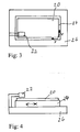
- FIGS. 3 and 4 Alternatively to the rotationally symmetrical geometry of the movable body 2 and 12 show the FIGS. 3 and 4 a schematic plan view and a side view of a Workpiece 20 in an NC machine (numerically controlled machine tool) and the Detector 22.
- the moving body in one or more Moving planes, wherein the movement of a workpiece carriage 24 with respect to a Machine base 26 in a plane x - y is shown schematically.
- the detector 22 can either directly with the workpiece 20 or with a scanning surface on the NC machine cooperate, wherein the scanning then a defined position to the workpiece 20th Has.
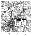
- Fig. 5 is a schematic plan view of a map 30 with a movable range finder 32 for determining distances on a map or a map with a device for detecting the relative movement between a detector and a body having a surface structure as described above Art, wherein the processor in the detector in the distance measuring a Computing function and input means 34 for inputting a number information are provided to convert the detected path to a scale that exceeds the Input means is input.
- the distance measuring device 32 also has a start-stop button 36 with which the beginning and the end of the distance measurement are entered.
- a Reference arrow 38 serves the distance measuring device 32 on the route to be measured to lead along. The measurement results can be displayed on a display 40.
- a photoelectric cell serves as a power supply of the distance measuring device 32.
Landscapes
- Physics & Mathematics (AREA)
- General Physics & Mathematics (AREA)
- Length Measuring Devices By Optical Means (AREA)
- Length Measuring Devices With Unspecified Measuring Means (AREA)
Applications Claiming Priority (2)
| Application Number | Priority Date | Filing Date | Title |
|---|---|---|---|
| DE102004014994 | 2004-03-26 | ||
| DE200410014994 DE102004014994A1 (de) | 2004-03-26 | 2004-03-26 | Verfahren und Vorrichtung zur Erfassung einer Relativbewegung zwischen einem Detektor und einem Körpers mit einer Oberflächenstruktur |
Publications (2)
| Publication Number | Publication Date |
|---|---|
| EP1580535A2 true EP1580535A2 (fr) | 2005-09-28 |
| EP1580535A3 EP1580535A3 (fr) | 2006-10-18 |
Family
ID=34854076
Family Applications (1)
| Application Number | Title | Priority Date | Filing Date |
|---|---|---|---|
| EP05006650A Withdrawn EP1580535A3 (fr) | 2004-03-26 | 2005-03-24 | Procédé et appareil de détection d'un déplacement relatif entre un capteur et un corps avec une structure de surface |
Country Status (2)
| Country | Link |
|---|---|
| EP (1) | EP1580535A3 (fr) |
| DE (1) | DE102004014994A1 (fr) |
Families Citing this family (1)
| Publication number | Priority date | Publication date | Assignee | Title |
|---|---|---|---|---|
| DE102006030810B4 (de) * | 2006-06-30 | 2010-06-10 | Siemens Ag | Anordnung zur Erfassung der Bewegung von flachen Sendungen |
Family Cites Families (3)
| Publication number | Priority date | Publication date | Assignee | Title |
|---|---|---|---|---|
| US4891767A (en) * | 1988-06-02 | 1990-01-02 | Combustion Engineering, Inc. | Machine vision system for position sensing |
| US5578813A (en) * | 1995-03-02 | 1996-11-26 | Allen; Ross R. | Freehand image scanning device which compensates for non-linear movement |
| US6246050B1 (en) * | 1999-03-08 | 2001-06-12 | Hewlett-Packard Company | Optical encoders using non-patterned targets |
-
2004
- 2004-03-26 DE DE200410014994 patent/DE102004014994A1/de not_active Withdrawn
-
2005
- 2005-03-24 EP EP05006650A patent/EP1580535A3/fr not_active Withdrawn
Also Published As
| Publication number | Publication date |
|---|---|
| DE102004014994A1 (de) | 2005-10-13 |
| EP1580535A3 (fr) | 2006-10-18 |
Similar Documents
| Publication | Publication Date | Title |
|---|---|---|
| DE69925582T2 (de) | Vorrichtung und verfahren zum optischen messen der oberflächenkontur eines objekts | |
| DE102015205738A1 (de) | Bewegungsmesssystem einer Maschine und Verfahren zum Betreiben des Bewegungsmesssystems | |
| DE102017211327A1 (de) | Bildmessgerät | |
| DE19828498C2 (de) | Verfahren zum Messen von Unwuchten rotierender Körper und Vorrichtung zur Durchführung des Verfahrens | |
| DE102017211328A1 (de) | Bildmessgerät | |
| WO2012079734A1 (fr) | Dispositif de réglage et/ou de mesure | |
| DE68906669T2 (de) | Messsystem fuer eine werkzeugeinstellung in einer werkzeugmaschine. | |
| DE2907648C2 (fr) | ||
| WO2007112872A1 (fr) | Procede et dispositif de determination et de mesure d'ecarts de forme et d'ondulations sur des pieces a symetrie de rotation | |
| DE4116313C2 (de) | Verfahren und Vorrichtung zur Messung der Elastomechanik von Sedimenten aus Suspensionen und Emulsionen | |
| DE102005007533A1 (de) | Objektträgervorrichtung | |
| EP1580535A2 (fr) | Procédé et appareil de détection d'un déplacement relatif entre un capteur et un corps avec une structure de surface | |
| DE3417016C1 (de) | Verfahren zur Ermittlung der Lage und Geschwindigkeit von Objekten | |
| EP3760981B1 (fr) | Dispositif de mesure d'angle et procédé de fonctionnement d'un dispositif de mesure d'angle | |
| EP4514562B1 (fr) | Procédé pour déterminer des défauts géométriques, en particulier statiques, d'une machine laser pour la découpe, la gravure, le marquage d'une pièce et/ou l'inscription sur une pièce et procédé pour déterminer la position ou l'emplacement du point central d'un détecteur sur l'élément détecteur ainsi que segment d'étalonnage et machine laser à cet effet | |
| CN207881736U (zh) | 一种编码器测试平台 | |
| DE102021118105B4 (de) | Verfahren zur Messung der rotorwinkelbezogenen Aufweitung eines drehenden Rotors unter Fliehkraftbelastung | |
| DE102010001833A1 (de) | Formmessvorrichtung, Formmessverfahren und -programm | |
| EP0514726A1 (fr) | Méthode pour considérer, pendant l'équilibrage, la déviation de position des manetons de la bielle d'un vilebrequin et dispositif pour cela | |
| CN222231558U (zh) | 测量装置 | |
| Loktev et al. | Measuring instruments for shafts. | |
| DE10146713A1 (de) | Verfahren zur Vermessung von Großbauteilen, insbesondere Wagenkästen von Schienenfahrzeugen | |
| DE202024107385U1 (de) | Werkzeugmaschineneinheit mit Prüfung von Lagerbelastungen der Spindel im Betrieb | |
| DD255583A1 (de) | Verfahren und einrichtung zur automatisierten pruefung der anzeigeabweichung von buegelmessschrauben | |
| DD228050A1 (de) | Verfahren und vorrichtung zum genauen erfassen von teilungen |
Legal Events
| Date | Code | Title | Description |
|---|---|---|---|
| PUAI | Public reference made under article 153(3) epc to a published international application that has entered the european phase |
Free format text: ORIGINAL CODE: 0009012 |
|
| AK | Designated contracting states |
Kind code of ref document: A2 Designated state(s): AT BE BG CH CY CZ DE DK EE ES FI FR GB GR HU IE IS IT LI LT LU MC NL PL PT RO SE SI SK TR |
|
| AX | Request for extension of the european patent |
Extension state: AL BA HR LV MK YU |
|
| PUAL | Search report despatched |
Free format text: ORIGINAL CODE: 0009013 |
|
| AK | Designated contracting states |
Kind code of ref document: A3 Designated state(s): AT BE BG CH CY CZ DE DK EE ES FI FR GB GR HU IE IS IT LI LT LU MC NL PL PT RO SE SI SK TR |
|
| AX | Request for extension of the european patent |
Extension state: AL BA HR LV MK YU |
|
| AKX | Designation fees paid | ||
| STAA | Information on the status of an ep patent application or granted ep patent |
Free format text: STATUS: THE APPLICATION IS DEEMED TO BE WITHDRAWN |
|
| 18D | Application deemed to be withdrawn |
Effective date: 20070419 |
|
| REG | Reference to a national code |
Ref country code: DE Ref legal event code: 8566 |