EP1580552A1 - Mikrofluidisches Analysesystem mit Positionselektroden - Google Patents
Mikrofluidisches Analysesystem mit Positionselektroden Download PDFInfo
- Publication number
- EP1580552A1 EP1580552A1 EP05251850A EP05251850A EP1580552A1 EP 1580552 A1 EP1580552 A1 EP 1580552A1 EP 05251850 A EP05251850 A EP 05251850A EP 05251850 A EP05251850 A EP 05251850A EP 1580552 A1 EP1580552 A1 EP 1580552A1
- Authority
- EP
- European Patent Office
- Prior art keywords
- micro
- channel
- electrode
- position electrode
- liquid sample
- Prior art date
- Legal status (The legal status is an assumption and is not a legal conclusion. Google has not performed a legal analysis and makes no representation as to the accuracy of the status listed.)
- Withdrawn
Links
- 239000007788 liquid Substances 0.000 claims abstract description 126
- 239000012491 analyte Substances 0.000 claims abstract description 80
- 238000004891 communication Methods 0.000 claims abstract description 30
- 238000004458 analytical method Methods 0.000 claims abstract description 13
- 238000012544 monitoring process Methods 0.000 claims abstract description 11
- 230000001419 dependent effect Effects 0.000 claims abstract description 7
- WYTGDNHDOZPMIW-RCBQFDQVSA-N alstonine Natural products C1=CC2=C3C=CC=CC3=NC2=C2N1C[C@H]1[C@H](C)OC=C(C(=O)OC)[C@H]1C2 WYTGDNHDOZPMIW-RCBQFDQVSA-N 0.000 claims 1
- WQZGKKKJIJFFOK-GASJEMHNSA-N Glucose Natural products OC[C@H]1OC(O)[C@H](O)[C@@H](O)[C@@H]1O WQZGKKKJIJFFOK-GASJEMHNSA-N 0.000 abstract description 18
- 239000008103 glucose Substances 0.000 abstract description 18
- 238000010586 diagram Methods 0.000 description 32
- 210000003722 extracellular fluid Anatomy 0.000 description 20
- 239000012528 membrane Substances 0.000 description 13
- 238000005259 measurement Methods 0.000 description 12
- 238000005070 sampling Methods 0.000 description 10
- 238000001514 detection method Methods 0.000 description 7
- 230000035515 penetration Effects 0.000 description 6
- 210000004369 blood Anatomy 0.000 description 5
- 239000008280 blood Substances 0.000 description 5
- 238000000034 method Methods 0.000 description 5
- 230000009286 beneficial effect Effects 0.000 description 4
- 230000008901 benefit Effects 0.000 description 4
- 230000008859 change Effects 0.000 description 4
- 239000004020 conductor Substances 0.000 description 4
- 230000007423 decrease Effects 0.000 description 4
- BQCADISMDOOEFD-UHFFFAOYSA-N Silver Chemical compound [Ag] BQCADISMDOOEFD-UHFFFAOYSA-N 0.000 description 3
- 238000004519 manufacturing process Methods 0.000 description 3
- 229910052709 silver Inorganic materials 0.000 description 3
- 239000004332 silver Substances 0.000 description 3
- OKTJSMMVPCPJKN-UHFFFAOYSA-N Carbon Chemical compound [C] OKTJSMMVPCPJKN-UHFFFAOYSA-N 0.000 description 2
- KDLHZDBZIXYQEI-UHFFFAOYSA-N Palladium Chemical compound [Pd] KDLHZDBZIXYQEI-UHFFFAOYSA-N 0.000 description 2
- 229910021607 Silver chloride Inorganic materials 0.000 description 2
- 230000004888 barrier function Effects 0.000 description 2
- 239000000872 buffer Substances 0.000 description 2
- 229910052799 carbon Inorganic materials 0.000 description 2
- 239000003153 chemical reaction reagent Substances 0.000 description 2
- 238000000354 decomposition reaction Methods 0.000 description 2
- 238000005868 electrolysis reaction Methods 0.000 description 2
- 238000000605 extraction Methods 0.000 description 2
- 239000012530 fluid Substances 0.000 description 2
- 230000002209 hydrophobic effect Effects 0.000 description 2
- 239000011810 insulating material Substances 0.000 description 2
- 230000007246 mechanism Effects 0.000 description 2
- 229910000510 noble metal Inorganic materials 0.000 description 2
- 230000010363 phase shift Effects 0.000 description 2
- 210000002381 plasma Anatomy 0.000 description 2
- BASFCYQUMIYNBI-UHFFFAOYSA-N platinum Chemical compound [Pt] BASFCYQUMIYNBI-UHFFFAOYSA-N 0.000 description 2
- 238000007650 screen-printing Methods 0.000 description 2
- 210000002966 serum Anatomy 0.000 description 2
- HKZLPVFGJNLROG-UHFFFAOYSA-M silver monochloride Chemical compound [Cl-].[Ag+] HKZLPVFGJNLROG-UHFFFAOYSA-M 0.000 description 2
- 239000000126 substance Substances 0.000 description 2
- 210000002700 urine Anatomy 0.000 description 2
- ZVTSQJUSJRRWJL-UHFFFAOYSA-N CCC1(C)C[O](N=O)=CC1 Chemical compound CCC1(C)C[O](N=O)=CC1 ZVTSQJUSJRRWJL-UHFFFAOYSA-N 0.000 description 1
- 239000004696 Poly ether ether ketone Substances 0.000 description 1
- 239000004793 Polystyrene Substances 0.000 description 1
- 238000002835 absorbance Methods 0.000 description 1
- 229910045601 alloy Inorganic materials 0.000 description 1
- 239000000956 alloy Substances 0.000 description 1
- JUPQTSLXMOCDHR-UHFFFAOYSA-N benzene-1,4-diol;bis(4-fluorophenyl)methanone Chemical compound OC1=CC=C(O)C=C1.C1=CC(F)=CC=C1C(=O)C1=CC=C(F)C=C1 JUPQTSLXMOCDHR-UHFFFAOYSA-N 0.000 description 1
- 230000005540 biological transmission Effects 0.000 description 1
- 210000001124 body fluid Anatomy 0.000 description 1
- 239000003990 capacitor Substances 0.000 description 1
- 230000000295 complement effect Effects 0.000 description 1
- 238000003869 coulometry Methods 0.000 description 1
- 229940079593 drug Drugs 0.000 description 1
- 239000003814 drug Substances 0.000 description 1
- 230000002500 effect on skin Effects 0.000 description 1
- 230000000694 effects Effects 0.000 description 1
- 239000013536 elastomeric material Substances 0.000 description 1
- 239000012777 electrically insulating material Substances 0.000 description 1
- 238000003487 electrochemical reaction Methods 0.000 description 1
- 239000007772 electrode material Substances 0.000 description 1
- 230000009246 food effect Effects 0.000 description 1
- 239000011521 glass Substances 0.000 description 1
- 125000002791 glucosyl group Chemical group C1([C@H](O)[C@@H](O)[C@H](O)[C@H](O1)CO)* 0.000 description 1
- 230000002641 glycemic effect Effects 0.000 description 1
- PCHJSUWPFVWCPO-UHFFFAOYSA-N gold Chemical compound [Au] PCHJSUWPFVWCPO-UHFFFAOYSA-N 0.000 description 1
- 229910052737 gold Inorganic materials 0.000 description 1
- 239000010931 gold Substances 0.000 description 1
- 238000002847 impedance measurement Methods 0.000 description 1
- 238000003780 insertion Methods 0.000 description 1
- 230000037431 insertion Effects 0.000 description 1
- 230000003993 interaction Effects 0.000 description 1
- 238000002372 labelling Methods 0.000 description 1
- 239000000463 material Substances 0.000 description 1
- 229910052751 metal Chemical class 0.000 description 1
- 239000002184 metal Chemical class 0.000 description 1
- 229910044991 metal oxide Inorganic materials 0.000 description 1
- 150000004706 metal oxides Chemical class 0.000 description 1
- 230000003287 optical effect Effects 0.000 description 1
- 229910052763 palladium Inorganic materials 0.000 description 1
- 230000000149 penetrating effect Effects 0.000 description 1
- 239000008055 phosphate buffer solution Substances 0.000 description 1
- 229910052697 platinum Inorganic materials 0.000 description 1
- 229920003229 poly(methyl methacrylate) Polymers 0.000 description 1
- 229920000515 polycarbonate Polymers 0.000 description 1
- 239000004417 polycarbonate Substances 0.000 description 1
- 229920002530 polyetherether ketone Polymers 0.000 description 1
- 239000004926 polymethyl methacrylate Substances 0.000 description 1
- 229920002223 polystyrene Polymers 0.000 description 1
- 238000007639 printing Methods 0.000 description 1
- 150000003839 salts Chemical class 0.000 description 1
- 238000000926 separation method Methods 0.000 description 1
- 229920002379 silicone rubber Polymers 0.000 description 1
- 239000004945 silicone rubber Substances 0.000 description 1
- 150000003378 silver Chemical class 0.000 description 1
- 239000007787 solid Substances 0.000 description 1
- 239000010935 stainless steel Substances 0.000 description 1
- 229910001220 stainless steel Inorganic materials 0.000 description 1
- 210000001519 tissue Anatomy 0.000 description 1
- 238000012795 verification Methods 0.000 description 1
- 239000002699 waste material Substances 0.000 description 1
Images




Classifications
-
- F—MECHANICAL ENGINEERING; LIGHTING; HEATING; WEAPONS; BLASTING
- F03—MACHINES OR ENGINES FOR LIQUIDS; WIND, SPRING, OR WEIGHT MOTORS; PRODUCING MECHANICAL POWER OR A REACTIVE PROPULSIVE THRUST, NOT OTHERWISE PROVIDED FOR
- F03B—MACHINES OR ENGINES FOR LIQUIDS
- F03B17/00—Other machines or engines
- F03B17/06—Other machines or engines using liquid flow with predominantly kinetic energy conversion, e.g. of swinging-flap type, "run-of-river", "ultra-low head"
- F03B17/062—Other machines or engines using liquid flow with predominantly kinetic energy conversion, e.g. of swinging-flap type, "run-of-river", "ultra-low head" with rotation axis substantially at right angle to flow direction
-
- G—PHYSICS
- G01—MEASURING; TESTING
- G01N—INVESTIGATING OR ANALYSING MATERIALS BY DETERMINING THEIR CHEMICAL OR PHYSICAL PROPERTIES
- G01N27/00—Investigating or analysing materials by the use of electric, electrochemical, or magnetic means
- G01N27/26—Investigating or analysing materials by the use of electric, electrochemical, or magnetic means by investigating electrochemical variables; by using electrolysis or electrophoresis
- G01N27/28—Electrolytic cell components
- G01N27/30—Electrodes, e.g. test electrodes; Half-cells
- G01N27/327—Biochemical electrodes, e.g. electrical or mechanical details for in vitro measurements
- G01N27/3271—Amperometric enzyme electrodes for analytes in body fluids, e.g. glucose in blood
-
- A—HUMAN NECESSITIES
- A61—MEDICAL OR VETERINARY SCIENCE; HYGIENE
- A61B—DIAGNOSIS; SURGERY; IDENTIFICATION
- A61B5/00—Measuring for diagnostic purposes; Identification of persons
- A61B5/145—Measuring characteristics of blood in vivo, e.g. gas concentration or pH-value ; Measuring characteristics of body fluids or tissues, e.g. interstitial fluid or cerebral tissue
- A61B5/14532—Measuring characteristics of blood in vivo, e.g. gas concentration or pH-value ; Measuring characteristics of body fluids or tissues, e.g. interstitial fluid or cerebral tissue for measuring glucose, e.g. by tissue impedance measurement
-
- B—PERFORMING OPERATIONS; TRANSPORTING
- B01—PHYSICAL OR CHEMICAL PROCESSES OR APPARATUS IN GENERAL
- B01L—CHEMICAL OR PHYSICAL LABORATORY APPARATUS FOR GENERAL USE
- B01L3/00—Containers or dishes for laboratory use, e.g. laboratory glassware; Droppers
- B01L3/50—Containers for the purpose of retaining a material to be analysed, e.g. test tubes
- B01L3/502—Containers for the purpose of retaining a material to be analysed, e.g. test tubes with fluid transport, e.g. in multi-compartment structures
- B01L3/5027—Containers for the purpose of retaining a material to be analysed, e.g. test tubes with fluid transport, e.g. in multi-compartment structures by integrated microfluidic structures, i.e. dimensions of channels and chambers are such that surface tension forces are important, e.g. lab-on-a-chip
- B01L3/502715—Containers for the purpose of retaining a material to be analysed, e.g. test tubes with fluid transport, e.g. in multi-compartment structures by integrated microfluidic structures, i.e. dimensions of channels and chambers are such that surface tension forces are important, e.g. lab-on-a-chip characterised by interfacing components, e.g. fluidic, electrical, optical or mechanical interfaces
-
- F—MECHANICAL ENGINEERING; LIGHTING; HEATING; WEAPONS; BLASTING
- F03—MACHINES OR ENGINES FOR LIQUIDS; WIND, SPRING, OR WEIGHT MOTORS; PRODUCING MECHANICAL POWER OR A REACTIVE PROPULSIVE THRUST, NOT OTHERWISE PROVIDED FOR
- F03B—MACHINES OR ENGINES FOR LIQUIDS
- F03B11/00—Parts or details not provided for in, or of interest apart from, the preceding groups, e.g. wear-protection couplings, between turbine and generator
- F03B11/002—Injecting air or other fluid
-
- G—PHYSICS
- G01—MEASURING; TESTING
- G01F—MEASURING VOLUME, VOLUME FLOW, MASS FLOW OR LIQUID LEVEL; METERING BY VOLUME
- G01F1/00—Measuring the volume flow or mass flow of fluid or fluent solid material wherein the fluid passes through a meter in a continuous flow
- G01F1/704—Measuring the volume flow or mass flow of fluid or fluent solid material wherein the fluid passes through a meter in a continuous flow using marked regions or existing inhomogeneities within the fluid stream, e.g. statistically occurring variations in a fluid parameter
- G01F1/708—Measuring the time taken to traverse a fixed distance
-
- G—PHYSICS
- G01—MEASURING; TESTING
- G01F—MEASURING VOLUME, VOLUME FLOW, MASS FLOW OR LIQUID LEVEL; METERING BY VOLUME
- G01F22/00—Methods or apparatus for measuring volume of fluids or fluent solid material, not otherwise provided for
-
- B—PERFORMING OPERATIONS; TRANSPORTING
- B01—PHYSICAL OR CHEMICAL PROCESSES OR APPARATUS IN GENERAL
- B01L—CHEMICAL OR PHYSICAL LABORATORY APPARATUS FOR GENERAL USE
- B01L2200/00—Solutions for specific problems relating to chemical or physical laboratory apparatus
- B01L2200/14—Process control and prevention of errors
- B01L2200/143—Quality control, feedback systems
-
- B—PERFORMING OPERATIONS; TRANSPORTING
- B01—PHYSICAL OR CHEMICAL PROCESSES OR APPARATUS IN GENERAL
- B01L—CHEMICAL OR PHYSICAL LABORATORY APPARATUS FOR GENERAL USE
- B01L2300/00—Additional constructional details
- B01L2300/06—Auxiliary integrated devices, integrated components
- B01L2300/0627—Sensor or part of a sensor is integrated
- B01L2300/0645—Electrodes
-
- B—PERFORMING OPERATIONS; TRANSPORTING
- B01—PHYSICAL OR CHEMICAL PROCESSES OR APPARATUS IN GENERAL
- B01L—CHEMICAL OR PHYSICAL LABORATORY APPARATUS FOR GENERAL USE
- B01L2300/00—Additional constructional details
- B01L2300/08—Geometry, shape and general structure
- B01L2300/0803—Disc shape
- B01L2300/0806—Standardised forms, e.g. compact disc [CD] format
-
- B—PERFORMING OPERATIONS; TRANSPORTING
- B01—PHYSICAL OR CHEMICAL PROCESSES OR APPARATUS IN GENERAL
- B01L—CHEMICAL OR PHYSICAL LABORATORY APPARATUS FOR GENERAL USE
- B01L2300/00—Additional constructional details
- B01L2300/08—Geometry, shape and general structure
- B01L2300/0809—Geometry, shape and general structure rectangular shaped
- B01L2300/0816—Cards, e.g. flat sample carriers usually with flow in two horizontal directions
-
- B—PERFORMING OPERATIONS; TRANSPORTING
- B01—PHYSICAL OR CHEMICAL PROCESSES OR APPARATUS IN GENERAL
- B01L—CHEMICAL OR PHYSICAL LABORATORY APPARATUS FOR GENERAL USE
- B01L2400/00—Moving or stopping fluids
- B01L2400/04—Moving fluids with specific forces or mechanical means
- B01L2400/0403—Moving fluids with specific forces or mechanical means specific forces
- B01L2400/0409—Moving fluids with specific forces or mechanical means specific forces centrifugal forces
-
- F—MECHANICAL ENGINEERING; LIGHTING; HEATING; WEAPONS; BLASTING
- F05—INDEXING SCHEMES RELATING TO ENGINES OR PUMPS IN VARIOUS SUBCLASSES OF CLASSES F01-F04
- F05B—INDEXING SCHEME RELATING TO WIND, SPRING, WEIGHT, INERTIA OR LIKE MOTORS, TO MACHINES OR ENGINES FOR LIQUIDS COVERED BY SUBCLASSES F03B, F03D AND F03G
- F05B2220/00—Application
- F05B2220/30—Application in turbines
- F05B2220/32—Application in turbines in water turbines
-
- F—MECHANICAL ENGINEERING; LIGHTING; HEATING; WEAPONS; BLASTING
- F05—INDEXING SCHEMES RELATING TO ENGINES OR PUMPS IN VARIOUS SUBCLASSES OF CLASSES F01-F04
- F05B—INDEXING SCHEME RELATING TO WIND, SPRING, WEIGHT, INERTIA OR LIKE MOTORS, TO MACHINES OR ENGINES FOR LIQUIDS COVERED BY SUBCLASSES F03B, F03D AND F03G
- F05B2220/00—Application
- F05B2220/70—Application in combination with
- F05B2220/706—Application in combination with an electrical generator
-
- F—MECHANICAL ENGINEERING; LIGHTING; HEATING; WEAPONS; BLASTING
- F05—INDEXING SCHEMES RELATING TO ENGINES OR PUMPS IN VARIOUS SUBCLASSES OF CLASSES F01-F04
- F05B—INDEXING SCHEME RELATING TO WIND, SPRING, WEIGHT, INERTIA OR LIKE MOTORS, TO MACHINES OR ENGINES FOR LIQUIDS COVERED BY SUBCLASSES F03B, F03D AND F03G
- F05B2260/00—Function
- F05B2260/42—Storage of energy
-
- Y—GENERAL TAGGING OF NEW TECHNOLOGICAL DEVELOPMENTS; GENERAL TAGGING OF CROSS-SECTIONAL TECHNOLOGIES SPANNING OVER SEVERAL SECTIONS OF THE IPC; TECHNICAL SUBJECTS COVERED BY FORMER USPC CROSS-REFERENCE ART COLLECTIONS [XRACs] AND DIGESTS
- Y02—TECHNOLOGIES OR APPLICATIONS FOR MITIGATION OR ADAPTATION AGAINST CLIMATE CHANGE
- Y02E—REDUCTION OF GREENHOUSE GAS [GHG] EMISSIONS, RELATED TO ENERGY GENERATION, TRANSMISSION OR DISTRIBUTION
- Y02E10/00—Energy generation through renewable energy sources
- Y02E10/20—Hydro energy
Definitions
- the present invention relates, in general, to analytical devices and, in particular, to microfluidic analytical systems.
- liquid samples In analytical devices based on liquid samples (i.e., fluidic analytical devices), the requisite liquid samples should be controlled with a high degree of accuracy and precision in order to obtain reliable analytical results. Such control is especially warranted with respect to "microfluidic" analytical devices that employ liquid samples of small volume, for example, 10 nanoliters to 10 microliters. In such microfluidic analytical devices, the liquid samples are typically contained and transported in micro-channels with dimensions on the order of, for example, 10 micrometers to 500 micrometers.
- control e.g., transportation, position detection, flow rate determination and/or volume determination
- the control can be essential in the success of a variety of analytical procedures including the determination of glucose concentration in interstitial fluid (ISF) samples.
- ISF interstitial fluid
- obtaining reliable results may require knowledge of liquid sample position in order to insure that a liquid sample has arrived at a detection area before analysis is commenced.
- the relatively small size of the liquid samples and micro-channels in microfluidic analytical devices can, however, render such control problematic.
- continuous or semi-continuous monitoring systems and methods are advantageous in that they provide enhanced insight into blood glucose concentration trends, the effect of food and medication on blood glucose concentration and a user's overall glycemic control.
- a challenge of continuous or semi-continuous glucose monitoring systems is that only small volumes of liquid sample (e.g., an ISF liquid sample of about 250 nanoliters) are generally available for measuring a glucose concentration.
- Microfluidic analytical systems according to embodiments of the present invention enable small volume liquid sample control and otherwise alleviate the problems described above.
- a microfluidic analytical system for monitoring an analyte (e.g., glucose) in a liquid sample (e.g., ISF) includes an analysis module with at least one micro-channel for receiving and transporting a liquid sample, at least one analyte sensor for measuring an analyte in the liquid sample and at least one position electrode.
- the analyte sensor(s) and position electrode(s) are in operative communication with the micro-channel.
- the microfluidic analytical system also includes a meter configured for measuring an electrical characteristic (e.g., impedance or resistance) of the position electrode(s).
- the meter may measure an electrical characteristic (e.g., resistance) between two ends of a single position electrode or measure an electrical characteristic (e.g., impedance) between two position electrodes.
- the measured electrical characteristic is dependent on the position of the liquid sample in the micro-channel that is in operative communication with the position electrode for which an electrical characteristic is measured.
- a change in measured impedance can be dependent on the position of the front of a conducting liquid sample in a micro-channel with respect to one or more position electrodes.
- microfluidic analytical devices include a meter that measures an electrical characteristic that is dependent on liquid sample position in the micro-channel, the measurements enable accurate liquid sample position detection, liquid sample flow rate determination and/or liquid sample volume determination.
- FIGs. 1-4 depict a microfluidic analytical system 100 for determining an analyte (e.g., detecting the analyte and/or measuring the concentration of the analyte) in a liquid sample according to an exemplary embodiment of the present invention.
- analyte e.g., detecting the analyte and/or measuring the concentration of the analyte
- Microfluidic analytical system 100 includes an analysis module 102 with a micro-channel 104 for receiving and transporting a liquid sample (e.g., an ISF sample extracted from a dermal tissue target site), an analyte sensor 106 (e.g., an electrochemical analyte sensor or photometric analyte sensor) for measuring an analyte (e.g., glucose) in the liquid sample, and first and second position electrodes 108 and 110.
- a liquid sample e.g., an ISF sample extracted from a dermal tissue target site
- an analyte sensor 106 e.g., an electrochemical analyte sensor or photometric analyte sensor
- analyte e.g., glucose
- micro-channel 104 includes a pre-sensor micro-channel portion 104a and a post-sensor micro-channel portion 104b.
- Microfluidic analytical system 100 also includes a sensor chamber 105, within which analyte sensor 106 is
- Microfluidic analytical system 100 further includes a meter 112 for measuring impedance between first position electrode 108 and second position electrode 110, with the measured impedance being dependent on the position of a liquid sample (not shown in FIGs. 1-4) in micro-channel 104.
- measuring impedances, or ohmic resistances, between position electrodes in embodiments of the present invention can be accomplished by applying a voltage therebetween and measuring the resulting current. Either a constant voltage or an alternating voltage can be applied between the position electrodes and the resulting direct current (DC) or alternating current (AC), respectively, measured. The resulting DC or AC current can then be used to calculate the impedance or ohmic resistance.
- measuring an impedance can involve measuring both an ohmic drop (i.e., resistance [R] in Ohms or voltage/current) and measuring capacitance (i.e., capacitance in Farads or coulombs/volt).
- impedance can be measured, for example, by applying an alternating current to the position electrode(s) and measuring the resulting current.
- alternating current either resistive or capacitive effects prevail in determining the measured impedance.
- the pure resistive component can prevail at lower frequencies while the pure capacitive component can prevail at higher frequencies.
- the phase difference between the applied alternating current and the measured resulting current can be determined. If there is zero phase shift, the pure resistive component is prevailing. If the phase shift indicates that the current lags the voltage, then the capacitive component is significant. Therefore, depending on the frequency of an applied alternating current and position electrode configuration, it can be beneficial to measure either resistance or a combination of resistance and capacitance.
- impedance measurements can be performed by, for example, applying an alternating voltage between first position electrode 108 and second position electrode 110 and measuring the resulting alternating current. Since first position electrode 108 and second position electrode 110 are a portion of a capacitor (along with any substance [e.g., air or a liquid sample] within micro-channel 104 between the first and second position electrodes and any layers that may be separating the position electrodes from direct contact with the substance), the measured current can be used to calculate the impedance. The presence or absence of a liquid sample in micro-channel 104 between the first and second position electrodes will affect the measured current and impedance.
- any substance e.g., air or a liquid sample
- the frequency and amplitude of the alternating voltage applied between the first and second position electrodes can be predetermined such that the presence of a liquid sample between the first and second position electrodes can be detected by a significant increase in measured current.
- the magnitude of the applied voltage can be, for example, in range from about 10 mV to about 2 volts for the circumstance of an ISF liquid sample and carbon-based or silver-based ink position electrodes.
- the lower and upper limits of the applied voltage range are dependent on the onset of electrolysis or electrochemical decomposition of the liquid sample.
- the alternating voltage can be applied, for example, at a frequency that results in a negligible net change in the liquid sample's properties due to any electrochemical reaction.
- Such a frequency range can be, for example, from about 10 Hz to about 100 kHz with a voltage waveform symmetrical around 0 Volts (i.e., the RMS value of the alternating voltage is approximately zero).
- analyte sensor 106, first position electrode 108 and second position electrode 110 are each in operative communication with micro-channel 104.
- position electrodes employed in embodiments of the present invention can be formed of any suitable conductive material known to those skilled in the art, including conductive materials conventionally used as analytical electrode materials and, in particular, conductive materials known as suitable for use in flexible circuits, photolithographic manufacturing techniques, screen printing techniques and flexo-printing techniques. Suitable conductive materials include, for example, carbon, noble metals (e.g., gold, platinum and palladium), noble metal alloys, conductive potential-forming metal oxides and metal salts.
- Position electrodes can be formed, for example, from conductive silver ink, such as the commercially available conductive silver ink Electrodag 418 SS.
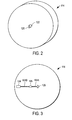
- analysis module 102 further includes a molded plug 114, a micro-channel disc 116 and a laminate layer 118 (depicted individually in FIGs. 2, 3 and 4, respectively).
- Analysis module 102 can be constructed by, for example, interfacing micro-channel disc 116 with laminate layer 118 and molded plug 114.
- Molded plug 114 includes an inlet channel 120 and a registration pole 122.
- Micro-channel disc 116 is configured to define (along with laminate layer 118) a liquid sample waste reservoir 124, as well as the aforementioned micro-channel 104 and sensor chamber 105.
- micro-channel disc 116 includes a registration hole 126 (see, for example, FIG. 3).
- Laminate layer 118 includes an access hole 128, a membrane valve 130, and in the embodiment of FIGs. 1-4, the aforementioned analyte sensor 106 and first and second position electrodes 108 and 110.
- Micro-channel 104 has cross-sectional dimensions perpendicular to a direction of fluid flow (i.e., height and width) in the range of about 10 micrometers to about 500 micrometers.
- Typical liquid sample volumes to be handled in a micro-channel(s) of embodiments of the present invention are on the order of about 10 nanoliters to about 10 microliters.
- the term "handled” is in reference to the transportation of various liquid sample volumes including, but not limited to, isolated liquid sample volumes extracted from a target site (e.g., isolated volumes in the range of 50 nl to 250 nl), the minimum liquid sample volume required by an analyte sensor (for example, 50 nl), and the total liquid sample volume that is conducted through a micro-channel throughout the useful lifetime of a microfluidic analytical system (for example, a total volume of approximately 10 micro-liters).
- isolated liquid sample volumes extracted from a target site e.g., isolated volumes in the range of 50 nl to 250 nl
- an analyte sensor for example, 50 nl
- the total liquid sample volume that is conducted through a micro-channel throughout the useful lifetime of a microfluidic analytical system for example, a total volume of approximately 10 micro-liters.
- Registration pole 122 of molded plug 114 is employed during manufacturing of microfluidic analytical system 100 to ensure adequate alignment (i.e., registration) of molded plug 114 and micro-channel disc 116. For example, such alignment must insure that analyte sensor 106 is operatively aligned with sensor chamber 105 and that first and second position electrodes 108 and 110 are aligned with post-sensor micro-channel channel 104b.
- laminate layer 118 can be aligned with micro-channel disc 116 using registration features included in laminate layer 118 and/or micro-channel disc 116 (not shown) or by optical verification.
- Registration hole 126 of micro-channel disc 116 is depicted as having a half circle shape and extending entirely through micro-channel disc 116.
- Registration pole 122 has a shape and size that are complementary to registration hole 126, thus providing for micro-channel disc 116 to securely interface with the molded plug 114, as depicted in FIG. 1.
- the use of half circle shapes for both registration hole 126 and registration pole 122 beneficially limits the rotational freedom of a combined molded plug 114 and micro-channel disc 116. It should be noted that alternative shapes other than a half circle can also be used.
- laminate layer 118 includes electrical connections to electrically connect analyte sensor 106 to external apparatus (such as a local controller module as described with respect to FIG. 5 below) and to connect first and second position electrodes 108 and 110 to meter 112.
- electrical connections can include, for example, conductive traces and electrical contact pads.
- a liquid sample (e.g., an ISF sample) will be transported to inlet channel 120 by suitable means, such as a sampling module as described below with respect to FIG. 5.
- Flow of liquid sample through inlet channel 120 is controlled by membrane valve 130.
- membrane valve 130 It should be noted that other types of valves, besides membrane valves, can be used and are well know to one skilled in the art.
- membrane valve 130 is deformable and made of an elastomeric material in a dome shape.
- a liquid sample may flow past membrane valve 130 and fill pre-sensor micro-channel portion 104a.
- membrane valve 130 is initially deformed (for example, by the application of pressure via access hole 128), it occludes inlet channel 120 and prevents liquid sample from flowing therethrough.
- further deformation of membrane valve 130 pushes liquid sample through pre-sensor micro-channel portion 104a and into sensor chamber 105.
- the movement of liquid sample past membrane valve 130 i.e., from inlet channel 120 to pre-sensor micro-channel portion 104a
- Typical liquid sample flow rates into micro-channel 104 are in the range of about 10 nanoliters per minute to about 1000 nanoliters per minute.
- First and second position electrodes 108 and 110 can be used to determine the liquid sample position within micro-channel 104, the flow rate of a liquid sample and/or the volume of an extracted liquid sample to help control the depression of membrane valve 130. It is beneficial to determine liquid sample position in order to ascertain when a minimum amount of liquid sample has been collected into analysis module 102 to initiate analyte determination.
- liquid sample flow rate and/or the total amount of liquid sample that has entered microfluidic analytical system 100 can also be beneficial to determine liquid sample flow rate and/or the total amount of liquid sample that has entered microfluidic analytical system 100 in order to control membrane valve 130 in a manner that facilitates semi-continuous stopped flow measurements (i.e., measurements taken with liquid sample flow momentarily halted and that result in a predetermined number of measurements per unit time [typically in the range of 4 to 10 measurements per hour] rather than a continuous measurement) over a predetermined time periods.
- determining liquid sample flow rate and the total amount of liquid sample enables sensor lag compensation.
- analyte sensor 106 may be sensitive to flow rate. Therefore, the use of first and second position electrodes and meter 112 allows system 100 to more accurately determine an analyte over an extended period of time such as, for example, about 8 hours.
- analyte sensor 106 is disposed within sensor chamber 105.
- Analyte sensor 106 can be any suitable sensor known to one skilled in the art.
- analyte sensor 106 can be an electrochemical glucose sensor that measures a current proportional to glucose concentration. More particularly, analyte sensor 106 can be, for example, an electrochemical glucose sensor that measures current under stopped flow conditions (i.e., flow rates at or near zero during measurement) and with glucose being consumed within sensor chamber 105.
- Examples of analyte sensors that may be used in embodiments of the present invention include, but not limited to, electrochemical-based and photometric-based analyte sensors.
- Electrochemical-based analyte sensors include, for example, amperometric, potentiometric and coulometric analyte sensors.
- Photometric-based analyte sensors include, for example, transmission, reflectance, colorimetric, fluorometric, scattering and absorbance analyte sensors.
- an analyte in a liquid sample After an analyte in a liquid sample has been determined by analyte sensor 106, the liquid sample is transported to post-sensor micro-channel portion 104b.
- analyte monitoring systems can be employed, for example, as a subsystem in a variety of devices.
- embodiments of the present invention can be employed as an analysis module of system 200 depicted in FIG. 5.
- System 200 is configured for extracting a bodily liquid sample (e.g., an ISF sample) and monitoring an analyte (e.g., glucose) therein.
- System 200 includes a disposable cartridge 212 (encompassed within the dashed box), a local controller module 214 and a remote controller module 216.
- disposable cartridge 212 includes a sampling module 218 for extracting the bodily liquid sample (namely, an ISF sample) from a body (B, for example, a user's skin layer) and an analysis module 200 for measuring an analyte (i.e., glucose) in the bodily fluid.
- Sampling module 218 can be any suitable sampling module known to those of skill in the art, while analysis module 220 can be a microfluidic analytical system according to embodiments of the present invention. Examples of suitable sampling modules are described in International Application PCT/GB01/05634 (published as WO 02/49507 A1 on June 27, 2002) and U.S. Patent Application No. 10/653,023, which is hereby fully incorporated herein by reference.
- sampling module 218 is configured to be disposable since it is a component of disposable cartridge 212.
- the sampling module 218 of system 200 is an ISF sampling module that includes a penetration member 222 for penetrating a target site (TS) of body B and extracting an ISF sample, a launching mechanism 224 and at least one pressure ring 228.
- Sampling module 218 is adapted to provide a continuous or semi-continuous flow of ISF to analysis module 220 for the monitoring (e.g., concentration measurement) of an analyte (such as glucose) in the ISF sample.
- an analyte such as glucose
- penetration member 222 is inserted into the target site (i.e., penetrates the target site) by operation of launching mechanism 224.
- penetration member 222 can be inserted to a maximum insertion depth in the range of, for example, 1.5 mm to 3 mm.
- penetration member 222 can be configured to optimize extraction of an ISF sample in a continuous or semi-continuous manner.
- penetration member 222 can include, for example, a 25 gauge, thin-wall stainless steel needle (not shown in FIGs. 5 or 6) with a bent tip, wherein a fulcrum for the tip bend is disposed between the needle's tip and the needle's heel.
- Suitable needles for use in penetration members are described in U.S. Patent Application No. 10/185,605 (published as US 2003/0060784 A1 on March 27, 2003). Furthermore, further details regarding system 200 are in U.S. Patent Application No. 10/718,818.
- FIG. 7 is a simplified schematic diagram of a position electrode, micro-channel, analyte sensor and meter configuration 300 for use in embodiments of microfluidic analytical systems according to the present invention.
- Configuration 300 includes first position electrode 302, second position electrode 304, electrical impedance meter 306, timer 308, micro-channel 310 and analyte sensor 312.
- wavy lines depict a liquid sample (e.g., an ISF, blood, urine, plasma, serum, buffer or reagent liquid sample) within micro-channel 310.
- Configuration 300 can be used to determine the position or flow rate of a liquid sample in micro-channel 310.
- analyte sensor 312 is located in-between first position electrode 302 and second position electrode 304.
- Electrical impedance meter 306 is adapted for measuring an electrical impedance between first position electrode 302 and second electrode 304. Such a measurement can be accomplished by, for example, employing a voltage source to impose either a continuous or alternating voltage between first position electrode 302 and second position electrode 304 such that an impedance resulting from a conducting path formed by a liquid sample within micro-channel 310 and between first position electrode 302 and second position electrode 304 can be measured, yielding a signal indicative of the presence of the liquid sample.
- a signal can be sent to timer 308 to mark the time at which liquid is first present between the first and second position electrodes.
- another signal can be sent to timer 308.
- the difference in time between when a liquid sample is first present between the first and second position electrodes and when the liquid sample reaches the second position electrode can be used to determine liquid sample flow rate (given knowledge of the volume of micro-channel 310 between the first and second position electrodes). Furthermore, knowledge of liquid sample flow rate and/or liquid sample position can be used to determine total liquid sample volume.
- a signal denoting the point in time at which a liquid sample arrives at second position electrode 304 can also be sent to a local controller module (e.g., local controller module 214 of FIG. 5) for use in determining the proper deformed state for membrane valve 130.
- a local controller module e.g., local controller module 214 of FIG. 5
- FIG. 8A is a simplified cross-sectional and schematic diagram illustrating a manner in which a position electrode can be in operative communication with a micro-channel in embodiments of microfluidic analytical systems according to the present invention.
- FIG. 8A depicts a micro-channel 350 (in cross-section), a micro-channel disc 352, a position electrode 354, a laminate layer 356 and a meter 358.
- position electrode 354 is in operative communication with the micro-channel 350 such that a surface 360 of position electrode 354 is exposed to liquid sample (depicted by the wavy lines in FIG. 8A) in micro-channel 350.
- micro-channel disc 352 and laminate layer 356 are made of electrically insulating material such as, for example, polymeric insulating materials (e.g., polystyrene, silicone rubber, PMMA, polycarbonate or PEEK) and non-polymeric insulating materials such as, for, example, glass.
- electrically insulating material such as, for example, polymeric insulating materials (e.g., polystyrene, silicone rubber, PMMA, polycarbonate or PEEK) and non-polymeric insulating materials such as, for, example, glass.
- FIG. 8B is a simplified cross-sectional and schematic diagram (employing the same labeling numerals as FIG. 8A) illustrating another manner by which a position electrode can be in operative communication with a micro-channel in embodiments of microfluidic analytical systems according to the present invention.
- FIG. 8B depicts a micro-channel 350 (in cross-section), a micro-channel disc 352, a position electrode 354, a laminate layer 356 and a meter 358.
- position electrode 354 is in operative communication with the micro-channel 350 but separated from micro-channel 350 by an insulating layer, namely a portion of laminate layer 356.
- a benefit of the manner depicted in FIG. 8B is that there is no direct contact between liquid sample in micro-channel 350 and position electrode 354 and, consequently, no electrolysis or electrochemical decomposition of the liquid sample due to position electrode 354 can occur.
- FIG. 9 is simplified schematic diagram of another micro-channel, analyte sensor and position electrode configuration 400 for use in embodiments of microfluidic analytical systems according to the present invention.
- Configuration 400 includes first position electrode 402, second position electrode 404, electrical impedance meter 406, timer 408, micro-channel 410 and analyte sensor 412.
- wavy lines depict a liquid sample (e.g., an ISF, blood, urine, plasma, serum, buffer or reagent liquid sample) within micro-channel 410.
- both first position electrode 402 and analyte sensor 412 are in operative communication with local controller module 214.
- first position electrode can serve both as a position electrode and as a reference electrode for analyte sensor 412 (assuming that analyte sensor 412 is an electrochemical-based analyte sensor).
- electrical impedance meter 406 and timer 408 may be incorporated into local controller module 214.
- first position electrode 402 can, for example, be manufactured of a material that results in a stable electrical potential between the first position electrode and the liquid sample.
- the first position electrode can be formed of chlorinated silver (Ag/AgCl).
- FIG. 10 is a simplified schematic diagram of yet another position electrode, micro-channel, analyte sensor and meter configuration 450 for use in embodiments of microfluidic analytical systems according to the present invention.
- Configuration 450 includes first, second and third position electrodes 452, 454 and 456, respectively, an analyte sensor 458, an electrical impedance meter 460, timer 462, and micro-channel 464.
- Electrical impedance meter 460 is configured to measure the electrical impedance between any two of the first, second and third position electrodes.
- Configuration 450 differs from configurations 300 and 400 in that configuration 450 includes three position electrodes.
- the inclusion of three position electrodes provides for an improved ability to accurately detect the position and flow rate of a liquid sample within micro-channel 464.
- the use of two position electrodes enables the detection of a single bolus (i.e., the volume contained in a micro-channel between the two position electrodes).
- the use of three (or more) position electrodes enables the detection of multiple boluses as the liquid sample sequentially passes the three (or more) position electrodes.
- FIG. 11 is simplified schematic diagram of a position electrode, micro-channel (comprised of a main micro-channel and two branch micro-channels), analyte sensor and meter configuration 500 for use in embodiments of microfluidic analytical systems according to the present invention.
- Configuration 500 includes a micro-channel comprised of main micro-channel 502, first branch micro-channel 504 and second branch micro-channel 506.
- Configuration 500 also includes first position electrode 508 (in operative communication with main micro-channel 502), second position electrode 510 (in operative communication with first branch micro-channel 504) and third position electrode 512 (in operative communication with second branch micro-channel 506).
- configuration 500 includes a first analyte sensor 514 (in operative communication with first branch micro-channel 504) and a second analyte sensor 516 (in operative communication with second branch micro-channel 506), a meter 518 and timer 520.
- Meter 518 is configured to measure an electrical characteristic (e.g., impedance) between the first position electrode and either of the second and third position electrodes.
- configuration 500 will be employed in a device that includes liquid handling means for selectively directing a liquid sample from main micro-channel 502 to either of first and second branch micro-channels 504 and 506.
- liquid handling means include, but are not limited to, active valves, passive valves, capillary breaks, air pressure barriers and hydrophobic patches.
- Configuration 500 can be employed to detect the position of a liquid sample in either first branch micro-channel 504 (by employing meter 518 to measure an electrical characteristic between first position electrode 508 and second position electrode 510) or second branch micro-channel 506 (by employing meter 518 to measure an electrical characteristic between first position electrode 508 and third position electrode 512). Such detection(s) can be employed to control liquid sample flow and the determination of an analyte in the liquid sample by either first analyte sensor 514 or second analyte sensor 516.
- FIG. 11 is simplified schematic diagram of another position electrode, micro-channel (comprised of a main micro-channel and two branch micro-channels), analyte sensor and meter configuration 550 for use in embodiments of microfluidic analytical systems according to the present invention.
- Configuration 550 includes a micro-channel comprised of main micro-channel 552, first branch micro-channel 554 and second branch micro-channel 556.
- Configuration 550 also includes first and second position electrodes 558 and 560 (in operative communication with first branch micro-channel 554), and third and fourth position electrodes 562 and 564 (in operative communication with second branch micro-channel 556).
- configuration 550 includes a first analyte sensor 566 (in operative communication with first branch micro-channel 554) and a second analyte sensor 568 (in operative communication with second branch micro-channel 556), a meter 570 and timer 572.
- Meter 570 is configured to measure an electrical characteristic (e.g., impedance) between either of the first and second position electrodes and the third and fourth position electrodes.
- configuration 550 will be employed in a device that includes liquid handling means for selectively directing a liquid sample from main micro-channel 552 to either of first and second branch micro-channels 554 and 556.
- liquid handling means include, but are not limited to, active valves, passive valves, capillary breaks, air pressure barriers and hydrophobic patches.
- Configuration 550 can be employed to detect the position of a liquid sample in either first branch micro-channel 554 (by employing meter 570 to measure an electrical characteristic between first position electrode 558 and second position electrode 560) or second branch micro-channel 556 (by employing meter 570 to measure an electrical characteristic between third position electrode 562 and fourth position electrode 564). Such detection(s) can be employed to control liquid sample flow and the determination of an analyte in the liquid sample by either first analyte sensor 566 or second analyte sensor 568.
- a benefit of configuration 550 is that the first and second position electrodes (as well as the third and fourth position electrodes) can be positioned relatively close together to enable accurate measurements of relatively high electrical characteristics (e.g., relatively high impedances) therebetween.
- FIG. 13 is a simplified schematic diagram of a position electrode, micro-channel and meter configuration 600 for use in embodiments of microfluidic analytical systems according to the present invention.
- FIG. 14 is a simplified schematic diagram of an equivalent electrical circuit for a portion of configuration 600 of FIG. 13.
- Configuration 600 includes a first position electrode 602 and a second position electrode 604 in an interdigitated configuration.
- Configuration 600 also includes a micro-channel 606 and a meter 608.
- First and second position electrodes 602 and 604 each having a plurality of electrode portions that are placed substantially parallel to, and in alternating succession with, each other (e.g., in an alternating, "finger-like" pattern as depicted in FIG. 13).
- four electrode portions for first and second position electrodes 602 and 604 (602a and 604a, respectively) are illustrated in FIG. 13.
- the interdigitated electrode portions are also referred to as "fingers.”
- the position electrodes of embodiments of the present invention and the spacing therebetween can be of any suitable dimension.
- an interdigitated configuration can be employed with dimensions (e.g., dimensions Wg and W e of FIG. 13) that allow for the measurement of electrical properties of a relatively small liquid sample.
- each "finger” can independently have a width W e in the range of, for example, from about 1 micrometers to about 1500 micrometers.
- the separation between electrode “fingers” (W g ) can be, for example, in the range between about 0.1 millimeters and about 15 millimeters.
- the thickness of the position electrodes is sufficient to support a desired electric current. Exemplary thicknesses are, for example, in the range from about 1 micrometers to about 100 micrometers.
- Interdigitated configurations such as configuration 600 can have any number of "fingers” that are sufficient to provide utility, e.g., providing contact with a liquid sample and to measure an electrical characteristic.
- An interdigitated configuration can have, for example, from 2 to about 100 "fingers.”
- Configuration 600 can be employed to detect a liquid sample bolus(es) flowing through micro-channel 606. With such boluses having a pre-determined volume (such as for example 250 nanoliters) defined by the height and width of micro-channel 606 and the distance W g . For example, if micro-channel 606 has a height and width that are both about 250 microns, W e is about 0.5 millimeters and W g is about 4 millimeters, then when there is no liquid sample bridging between any finger of position electrode 602 and position electrode 604, the resistance between first electrode 602 and second electrode 604 is essentially infinity.
- a pre-determined volume such as for example 250 nanoliters
- each finger R e is much less than R I by at least about a factor of ten.
- the measured total resistance R T between first position electrode 602 and second position electrode 604 further decreases.
- Configuration 600 is particularly useful when R e is much less than R I .
- micro-channel 606 is depicted as passing (i.e., coming into operative communication with) each electrode finger 602a one time.
- micro-channel 606 could alternatively have a serpentine configuration such that micro-channel 606 passes each electrode finger 602a a plurality of times.
- Such a configuration can enhance the ability to easily resolve relatively small liquid sample volumes (e.g., liquid sample volumes of less than 5 nl).
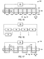
- FIG. 15 is a simplified schematic diagram of a position electrode, micro-channel and meter configuration 650 for use in embodiments of microfluidic analytical systems according to the present invention.
- FIG. 16 is a simplified schematic diagram of an equivalent electrical circuit for a portion of configuration 600 of FIG. 15.
- Configuration 650 includes a single comb-shaped position electrode 652 with eight "fingers" 652a, a micro-channel 654 and a meter 656. Electrode fingers 652a serve to define electrode segments therebetween with each segment having a resistance R e (as depicted in FIG. 16). It should be noted that the dimensions Wg and W e of FIG. 16 can be the same as described previously with respect to configuration 600.
- a measured total resistance of position electrode 652 is the summation of the resistance for each electrode segment R e (i.e., the resistance of all electrode elements together).
- the measured total resistance R T decreases since resistance R I is created in parallel to R e (see FIG. 16). It should be noted that with respect to configuration 650, the resistance of each electrode segment R e is significantly greater than R I , preferably by about a factor of ten or greater.
- FIG. 17 is a simplified schematic diagram of a position electrode, micro-channel and meter configuration 700 for use in embodiments of microfluidic analytical systems according to the present invention.
- Configuration 700 includes a single serpentine-shaped position electrode 702, a micro-channel 704 and a meter 706.
- FIG. 18 is a simplified schematic diagram of a position electrode, micro-channel and meter configuration 750 for use in embodiments of microfluidic analytical systems according to the present invention.
- FIG. 19 is a simplified schematic diagram of an equivalent electrical circuit for a portion of configuration 750 of FIG. 18.
- Configuration 750 includes a position electrode 752, micro-channel 754, bypass electrode 756, and meter 758.
- Position electrode 752 is a single comb-shaped position electrode with eight electrode “fingers" 752a. Electrode fingers 752a serve to define electrode segments therebetween with each segment having a resistance R e (as depicted in FIG. 18). It should be noted that the dimensions W g and W e of FIG. 18 can be the same as described previously with respect to configuration 600.
- bypass electrode 756 In the absence of any liquid sample, bypass electrode 756 is electrically floating. However, when a liquid sample is present between two consecutive electrode fingers 752a, bypass electrode 756 becomes a part of the circuit depicted in FIG. 19 and is characterized by resistance R b .
- bypass electrode 756 effectively reduces the R T , as shown schematically in FIG. 19.
- a bypass electrode(s) can be similarly disposed between position electrodes or between electrode fingers in a variety of electrode configurations (for example, the configurations of FIGs. 7, 9-13 and 17) to reduce total measured resistance in the presence of a relatively high-resistive liquid sample.
- FIG. 20 is a simplified schematic diagram of a position electrode, micro-channel and meter configuration 800 for use in embodiments of microfluidic analytical systems according to the present invention.
- Configuration 800 includes a position electrode 802, micro-channel 804 and meter 806.
- Meter 806 is configured to measure a continually changing electrical characteristic of position electrode 802 as a liquid sample (depicted by the wavy lines in FIG. 20) passes through micro-channel 804.
- the first and second position electrodes of the configuration were formed from Ag/AgCl using a screen printing technique.
- the first position electrode and second position electrode were separated by a distance W g of 4 millimeters.
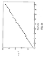
- FIG. 21 shows that the measured total admittance AT increases linearly as successive liquid sample boluses pass each of the electrode fingers of the configuration.
- FIG. 21 illustrates that each successive bolus was detected as a change in admittance. Therefore, boluses can be counted by, for example, monitoring for spikes in the derivative of a measured impedance signal versus time.
Landscapes
- Health & Medical Sciences (AREA)
- Chemical & Material Sciences (AREA)
- Life Sciences & Earth Sciences (AREA)
- Physics & Mathematics (AREA)
- Engineering & Computer Science (AREA)
- General Physics & Mathematics (AREA)
- General Health & Medical Sciences (AREA)
- Hematology (AREA)
- Molecular Biology (AREA)
- Chemical Kinetics & Catalysis (AREA)
- Pathology (AREA)
- Analytical Chemistry (AREA)
- Fluid Mechanics (AREA)
- Optics & Photonics (AREA)
- Surgery (AREA)
- Emergency Medicine (AREA)
- Biochemistry (AREA)
- Biophysics (AREA)
- Electrochemistry (AREA)
- Biomedical Technology (AREA)
- Heart & Thoracic Surgery (AREA)
- Medical Informatics (AREA)
- Immunology (AREA)
- Animal Behavior & Ethology (AREA)
- Public Health (AREA)
- Veterinary Medicine (AREA)
- Clinical Laboratory Science (AREA)
- Combustion & Propulsion (AREA)
- Mechanical Engineering (AREA)
- General Engineering & Computer Science (AREA)
- Dispersion Chemistry (AREA)
- Power Engineering (AREA)
- Investigating Or Analyzing Materials By The Use Of Electric Means (AREA)
Applications Claiming Priority (2)
| Application Number | Priority Date | Filing Date | Title |
|---|---|---|---|
| US811446 | 1985-12-20 | ||
| US10/811,446 US6990849B2 (en) | 2004-03-26 | 2004-03-26 | Microfluidic analytical system with position electrodes |
Publications (1)
| Publication Number | Publication Date |
|---|---|
| EP1580552A1 true EP1580552A1 (de) | 2005-09-28 |
Family
ID=34862131
Family Applications (1)
| Application Number | Title | Priority Date | Filing Date |
|---|---|---|---|
| EP05251850A Withdrawn EP1580552A1 (de) | 2004-03-26 | 2005-03-24 | Mikrofluidisches Analysesystem mit Positionselektroden |
Country Status (9)
| Country | Link |
|---|---|
| US (1) | US6990849B2 (de) |
| EP (1) | EP1580552A1 (de) |
| JP (1) | JP2005283581A (de) |
| KR (1) | KR20060044681A (de) |
| CN (1) | CN1673750A (de) |
| AU (1) | AU2005200903A1 (de) |
| CA (1) | CA2502060A1 (de) |
| SG (1) | SG115779A1 (de) |
| TW (1) | TW200602634A (de) |
Cited By (4)
| Publication number | Priority date | Publication date | Assignee | Title |
|---|---|---|---|---|
| CN103293198A (zh) * | 2008-07-02 | 2013-09-11 | 孙一慧 | 用于检测在流体中的分析物的传感器仪器系统及方法 |
| WO2015044406A1 (en) * | 2013-09-30 | 2015-04-02 | Cilag Gmbh International | Test strip resistance check |
| US10926255B2 (en) | 2015-05-21 | 2021-02-23 | Nokia Technologies Oy | Apparatus and method for providing a time varying voltage |
| US20220008919A1 (en) * | 2020-07-07 | 2022-01-13 | International Business Machines Corporation | Electrical tracking of a multiphase microfluidic flow |
Families Citing this family (91)
| Publication number | Priority date | Publication date | Assignee | Title |
|---|---|---|---|---|
| US6036924A (en) * | 1997-12-04 | 2000-03-14 | Hewlett-Packard Company | Cassette of lancet cartridges for sampling blood |
| US6391005B1 (en) | 1998-03-30 | 2002-05-21 | Agilent Technologies, Inc. | Apparatus and method for penetration with shaft having a sensor for sensing penetration depth |
| DE10057832C1 (de) | 2000-11-21 | 2002-02-21 | Hartmann Paul Ag | Blutanalysegerät |
| US8641644B2 (en) | 2000-11-21 | 2014-02-04 | Sanofi-Aventis Deutschland Gmbh | Blood testing apparatus having a rotatable cartridge with multiple lancing elements and testing means |
| US7981056B2 (en) | 2002-04-19 | 2011-07-19 | Pelikan Technologies, Inc. | Methods and apparatus for lancet actuation |
| CA2448681C (en) | 2001-06-12 | 2014-09-09 | Pelikan Technologies, Inc. | Integrated blood sampling analysis system with multi-use sampling module |
| ATE497731T1 (de) * | 2001-06-12 | 2011-02-15 | Pelikan Technologies Inc | Gerät zur erhöhung der erfolgsrate im hinblick auf die durch einen fingerstich erhaltene blutausbeute |
| US7041068B2 (en) | 2001-06-12 | 2006-05-09 | Pelikan Technologies, Inc. | Sampling module device and method |
| US9427532B2 (en) | 2001-06-12 | 2016-08-30 | Sanofi-Aventis Deutschland Gmbh | Tissue penetration device |
| ES2336081T3 (es) | 2001-06-12 | 2010-04-08 | Pelikan Technologies Inc. | Dispositivo de puncion de auto-optimizacion con medios de adaptacion a variaciones temporales en las propiedades cutaneas. |
| US8337419B2 (en) | 2002-04-19 | 2012-12-25 | Sanofi-Aventis Deutschland Gmbh | Tissue penetration device |
| US9795747B2 (en) | 2010-06-02 | 2017-10-24 | Sanofi-Aventis Deutschland Gmbh | Methods and apparatus for lancet actuation |
| ATE485766T1 (de) | 2001-06-12 | 2010-11-15 | Pelikan Technologies Inc | Elektrisches betätigungselement für eine lanzette |
| AU2002312521A1 (en) * | 2001-06-12 | 2002-12-23 | Pelikan Technologies, Inc. | Blood sampling apparatus and method |
| AU2002348683A1 (en) | 2001-06-12 | 2002-12-23 | Pelikan Technologies, Inc. | Method and apparatus for lancet launching device integrated onto a blood-sampling cartridge |
| US9226699B2 (en) | 2002-04-19 | 2016-01-05 | Sanofi-Aventis Deutschland Gmbh | Body fluid sampling module with a continuous compression tissue interface surface |
| US7344894B2 (en) | 2001-10-16 | 2008-03-18 | Agilent Technologies, Inc. | Thermal regulation of fluidic samples within a diagnostic cartridge |
| US8579831B2 (en) | 2002-04-19 | 2013-11-12 | Sanofi-Aventis Deutschland Gmbh | Method and apparatus for penetrating tissue |
| US7175642B2 (en) | 2002-04-19 | 2007-02-13 | Pelikan Technologies, Inc. | Methods and apparatus for lancet actuation |
| US8267870B2 (en) | 2002-04-19 | 2012-09-18 | Sanofi-Aventis Deutschland Gmbh | Method and apparatus for body fluid sampling with hybrid actuation |
| US7481776B2 (en) * | 2002-04-19 | 2009-01-27 | Pelikan Technologies, Inc. | Method and apparatus for penetrating tissue |
| US7331931B2 (en) * | 2002-04-19 | 2008-02-19 | Pelikan Technologies, Inc. | Method and apparatus for penetrating tissue |
| US7524293B2 (en) | 2002-04-19 | 2009-04-28 | Pelikan Technologies, Inc. | Method and apparatus for penetrating tissue |
| US7547287B2 (en) * | 2002-04-19 | 2009-06-16 | Pelikan Technologies, Inc. | Method and apparatus for penetrating tissue |
| US9248267B2 (en) | 2002-04-19 | 2016-02-02 | Sanofi-Aventis Deustchland Gmbh | Tissue penetration device |
| US7232451B2 (en) * | 2002-04-19 | 2007-06-19 | Pelikan Technologies, Inc. | Method and apparatus for penetrating tissue |
| US7229458B2 (en) | 2002-04-19 | 2007-06-12 | Pelikan Technologies, Inc. | Method and apparatus for penetrating tissue |
| US8221334B2 (en) | 2002-04-19 | 2012-07-17 | Sanofi-Aventis Deutschland Gmbh | Method and apparatus for penetrating tissue |
| US7485128B2 (en) * | 2002-04-19 | 2009-02-03 | Pelikan Technologies, Inc. | Method and apparatus for penetrating tissue |
| US8702624B2 (en) | 2006-09-29 | 2014-04-22 | Sanofi-Aventis Deutschland Gmbh | Analyte measurement device with a single shot actuator |
| US7909778B2 (en) * | 2002-04-19 | 2011-03-22 | Pelikan Technologies, Inc. | Method and apparatus for penetrating tissue |
| US7141058B2 (en) * | 2002-04-19 | 2006-11-28 | Pelikan Technologies, Inc. | Method and apparatus for a body fluid sampling device using illumination |
| US7291117B2 (en) | 2002-04-19 | 2007-11-06 | Pelikan Technologies, Inc. | Method and apparatus for penetrating tissue |
| US7410468B2 (en) * | 2002-04-19 | 2008-08-12 | Pelikan Technologies, Inc. | Method and apparatus for penetrating tissue |
| US7648468B2 (en) | 2002-04-19 | 2010-01-19 | Pelikon Technologies, Inc. | Method and apparatus for penetrating tissue |
| US7226461B2 (en) | 2002-04-19 | 2007-06-05 | Pelikan Technologies, Inc. | Method and apparatus for a multi-use body fluid sampling device with sterility barrier release |
| US7374544B2 (en) | 2002-04-19 | 2008-05-20 | Pelikan Technologies, Inc. | Method and apparatus for penetrating tissue |
| US7491178B2 (en) | 2002-04-19 | 2009-02-17 | Pelikan Technologies, Inc. | Method and apparatus for penetrating tissue |
| US9314194B2 (en) | 2002-04-19 | 2016-04-19 | Sanofi-Aventis Deutschland Gmbh | Tissue penetration device |
| US7892183B2 (en) | 2002-04-19 | 2011-02-22 | Pelikan Technologies, Inc. | Method and apparatus for body fluid sampling and analyte sensing |
| US8784335B2 (en) | 2002-04-19 | 2014-07-22 | Sanofi-Aventis Deutschland Gmbh | Body fluid sampling device with a capacitive sensor |
| US7976476B2 (en) * | 2002-04-19 | 2011-07-12 | Pelikan Technologies, Inc. | Device and method for variable speed lancet |
| US7901362B2 (en) * | 2002-04-19 | 2011-03-08 | Pelikan Technologies, Inc. | Method and apparatus for penetrating tissue |
| US7674232B2 (en) | 2002-04-19 | 2010-03-09 | Pelikan Technologies, Inc. | Method and apparatus for penetrating tissue |
| US7717863B2 (en) | 2002-04-19 | 2010-05-18 | Pelikan Technologies, Inc. | Method and apparatus for penetrating tissue |
| US7297122B2 (en) * | 2002-04-19 | 2007-11-20 | Pelikan Technologies, Inc. | Method and apparatus for penetrating tissue |
| US9795334B2 (en) | 2002-04-19 | 2017-10-24 | Sanofi-Aventis Deutschland Gmbh | Method and apparatus for penetrating tissue |
| US7563232B2 (en) * | 2002-04-19 | 2009-07-21 | Pelikan Technologies, Inc. | Method and apparatus for penetrating tissue |
| US7582099B2 (en) | 2002-04-19 | 2009-09-01 | Pelikan Technologies, Inc | Method and apparatus for penetrating tissue |
| US7371247B2 (en) * | 2002-04-19 | 2008-05-13 | Pelikan Technologies, Inc | Method and apparatus for penetrating tissue |
| US8574895B2 (en) | 2002-12-30 | 2013-11-05 | Sanofi-Aventis Deutschland Gmbh | Method and apparatus using optical techniques to measure analyte levels |
| WO2004060174A2 (en) * | 2002-12-31 | 2004-07-22 | Pelikan Technologies Inc. | Method and apparatus for loading penetrating members |
| EP1633235B1 (de) | 2003-06-06 | 2014-05-21 | Sanofi-Aventis Deutschland GmbH | Gerät für die entnahme von körperflüssigkeiten und analyten-nachweis |
| WO2005006939A2 (en) * | 2003-06-11 | 2005-01-27 | Pelikan Technologies, Inc. | Method and apparatus for body fluid sampling and analyte sensing |
| WO2006001797A1 (en) | 2004-06-14 | 2006-01-05 | Pelikan Technologies, Inc. | Low pain penetrating |
| US7604592B2 (en) | 2003-06-13 | 2009-10-20 | Pelikan Technologies, Inc. | Method and apparatus for a point of care device |
| EP1671096A4 (de) | 2003-09-29 | 2009-09-16 | Pelikan Technologies Inc | Verfahren und apparatur für eine verbesserte probeneinfangvorrichtung |
| US9351680B2 (en) * | 2003-10-14 | 2016-05-31 | Sanofi-Aventis Deutschland Gmbh | Method and apparatus for a variable user interface |
| US7822454B1 (en) | 2005-01-03 | 2010-10-26 | Pelikan Technologies, Inc. | Fluid sampling device with improved analyte detecting member configuration |
| EP1706026B1 (de) | 2003-12-31 | 2017-03-01 | Sanofi-Aventis Deutschland GmbH | Verfahren und vorrichtung zur verbesserung der fluidströmung und der probennahme |
| US20050220644A1 (en) * | 2004-03-31 | 2005-10-06 | Sebastian Bohm | Pneumatic actuator for bolus generation in a fluid handling circuit |
| US7665303B2 (en) * | 2004-03-31 | 2010-02-23 | Lifescan Scotland, Ltd. | Method of segregating a bolus of fluid using a pneumatic actuator in a fluid handling circuit |
| US20050217742A1 (en) * | 2004-03-31 | 2005-10-06 | Sebastian Bohm | Microfluidic circuit including an array of triggerable passive valves |
| WO2006011062A2 (en) | 2004-05-20 | 2006-02-02 | Albatros Technologies Gmbh & Co. Kg | Printable hydrogel for biosensors |
| WO2005120365A1 (en) | 2004-06-03 | 2005-12-22 | Pelikan Technologies, Inc. | Method and apparatus for a fluid sampling device |
| US7722809B2 (en) * | 2004-06-04 | 2010-05-25 | Wisconsin Alumni Research Foundation | Bioagent detection device |
| US7402616B2 (en) | 2004-09-30 | 2008-07-22 | Lifescan, Inc. | Fusible conductive ink for use in manufacturing microfluidic analytical systems |
| US20060065532A1 (en) * | 2004-09-30 | 2006-03-30 | Matthias Stiene | Microfluidic analytical system with accessible electrically conductive contact pads |
| US8652831B2 (en) | 2004-12-30 | 2014-02-18 | Sanofi-Aventis Deutschland Gmbh | Method and apparatus for analyte measurement test time |
| US20100145158A1 (en) * | 2005-10-06 | 2010-06-10 | Hamilton Scott E | Pod Connected Data Monitoring System |
| JP4686723B2 (ja) * | 2006-08-24 | 2011-05-25 | 独立行政法人国立高等専門学校機構 | 光学的分析装置 |
| US20080076969A1 (en) * | 2006-08-29 | 2008-03-27 | Ulrich Kraft | Methods for modifying control software of electronic medical devices |
| CN101657150B (zh) * | 2007-01-26 | 2013-04-03 | 弗洛西恩公司 | 用于分析系统的传感器 |
| KR100969667B1 (ko) * | 2008-03-24 | 2010-07-14 | 디지탈 지노믹스(주) | 생리활성물질을 전기적으로 검출하는 방법 및 이를 위한바이오칩 |
| WO2009126900A1 (en) | 2008-04-11 | 2009-10-15 | Pelikan Technologies, Inc. | Method and apparatus for analyte detecting device |
| WO2009132473A1 (zh) * | 2008-04-28 | 2009-11-05 | 西门子公司 | 集成化的原位生物传感器 |
| US9375169B2 (en) | 2009-01-30 | 2016-06-28 | Sanofi-Aventis Deutschland Gmbh | Cam drive for managing disposable penetrating member actions with a single motor and motor and control system |
| KR20110080067A (ko) * | 2010-01-04 | 2011-07-12 | 엘지전자 주식회사 | 샘플분석 카트리지 및 샘플분석 카트리지 리더 |
| US8965476B2 (en) | 2010-04-16 | 2015-02-24 | Sanofi-Aventis Deutschland Gmbh | Tissue penetration device |
| WO2013137499A1 (ko) * | 2012-03-14 | 2013-09-19 | 엘지전자 주식회사 | 바이오센서 |
| US9714853B2 (en) | 2013-03-14 | 2017-07-25 | Alfred E. Mann Foundation For Scientific Research | Microfluidic flow rate sensor |
| US10213140B2 (en) | 2013-05-17 | 2019-02-26 | Johnson & Johnson Vision Care, Inc. | Ophthalmic lens with a microfluidic system |
| US10196678B2 (en) * | 2014-10-06 | 2019-02-05 | ALVEO Technologies Inc. | System and method for detection of nucleic acids |
| WO2016210128A1 (en) | 2015-06-25 | 2016-12-29 | Cytonome/St, Llc | Microfluidic device and system using acoustic manipulation |
| WO2017070602A1 (en) * | 2015-10-22 | 2017-04-27 | Georgia Tech Research Corporation | Electronic sensors for multiplexed detection of particles on microfluidic chips and uses thereof |
| US10502756B2 (en) * | 2016-08-26 | 2019-12-10 | Robert Bosch Gmbh | Flexible microfluidic motion sensors |
| US11346805B2 (en) * | 2017-02-07 | 2022-05-31 | Colorado State University Research Foundation | Handheld electrochemical sensing platform |
| TWI653968B (zh) * | 2017-11-20 | 2019-03-21 | 研能科技股份有限公司 | 血糖偵測裝置 |
| US12582984B1 (en) | 2020-07-02 | 2026-03-24 | Argonaut Manufacturing Services, Inc. | Method for lyophilization and device thereof |
| EP4301238A1 (de) | 2021-03-03 | 2024-01-10 | Withings | Volumen- und durchflusssensor und zugehöriges injektionsgerät |
| US12270777B2 (en) * | 2023-06-28 | 2025-04-08 | International Business Machines Corporation | 2D microfluidic structure |
Citations (5)
| Publication number | Priority date | Publication date | Assignee | Title |
|---|---|---|---|---|
| EP0537761A2 (de) * | 1991-10-18 | 1993-04-21 | Matsushita Electric Industrial Co., Ltd. | Biosensor und Verfahren zur Messung einer Konzentration eines Substrats in eine Probe |
| WO2000047322A2 (en) * | 1999-02-12 | 2000-08-17 | Board Of Regents, The University Of Texas System | Method and apparatus for programmable fluidic processing |
| WO2002050534A1 (en) * | 2000-12-19 | 2002-06-27 | Inverness Medical Limited | Device for measuring blood coagulation and method thereof |
| WO2002101343A2 (en) * | 2001-06-12 | 2002-12-19 | Pelikan Technologies, Inc. | Thermal sensor for fluid detection |
| WO2003091717A1 (en) * | 2002-04-25 | 2003-11-06 | Home Diagnostics, Inc. | Systems and methods for blood glucose sensing |
Family Cites Families (12)
| Publication number | Priority date | Publication date | Assignee | Title |
|---|---|---|---|---|
| US60784A (en) * | 1867-01-01 | Edward powell | ||
| US155237A (en) * | 1874-09-22 | Improvement in magneto-electric machines | ||
| US4169377A (en) * | 1978-04-17 | 1979-10-02 | Nalco Chemical Company | Quantity sensing system for a container |
| JPH0324425A (ja) * | 1989-06-20 | 1991-02-01 | Murata Mfg Co Ltd | 変位量計測装置 |
| US5226313A (en) * | 1989-12-15 | 1993-07-13 | Murata Mfg. Co., Ltd. | Body fluid excretion measurement apparatus for medical application |
| JPH0752113B2 (ja) * | 1990-05-08 | 1995-06-05 | 株式会社村田製作所 | 液面センサ |
| US5719556A (en) * | 1995-05-22 | 1998-02-17 | Albin; Robert | Liquid level sensor utilizing AC and resistance |
| US5932799A (en) * | 1997-07-21 | 1999-08-03 | Ysi Incorporated | Microfluidic analyzer module |
| ATE290821T1 (de) | 1999-02-04 | 2005-04-15 | Integ Inc | Nadel für körperflüssigkeitstestsatz |
| US7122152B2 (en) * | 1999-05-10 | 2006-10-17 | University Of Florida | Spatiotemporal and geometric optimization of sensor arrays for detecting analytes fluids |
| DE19944331B4 (de) | 1999-09-15 | 2006-03-30 | Fraunhofer-Gesellschaft zur Förderung der angewandten Forschung e.V. | Mikrosensoranordnung zur Positionsmessung von Flüssigkeiten in Kapillaren |
| US7276146B2 (en) | 2001-11-16 | 2007-10-02 | Roche Diagnostics Operations, Inc. | Electrodes, methods, apparatuses comprising micro-electrode arrays |
-
2004
- 2004-03-26 US US10/811,446 patent/US6990849B2/en not_active Expired - Lifetime
-
2005
- 2005-02-28 AU AU2005200903A patent/AU2005200903A1/en not_active Abandoned
- 2005-03-18 SG SG200501707A patent/SG115779A1/en unknown
- 2005-03-22 CA CA002502060A patent/CA2502060A1/en not_active Abandoned
- 2005-03-24 KR KR1020050024484A patent/KR20060044681A/ko not_active Withdrawn
- 2005-03-24 CN CNA2005100637398A patent/CN1673750A/zh active Pending
- 2005-03-24 EP EP05251850A patent/EP1580552A1/de not_active Withdrawn
- 2005-03-25 JP JP2005089364A patent/JP2005283581A/ja active Pending
- 2005-03-25 TW TW094109212A patent/TW200602634A/zh unknown
Patent Citations (6)
| Publication number | Priority date | Publication date | Assignee | Title |
|---|---|---|---|---|
| EP0537761A2 (de) * | 1991-10-18 | 1993-04-21 | Matsushita Electric Industrial Co., Ltd. | Biosensor und Verfahren zur Messung einer Konzentration eines Substrats in eine Probe |
| WO2000047322A2 (en) * | 1999-02-12 | 2000-08-17 | Board Of Regents, The University Of Texas System | Method and apparatus for programmable fluidic processing |
| WO2002050534A1 (en) * | 2000-12-19 | 2002-06-27 | Inverness Medical Limited | Device for measuring blood coagulation and method thereof |
| WO2002049507A1 (en) * | 2000-12-19 | 2002-06-27 | Inverness Medical Limited | Analyte measurement |
| WO2002101343A2 (en) * | 2001-06-12 | 2002-12-19 | Pelikan Technologies, Inc. | Thermal sensor for fluid detection |
| WO2003091717A1 (en) * | 2002-04-25 | 2003-11-06 | Home Diagnostics, Inc. | Systems and methods for blood glucose sensing |
Cited By (6)
| Publication number | Priority date | Publication date | Assignee | Title |
|---|---|---|---|---|
| CN103293198A (zh) * | 2008-07-02 | 2013-09-11 | 孙一慧 | 用于检测在流体中的分析物的传感器仪器系统及方法 |
| CN103293198B (zh) * | 2008-07-02 | 2015-11-25 | 孙一慧 | 用于检测在流体中的分析物的传感器仪器系统及方法 |
| WO2015044406A1 (en) * | 2013-09-30 | 2015-04-02 | Cilag Gmbh International | Test strip resistance check |
| US10926255B2 (en) | 2015-05-21 | 2021-02-23 | Nokia Technologies Oy | Apparatus and method for providing a time varying voltage |
| US20220008919A1 (en) * | 2020-07-07 | 2022-01-13 | International Business Machines Corporation | Electrical tracking of a multiphase microfluidic flow |
| US11684920B2 (en) * | 2020-07-07 | 2023-06-27 | International Business Machines Corporation | Electrical tracking of a multiphase microfluidic flow |
Also Published As
| Publication number | Publication date |
|---|---|
| KR20060044681A (ko) | 2006-05-16 |
| CA2502060A1 (en) | 2005-09-26 |
| AU2005200903A1 (en) | 2005-10-13 |
| US20050210962A1 (en) | 2005-09-29 |
| JP2005283581A (ja) | 2005-10-13 |
| TW200602634A (en) | 2006-01-16 |
| US6990849B2 (en) | 2006-01-31 |
| CN1673750A (zh) | 2005-09-28 |
| SG115779A1 (en) | 2005-10-28 |
Similar Documents
| Publication | Publication Date | Title |
|---|---|---|
| US6990849B2 (en) | Microfluidic analytical system with position electrodes | |
| EP1749575A1 (de) | Methode zur Rückkopplungsregelung eines mikrofluidischen Systems | |
| JP5736355B2 (ja) | 電気化学センサおよびサンプル内の分析物の濃度を決定する方法 | |
| US8337423B2 (en) | Blood glucose sensor | |
| US20060178573A1 (en) | System and method for piercing dermal tissue | |
| US8038859B2 (en) | Electrochemical sensor and method for analyzing liquid sample | |
| KR20070026634A (ko) | 전기화학 셀용 커넥터 구성 및 그와 함께 조합하여사용하기 위한 계량기 | |
| WO2014108082A1 (zh) | 用于体液中物质实时检测的微型生物芯片 | |
| KR20140066377A (ko) | 바이오 센서 | |
| KR20170084310A (ko) | 적어도 하나의 분석물을 전기 화학적으로 검출하기 위한 테스트 엘리먼트 | |
| US20060013731A1 (en) | Microfluidic system with feedback control | |
| US20140090989A1 (en) | System and method for determining hematocrit insensitive glucose concentration | |
| HK1080545A (en) | Microfluidic analytical system with position electrodes | |
| HK1097476A (en) | Method for feedback control of a microfluidic system | |
| JP7371219B2 (ja) | 分析物測定システムで使用されるバイオセンサの汚染の決定 | |
| US20170276632A1 (en) | Method and device for determining volumetric sufficiency in an electrochemical test strip | |
| KR20150023733A (ko) | 정지 접합부에 의해 분리된 모세관 샘플 수용 챔버를 가진 분석 검사 스트립 |
Legal Events
| Date | Code | Title | Description |
|---|---|---|---|
| PUAI | Public reference made under article 153(3) epc to a published international application that has entered the european phase |
Free format text: ORIGINAL CODE: 0009012 |
|
| AK | Designated contracting states |
Kind code of ref document: A1 Designated state(s): AT BE BG CH CY CZ DE DK EE ES FI FR GB GR HU IE IS IT LI LT LU MC NL PL PT RO SE SI SK TR |
|
| AX | Request for extension of the european patent |
Extension state: AL BA HR LV MK YU |
|
| REG | Reference to a national code |
Ref country code: HK Ref legal event code: DE Ref document number: 1080545 Country of ref document: HK |
|
| 17P | Request for examination filed |
Effective date: 20060303 |
|
| AKX | Designation fees paid |
Designated state(s): AT BE BG CH CY CZ DE DK EE ES FI FR GB GR HU IE IS IT LI LT LU MC NL PL PT RO SE SI SK TR |
|
| 17Q | First examination report despatched |
Effective date: 20080331 |
|
| STAA | Information on the status of an ep patent application or granted ep patent |
Free format text: STATUS: THE APPLICATION IS DEEMED TO BE WITHDRAWN |
|
| 18D | Application deemed to be withdrawn |
Effective date: 20080812 |
|
| REG | Reference to a national code |
Ref country code: HK Ref legal event code: WD Ref document number: 1080545 Country of ref document: HK |