EP1580570A2 - Estimation et résolution d'ambiguités d'onde porteuse dans un système de position et de navigation - Google Patents
Estimation et résolution d'ambiguités d'onde porteuse dans un système de position et de navigation Download PDFInfo
- Publication number
- EP1580570A2 EP1580570A2 EP05002792A EP05002792A EP1580570A2 EP 1580570 A2 EP1580570 A2 EP 1580570A2 EP 05002792 A EP05002792 A EP 05002792A EP 05002792 A EP05002792 A EP 05002792A EP 1580570 A2 EP1580570 A2 EP 1580570A2
- Authority
- EP
- European Patent Office
- Prior art keywords
- satellite
- ambiguities
- rover
- laser
- carrier
- Prior art date
- Legal status (The legal status is an assumption and is not a legal conclusion. Google has not performed a legal analysis and makes no representation as to the accuracy of the status listed.)
- Granted
Links
Images


Classifications
-
- G—PHYSICS
- G01—MEASURING; TESTING
- G01S—RADIO DIRECTION-FINDING; RADIO NAVIGATION; DETERMINING DISTANCE OR VELOCITY BY USE OF RADIO WAVES; LOCATING OR PRESENCE-DETECTING BY USE OF THE REFLECTION OR RERADIATION OF RADIO WAVES; ANALOGOUS ARRANGEMENTS USING OTHER WAVES
- G01S3/00—Direction-finders for determining the direction from which infrasonic, sonic, ultrasonic or electromagnetic waves, or particle emission, not having a directional significance, are being received
- G01S3/78—Direction-finders for determining the direction from which infrasonic, sonic, ultrasonic or electromagnetic waves, or particle emission, not having a directional significance, are being received using electromagnetic waves other than radio waves
- G01S3/782—Systems for determining direction or deviation from predetermined direction
-
- G—PHYSICS
- G01—MEASURING; TESTING
- G01C—MEASURING DISTANCES, LEVELS OR BEARINGS; SURVEYING; NAVIGATION; GYROSCOPIC INSTRUMENTS; PHOTOGRAMMETRY OR VIDEOGRAMMETRY
- G01C15/00—Surveying instruments or accessories not provided for in groups G01C1/00 - G01C13/00
- G01C15/002—Active optical surveying means
-
- G—PHYSICS
- G01—MEASURING; TESTING
- G01S—RADIO DIRECTION-FINDING; RADIO NAVIGATION; DETERMINING DISTANCE OR VELOCITY BY USE OF RADIO WAVES; LOCATING OR PRESENCE-DETECTING BY USE OF THE REFLECTION OR RERADIATION OF RADIO WAVES; ANALOGOUS ARRANGEMENTS USING OTHER WAVES
- G01S19/00—Satellite radio beacon positioning systems; Determining position, velocity or attitude using signals transmitted by such systems
- G01S19/38—Determining a navigation solution using signals transmitted by a satellite radio beacon positioning system
- G01S19/39—Determining a navigation solution using signals transmitted by a satellite radio beacon positioning system the satellite radio beacon positioning system transmitting time-stamped messages, e.g. GPS [Global Positioning System], GLONASS [Global Orbiting Navigation Satellite System] or GALILEO
- G01S19/42—Determining position
- G01S19/43—Determining position using carrier phase measurements, e.g. kinematic positioning; using long or short baseline interferometry
- G01S19/44—Carrier phase ambiguity resolution; Floating ambiguity; LAMBDA [Least-squares AMBiguity Decorrelation Adjustment] method
Definitions
- This invention relates generally to satellite navigation receivers and more particularly to estimating and resolving integer and floating point ambiguities of a navigation satellite carrier wave.
- Satellite navigation systems such as GPS (USA) and GLONASS ( Russian), are well known in the art and are intended for highly accurate self-positioning of users possessing special navigation receivers.
- a navigation receiver receives and processes radio signals transmitted by satellites located within line-of-sight distance of the receivers.
- the satellite signals comprise carrier signals that are modulated by pseudo-random binary codes.
- the receiver measures the time delay of the received signal relative to a local reference clock or oscillator. These measurements enable the receiver to determine the so-called pseudo-ranges between the receiver and the satellites.
- the pseudo-ranges are different from the actual ranges (distances) between the receiver and the satellites due to various noise sources and variations in the time scales of the satellites and receiver.
- Each satellite has its own on-board atomic clock, and the receiver has its own on-board clock. If the number of satellites is large enough, then the measured pseudo-ranges can be processed to determine more accurately the user location and coordinate time scales.
- differential navigation the task of finding the user position, also called the Rover, is performed relative to a Base station (Base).
- Base station The user may be mobile or immobile.
- the location coordinates of a moving Rover are continuously changing, and should be referenced to a time scale.
- the precise coordinates of the Base station are known and the Base station is generally stationary during measurements.
- the Base station has a navigation receiver which receives and processes the signals of the satellites to generate measurements. These signal measurements are transmitted to the Rover via a communication channel (e.g., wireless).
- a communication channel e.g., wireless
- the Rover uses these measurements received from the Base, along with its own measurements taken with its own navigation receiver, in order to precisely determine its location.
- the accuracy of a Rover location determination is improved in the differential navigation mode because the Rover is able to use the Base station measurements in order to compensate for the major part of the strongly correlated errors in the Rover measurements.
- Various modes of operation are possible while using differential navigation (DN).
- PP post-processing
- RTP real-time processing
- the Rover's coordinates are determined in real time upon receipt of the Base station information received via the communication channel.
- the location determination accuracy of differential navigation may be further improved by supplementing the pseudo-range measurements with measurements of the phases of the satellite carrier signals. If the carrier phase of the signal received from a satellite in the Base receiver is measured and compared to the carrier phase of the same satellite measured in the Rover receiver, measurement accuracy may be obtained to within several percent of the carrier's wavelength. The practical implementation of those advantages, which might otherwise be guaranteed by the measurement of the carrier phases, runs into the problem of ambiguity resolution for phase measurements.
- the ambiguities are caused by two factors. First, the difference of a first distance from a satellite to the Base in comparison with a second distance from a satellite to the Rover is usually much greater than the carrier's wavelength. Therefore, the difference in the phase delays of a carrier signal received by the Base and Rover receivers may substantially exceed one cycle. Second, it is not possible to measure the integer number of cycles from the incoming satellite signals; one can only measure the fractional part. Therefore, it is necessary to determine the integer number of cycles, which is called the "ambiguity". More precisely, we need to determine the set of all such integer parameters for all the satellites being tracked, one unique integer parameter respectively associated with each satellite. One has to determine this set of integer ambiguities along with other unknown values, which include the Rover's coordinates and the variations in the time scales.
- the task of generating highly-accurate navigation measurements is formulated as follows: it is necessary to determine the state vector of a system, with the vector containing n ⁇ unknown components. Those include three Rover coordinates (usually along Cartesian axes X, Y, Z) in a given coordinate system (sometimes time derivatives of coordinates are added too); the variations of the time scales which is caused by the phase drift of the local main reference oscillator in the receiver; and n integer unknown values associated with the ambiguities of the phase measurements of the carrier frequencies. The value of n is determined by the number of different carrier signals being processed, and accordingly coincides with the number of satellite channels actively functioning in the receiver.
- At least one satellite channel is used for each satellite whose broadcast signals are being received and processed by the receiver.
- Some satellites broadcast more than one code-modulated carrier signal, such as a GPS satellite which broadcasts a carrier in the L1 frequency band and a carrier in the L2 frequency band. If the receiver processes the carrier signals in both of the L1 and L2 bands, a so-called dual-frequency receiver, the number of satellite channels (n) increases correspondingly. Dual-frequency receivers allow for ionosphere delay correction therefore making ambiguity resolution easier.
- Each set of parameters includes the pseudo-range of each satellite to the receiver, and the full (complete) phase of each satellite carrier signal.
- Each pseudo-range is obtained by measuring the time delay of a code modulation signal of the corresponding satellite.
- the code modulation signal is tracked by a delay-lock loop (DLL) circuit in each satellite tracking channel.
- the full phase of a satellite's carrier signal is tracked by a phase-lock-loop (PLL) in the corresponding satellite tracking channel.
- An observation vector is generated as the collection of the measured navigation parameters for specific (definite) moments of time.
- the relationship between the state vector and the observation vector is defined by a well-known system of navigation equations. Given an observation vector, the system of equations may be solved to find the state vector if the number of equations equals or exceeds the number of unknowns in the state vector. Conventional statistical methods are used to solve the system of equations: the least squares method, the method of dynamic Kalman filtering, and various modifications of these methods.
- One general scheme comprises the following steps.
- the measured values of the pseudo-ranges and full phases at specific (definite) moments of time, along with an indication of the satellites to which these measurements belong and the time moments of the measurements, are transmitted from the Base to the Rover.
- Corresponding values are measured in the Rover receiver.
- the processing includes the determination of the single differences of the pseudo-ranges and full phases between the Base and Rover measurements for each satellite.
- the strongly correlated errors are compensated (i.e., substantially cancelled) in the single differences.
- the residuals of the single differences are calculated by subtraction of calculated values from the measured results.
- the processing of residuals allows one to linearize the initial system of navigation equations (sometimes several subsequent iterations are necessary), which makes possible the use of the well developed body of mathematics for solving systems of linear equations.
- the components of the state vector, with the n ambiguities included, are found as a result of the solution.
- the calculated values of the ambiguities are not necessarily integer numbers, and are often floating point numbers. Because of this, they are called float ambiguities, or floating ambiguities, at this stage of the solution.
- float ambiguities or floating ambiguities, at this stage of the solution.
- To find true values of the integer ambiguities one uses the procedure of rounding off the float ambiguity vector to the nearest set of integers. This process is called the ambiguity resolution. Only after the ambiguity resolution has been done is it possible to determine the true values of residuals and then, by solving the system of equations again, to find the coordinate values for the baseline connecting the Base and Rover, and consequently to determine the exact coordinates of the Rover and the correction to its clock drift.
- the present invention provides an improved method and apparatus for achieving better accuracy in determining actual precise position coordinates of a stationary or moving object using navigation satellite signals, receiver time offsets, laser beam transmitter, and laser beam receiver.
- One aspect of the invention is particularly oriented to speeding up the carrier phase ambiguity resolution of satellite-to-receiver signals by augmentation based on laser beam angle measurements.
- a differential navigation system includes a base station positioned at a known location with a satellite receiver capable of receiving navigation signals in the form of carrier waves from one or more satellites.
- a rover station is periodically positioned at unknown locations and has a satellite receiver capable of receiving the same or similar navigation signals.
- a laser transmitter on the base station transmits multiple laser beams to an optical sensor on the rover as a basis for measuring the elevation angle between the base and rover.
- a geometric constraint in the form of a conical surface based on the elevation angle is used along with other parameters and calculations for estimation and resolution of floating point and integer carrier phase ambiguity estimation and resolution.
- Fig. 1 is a schematic drawing incorporating selected features of the invention in a differential navigation system.
- Fig. 2 is a high level block diagram of a satellite receiver configured in accordance with one embodiment of the invention.
- Fig. 3 is a high level block diagram showing processing of satellite signals used in embodiments of the invention.
- Fig. 4 is a functional block diagram for an individual tracking channel in a satellite receiver.
- Fig. 5 is a schematic drawing showing a Base station laser transmitter for generating elevation measurements of a Rover station.
- Fig. 6 is a schematic drawing showing a Base station laser transmitter for generating elevation measurements of a Rover station mounted on an excavation machine.
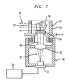
- Fig. 7 is a cross-sectional view showing an exemplary laser transmitter as depicted in Figs. 5-6.
- Fig. 8 is a schematic block diagram of a laser beam processing unit on a Rover station.
- Figs. 9A through 9J are illustrations of exemplary emission patterns of laser beams generated by a laser transmitter.
- Fig. 10 is a schematic diagram showing an elevation angle as measured between a Base station laser transmitter and a reference point on a Rover station.
- Fig. 11 is a schematic illustration showing estimated Rover positions constrained to belong to a conical surface generated from a measured elevation angle when estimating floating and integer ambiguity.
- Fig. 12 is a flow chart for generating integer and floating point corrections based on an elevation angle and geometric surface as depicted in Figs. 10-11.
- a typical exemplary position navigation system for implementing the features of the invention includes multiple satellites each radiating signals in two frequency bands: the L1 band and the L2 band.
- Two carrier signals are simultaneously transmitted in the L1-band; both carrier signals have the same frequency, but are shifted in phase by ⁇ /2 (90°).
- the first L1 carrier signal is modulated by the clear acquisition C/A-code signal and the second L1 carrier signal is modulated by the precision P-code signal.
- One carrier signal is transmitted in the L2 band, and uses a different frequency than the L1 carrier signals.
- the L2 carrier signal is modulated by the same P-code signal used to modulate the second L1 carner signal. These carrier frequencies are between 1 GHz and 2 GHz in value.
- Each C/A-code signal and P-code signal comprises a repeating sequence of segments, or "chips", where each chip is of a predetermined time period and has a pre-selected value, which is either +1 or -1.
- the segment values follow a pseudo-random pattern, and thus the C/A-codes and the P-codes are called pseudo-random code signals, or PR-code signals.
- each code signal is modulated by a low frequency (50 Hz) information signal (so-called information symbols).
- the approximate distance between a satellite and a receiver is equal to the speed of light multiplied by the transmission time it takes the satellite signal to reach the receiver. This approximate distance is called the pseudo-range, and it can be corrected for certain errors to find a corrected distance between the satellite and the receiver.
- the transmission time from satellite to receiver is measured with the aid of clocks in the receiver and the satellite, and with the aid of several time scales (i.e., timing marks) present within the received satellite signal.
- the clocks in the satellites and the receiver are set to substantially the same time, but it is assumed that the receiver clock has a time offset because the receiver clock is based upon a quartz-crystal whereas each satellite clock is based upon a more accurate atomic reference clock.
- the receiver has the orbital patterns of the satellites stored in a memory, and it can determine the orbital position of the satellites based on the time of its clock.
- the receiver reads the timing marks on the satellite's signal, and compares them against it own clock to determine the transmission time from satellite to receiver.
- the satellite's low-frequency (e.g., 50Hz) information signal provides the least precise timing information
- the C/A-code signal provides the next most precise timing information
- the P-code signal provides the most precise timing information.
- the pseudo-range is determined from the low-frequency information signal and the C/A-code signal for civilian users and some military users, and is determined from the low-frequency information signal and the P-code signal for most military users. Accurate use of the P-code signal requires knowledge of a certain code signal that is only known to military users. Better precision than that provided by the P-code signal can be obtained by measuring the phase of the satellite carrier signal in a differential navigation DN mode using two receivers.
- Fig. 1 shows a schematic drawing of an exemplary differential navigation system incorporating certain features of the present invention.
- the differential navigation system includes a Rover GPS unit 110 and a Base GPS Unit 114.
- the location of the Base 114 is known and the system is attempting to determine the location of the Rover 110.
- Rover 110 receives signals from satellites 102, 104, 106, 108 via antenna 112.
- Base 114 receives signals from satellites 102, 104, 106, 108 via antenna 116.
- the Base 114 transmits differential correction signals to the Rover 110 via communication channel 118.
- Communication channel 118 may be, for example, a wired or wireless connection.
- a laser unit 120 associated with Base 114 transmits laser beam(s) 122 to an optical sensor 124 on the Rover 110 in order to precisely measure an elevation angle 126 between reference points on the Base and Rover.
- a local reference plane such as 128 is used for measuring the elevation angle. Additional details regarding the generation, transmission, detection and analysis of laser signals to measure the elevation angle are recited below in connection with Figs. 5-9.
- the Rover unit 110 is modified to add the functionality of an integer ambiguity module in order to resolve integer ambiguities based at least in part on the measurement of elevation angle 126.
- a high level block diagram of a satellite receiver configured in accordance with one embodiment of the invention is shown in Fig. 2.
- Fig. 2 shows a satellite receiver unit 202 comprising a signal receiver 204 for receiving satellite signals via antenna 212.
- the signal receiver 204 provides signal measurements to the navigation location determining module 206.
- the navigation location determining module 206 performs the function of determining the location of the satellite receiver unit 202 using the measurements received from signal receiver 204. This function is sometimes referred to as the navigation task.
- the satellite receiver unit 202 also includes a communication interface 208 for communicating with other devices via a communication channel.
- satellite receiver unit 202 receives information from the Base station via the communication interface 208.
- the satellite receiver unit 202 also contains an integer ambiguity module 210 for operating in accordance with the principles of the present invention.
- Fig. 2 is meant to show a high level functional block diagram of a satellite receiver unit for purposes of illustrating the principles of the present invention.
- a typical satellite receiver unit would include one or more processors for controlling the overall functioning of the unit. Such processors generally operate under the control of stored computer program code stored in a memory unit of the unit. Given the description herein, one skilled in the art would readily understand how to modify a well known satellite receiver unit in order to implement the principles of the present invention.
- the term receiver refers to both the GPS satellite receiver unit 202 and the signal receiver 204 which is part of the satellite receiver unit 202.
- the satellite receiver unit 202 refers to the general unit used by a user to perform location functions by receiving and processing satellite signals
- the signal receiver 204 refers to a particular portion of the satellite receiver unit 202 which is a signal processing unit which receives signals via the antenna 212 and processes the signals (as described herein below) and sends certain signal measurements and parameters to the navigation location determining module for performance of the navigation task.
- Fig. 3 shows a high level block diagram of a satellite receiver 200 in accordance with one embodiment of the invention. It is noted that the block diagrams used herein are meant to describe the high level functioning and configuration of a unit. One skilled in the art would readily recognize that some of the blocks represent hardware components while other blocks represent some function or operation. The functions and operations may be performed by hardware circuits, software instructions executing on a processor, firmware, or some combination of hardware and software. Given the description herein, those skilled in the art would be able to implement the described functionality using well known and various combinations of hardware and software. As such, implementation details of the functions described herein will not be described in detail as such implementation details would be readily known to one skilled in the art.
- satellite receiver 200 comprises an antenna 214 for receiving satellite signals 216.
- RF cable 222 carries satellite signals from the antenna to RF module 218.
- RF module 218 amplifies, frequency converts, and filters the signal in a manner well known in the art.
- the signal output from the RF module 218 has low carrier frequency and sufficient power for analog to digital conversion.
- the output of the RF module 218 is provided to an analog-to-digital converter (ADC) 220, where the signal in each satellite channel is quantized by level and digitized by time.
- ADC 220 provides the digital signal to individual satellite channel processors 226, 228, 230.
- the output of the satellite channel processors is provided to a navigation processor 232 which performs the navigation task.
- each channel tracks a selected one of the satellite signals.
- Each tracking channel measures the delay of one PR-code signal within the satellite signal (e.g., C/A-code or P-code signal), and also the phase of the down-converter version of the satellite's carrier signal.
- a typical tracking channel comprises a Delay-Lock Loop (DLL) circuit for tracking the delay of the PR-code, a Phase-Lock Loop (PLL) circuit for tracking the phase of the satellite's carrier signal, and three correlators which generate the input signals for the DLL and PLL circuits.
- DLL Delay-Lock Loop
- PLL Phase-Lock Loop
- the DLL circuit has a reference code generator that generates a set of reference code signals, each of which tracks the PR-code of the satellite signal, and each of which is provided as an input to a respective correlator. Each correlator output is representative of the degree to which the reference code signals are tracking the satellite code signal (i.e., the amount by which the reference signals are advanced or retarded in time with respect to the satellite signal).
- the DLL circuit also has a DLL discriminator and a DLL filter.
- the DLL discriminator receives inputs from two correlators, a DLL correlator that generates a base signal for controlling the DLL circuit and a main correlator that generates a signal useful for normalizing the base signal from the DLL correlator.
- the DLL discriminator generates an error control signal from these inputs; this error signal is filtered by the DLL filter before being provided to the DLL reference code generator as a control signal.
- the value of the DLL error signal varies by the amount that the reference code signals of the DLL generator are delayed or advanced with respect to the satellite code signal being tracked, and causes the code generator to adjust the timing of the reference code signals to better match the satellite's code signal. In this manner, tracking is achieved.
- the pseudo-range 240 may be generated by methods known to the art from the receiver clock 242, the 50 Hz information signal 244, and any one of the reference code signals 246 generated by the DLL.
- the PLL has a reference carrier generator that generates a reference carrier signal which tracks the down-converter version of the satellite's carrier signal.
- a reference carrier generator that generates a reference carrier signal which tracks the down-converter version of the satellite's carrier signal.
- the frequency of the reference carrier signal is fNCO since the reference carrier frequency is often generated by a numerically-controlled oscillator within the reference carrier generator.
- the PLL circuit also has a PLL discriminator and a PLL filter.
- the PLL discriminator receives inputs from two correlators, a PLL correlator that generates a base signal for controlling the PLL circuit, and the main correlator that generates a signal useful for normalizing the base signal from the PLL correlator.
- Each correlator output is representative of the degree to which the reference carrier signal is tracking the satellite's carrier signal (i.e., the amount by which the reference carrier signal is advanced or retarded in time with respect to the satellite's carrier signal).
- the PLL discriminator generates an error control signal from these inputs; this error control signal is filtered by the PLL filter before being provided to the PLL reference carrier generator as a control signal.
- the value of the PLL error signal varies by the amount that the reference carrier signal of the PLL reference carrier generator is delayed or advanced with respect to the satellite carrier signal being tracked, and causes the reference carrier generator to adjust the timing of the reference carrier signal to better match the satellite's carrier signal.
- the reference carrier generator provides a phase input 250 representative of the phase (integrated frequency) of the PLL reference oscillator.
- This phase input signal 250 may be combined with other information to provide a final output signal 252 representative of the full phase of the satellite signal (but with ambiguities in it).
- each individual tracking channel usually comprises a search system 254 which initially varies the reference signals to bring the PLL and DLL circuits into lock mode.
- search system 254 which initially varies the reference signals to bring the PLL and DLL circuits into lock mode.
- the PLL loop can easily track the Doppler-shift frequency of the carrier signal, which is in the kHz range.
- the satellite transmits at a fixed frequency, but the relative motion between the satellite and receiver causes the frequency seen by the receiver to be slightly shifted by the Doppler frequency.
- the reference oscillator (e.g., NCO) of the PLL circuit tracks the frequency of a selected one of the down-converted satellite signals. As a result, it inherently tracks the Doppler-shift frequency of the satellite's carrier signal.
- the features of the invention can be implemented in many application environments and operational modes.
- the invention is suitable for both the real-time processing mode (RTP) and for the post-processing mode (PP). It is useful in general application areas where the relative positions between Rover and Base stations can be varied in all directions (X, Y and Z axes). It is also applicable to more limited environments such as where a Base station is always in a fixed position, or where a Rover is mounted on a vehicle or on excavation equipment, etc.
- the laser unit 120 and optical sensor 124 of Fig. 1 are shown in exemplary embodiments of the invention in Figs. 5 and 6.
- a rotary laser device 27 projects a plurality of beams by rotary irradiation to a photodetection sensor device 28.
- a tripod 29 installed for approximate alignment with a known point X supports the laser device 27.
- the tripod 29 carries a GPS measuring device 75 and constitutes a Base station..
- a Rover is shown as a mobile rod 34 that carries the sensor device 28.
- a GPS measuring device 30 is mounted an upper end of the rod 34 and provides positional information based on signals received from a satellite.
- the laser beam preferably incorporates fan-shaped beams 33a and 33b in a vertical direction and a fan-shaped beam 33c tilted diagonally with respect to the other two beams 33a, 33b forming an N-shaped configuration. It is not required that the fan-shaped beams 33a and 33b run in vertical directions, although detection and analysis may be benefited where they run parallel to each other and perpendicularly cross a horizontal reference plane.
- the Rover is mounted on excavation equipment such as earth mover 17 with a blade 18 having a scraping edge 18a located at a predetermined height.
- the rotary laser device 27 includes a laser projector 36 having a projection optical axis 40.
- the laser projection 36 is accommodated in the casing 35 for tilting at any angle.
- a rotator 32 is rotatably mounted on an upper portion of the laser projector 36, and a pentagonal prism 39 is mounted on the rotator 32.
- a motor drives the rotator through a scanning gear 41.
- a laser beam emitting unit 52 and a collimator lens 53 are arranged on a projection optical axis 40 together forming a projecting optical system 54.
- the rotator 32 includes a prism holder 55 supporting the prism 39 and a diffraction grating 56.
- the laser beam 33 emitted from the laser beam emitting unit 52 is turned to a parallel luminous flux by the collimator lens 53 and enters the diffraction grating 56.
- the incident laser beam 33 is divided by the diffraction grating 56 so as to form a plurality of fan-shaped laser beams such as 33a, 33b, 33c that are deflected in a horizontal direction by the pentagonal prism 39 and are projected through a projection window 57 of the prism holder 55.
- the characteristics of the laser beam are controlled by a control unit 50.
- multiple laser beams generate from a laser transmitter may be utilized in practicing the invention such as beams respectively having different characteristics such as different frequencies, different polarizations, different wavelengths, different geometric forms, and/or different intensities.
- a photodetection unit 62 for detecting the fan-shaped beams 33a, 33b, 33c is mounted on the photodetection sensor device 28.
- the photodetection sensor device 28 includes display unit 63, alarm unit 64, and input unit 65, as well as storage unit 66, arithmetic unit 67, photodetection signal processing circuit 68, photodetection signal output unit 59 and tilt detector 70 for detecting the tilting of rod 34.
- Figs. 9A through 9J it will be understood by those skilled in the art that various beam patterns and variations analogous to an N-shaped laser signal can be used as a basis for sensing multiple diverging laser beams and computing an elevation angle between a reference point on a Base station and a corresponding reference point on a Rover. Some of these patterns incorporate only two fan-shaped beams (see Figs. 9A-9B) while others incorporate three or more fan-shaped beams (see Figs. 9C-9J). Also, patterns incorporating curved or creased fan-shaped beams (see Figs. 9I-9J) can also be used.
- Exemplary techniques for detecting and computing elevation angles including the technique of using two separated light receiving sections in an optical sensor 28 for analyzing two selected fan-shaped beams are disclosed in U.S. Patent Application Publication No. US 2003/0136901 A1 published July 24, 2003 entitled POSITION DETERMINING APPARATUS AND ROTARY LASER APPARATUS USED WITH THE SAME.
- the invention provides Rover elevation angle theta measurements that are synchronized with GPS and GLONASS navigational data.
- the elevation angle is measured between a local horizon plane 90 and the central line 92 of the laser N-beam 94 emitted by the transmitter 27 and detected at the optical lens center of the sensor 28.
- the optical center of the sensor lens 95 is at a fixed distance with respect to the antenna phase center of the GPS Rover.
- the state vector Y k or Y k consists of x,y,z of correction ⁇ X , the time scales shift ⁇ t, and ambiguity.
- the geometric surface generated from the elevation angle theta is a cone with the vertex in the transmitter centerline point and a conical surface generated to be inclined to the local horizon by the angle theta measured by the sensor. If the Rover is at a higher elevation than the laser transmitter, the conical surface expands upwardly as shown in Fig. 11. Alternatively if the Rover is at a lower elevation than the laser transmitter, the conical surface expands downwardly. Possible antenna locations are indicated at 96, 97, 98, and 99 on the surface of the cone. Such locations can be anywhere on the conical surface - however the computation of the two additional degrees of freedom such as two additional polar coordinates will ultimately confirm that only one of the possible reference points represents the correct integer ambiguity.
- This geometric information is useful for the process of ambiguity fixing because it effectively restricts the region where the integer ambiguity may belong.
- Using this additional geometry constraint when estimating floating and resolving integer ambiguities makes it possible to better average GPS noise and finally to initialize faster and determine more rapidly and efficiently a baseline vector between the Base and Rover.
- the ambiguity resolution task generally comprises the following three main parts:
- the present invention pertains to estimating and resolving both the integer ambiguities and the floating ambiguities.
- the apparatus and methods of our present invention use as an input data:
- the following recitation of data processing operations provides an explanation of the underlying computational operations in an exemplary implementation and embodiment of the invention.
- the mathematical analysis describes how the geometry constraint may be incorporated into the floating and fixed (i.e., integer) carrier phase ambiguity estimation schemes, provided the floating ambiguity estimation is performed recursively and either the normal system matrix or inverse of the covariance matrix of unknown parameters is available.
- the normal system matrix is denoted as D k below in the formula (1).
- the augmented matrix is denoted as D k in (7). Augmentation results from application of the constraint (4).
- the augmented scheme of estimating floating ambiguities comprising using the Laser Elevation Angle data in the numerical process will consist in making one or more Newton iterations to minimize the nonlinear function P ( Y ) in (6).
- the numerical scheme above is formulated in the general form. It may be used independently of the specifics of the ambiguity estimation algorithm used in recursive estimation.
- the formulae (6), (7) express how to add one step of the Newton method to the ambiguity estimation scheme.
- the Newton method aims to minimize the penalty function (5) in the course of floating ambiguities estimation.
- the floating point ambiguity estimation goes first before the integer ambiguity estimation.
- the augmented matrix D and k and current floating ambiguity estimation may be used the usual way when performing the integer ambiguity search.
- both Lenstra-Lenstra-Lovasz transformation and ⁇ -decorrelation may be applied to the augmented matrix D and k .
- the observation vector consists of all navigation parameters comprising between satellites and Rover and between satellites and Base pseudo-ranges and carrier phases.
- the observation vector is involved into calculation of the right-hand side vector R k in the equation (1) above.
- the state vector consists of all unknowns to be estimated: X,Y,Z of the Rover, clock shift, ambiguity for all satellites and frequency bands. More precisely: X,Y,Z of the Rover, between Rover and Base clock shift, between Base and Rover difference of ambiguity for all satellites and frequency bands.
- the state vector estimated at the epoch k is denoted by Y k in the equation (1) above.
- the present invention does not replace or eliminate the "rounding of the float ambiguity vector to the nearest set of integers".
- the term 'rounding off' depends on the norm one uses to measure the closeness of two vectors - floating and integer ambiguity in our case.
- the integer ambiguity resolution, or rounding off may be considered as a solution to the problem: where N is the floating ambiguity vector, Z is the integer valued n-dimensional space (or integer lattice), N is the integer-valued vector of ambiguity to be found, ⁇ stands for the norm we use to measure the closeness between two vectors N and N .
- the present invention (as part of integer ambiguity resolution) replaces the matrix D with the augmented matrix D and , where the matrix D appears in the equation (1), the matrix D and is defined in the equation (8). Also the floating point vector N as part of the state vector Y k in (1) is replaced with the part of the state vector Y and k in (7).]
- the various steps for implementing the method of operation for an exemplary embodiment in a differential navigation system are shown.
- the invention provides a unique technique for collecting and processing various data parameters in order to generate spatial coordinates that identify the unknown Rover locations with as much precision as possible.
- the estimation and resolution of carrier wave ambiguities is an important part of this data collection, calculation and processing.
- laser beams transmitted from a known location such as a Base station are received by a rover sensor (step 302) and analyzed (step 304) in order to determine an elevation angle of the laser beams relative to a local horizon reference (step 306).
- This elevation angle is used to create a geometric conical surface (step 308) that provides a geometric constraint for estimating carrier phase ambiguities sent by the navigational satellites.
- a penalty term is calculated in accordance with equation (5) using the elevation angle, current Rover position, and transmitter position (step 210).
- An augmented normal system matrix (8) is calculated (step 312) and then used along with input 316 to calculate an augmented right hand side vector for (7) (step 314).
- the input 316 is generated by a series of steps incorporating data from both a Base station and the Rover that can proceed separately and independently from the laser beam detection and analysis.
- satellite carrier signals are received (step 320) and processed to generate pseudo-range (step 322) and carrier phase (step 324) parameters for further processing such as at the Rover (step 326).
- Analogous events occur for satellite carrier signals received by the Rover (steps 328, 330, 332).
- the combined data imputs from both Base and Rover is used to compute single differences of pseudo-range and carrier phase data for each satellite (step 334). Additional calculations are made for satellite positions (step 336) and for distances between satellites and both receivers (step 338). It is then possible to calculate single differences residuals involving pseudo-ranges (step 340) and carrier phases (step 342) which are both used for calculating right hand side vector (step 344) of equation (1).
- step 346 calculates single recursion by formula (7) to estimate floating position of the rover, clock difference, and floating ambiguity.
- ambiguity resolution steps 348, 350
- a final fixed position of the Rover is estimated (step 362).
- the normal system matrix is updated (step 364) according to the formula (2) and the sequence (step 368) starts all over again.
- the geometry constraint (4) (which means 'to belong to the cone surface') is used periodically as a part of recursive process (7) and every time there is a necessity to resolve ambiguity or solve the problem (MP) above. Preferred finishing of this process is registered by appearance of the signal of integer ambiguities resolution, which indicates that ambiguity resolution was performed sufficiently safely.
- the integer ambiguity estimations incorporating the features of the present invention together with other input data are used for accurate determination of the baseline vector between the Base and the Rover.
- the baseline vector is a three dimensional Rover - Base difference of X,Y,Z.
- the above method of the present invention may be carried out in an integer ambiguity module 210 (see Fig. 2) or by data processor means located on a receiver or located remotely using hardware, software, firmware, or combinations thereof.
- Program instructions implementing the invention may also be stored on disk, tape, non-volatile memory, volatile memory, or other forms of computer readable medium. In view of the detailed disclosure herein, it is well within the ability of one skilled in the GPS art to make, implement and use the present invention.
Landscapes
- Engineering & Computer Science (AREA)
- Radar, Positioning & Navigation (AREA)
- Remote Sensing (AREA)
- Physics & Mathematics (AREA)
- General Physics & Mathematics (AREA)
- Computer Networks & Wireless Communication (AREA)
- Electromagnetism (AREA)
- Position Fixing By Use Of Radio Waves (AREA)
- Radio Relay Systems (AREA)
Applications Claiming Priority (2)
| Application Number | Priority Date | Filing Date | Title |
|---|---|---|---|
| US10/810,247 US7002513B2 (en) | 2004-03-26 | 2004-03-26 | Estimation and resolution of carrier wave ambiguities in a position navigation system |
| US810247 | 2004-03-26 |
Publications (4)
| Publication Number | Publication Date |
|---|---|
| EP1580570A2 true EP1580570A2 (fr) | 2005-09-28 |
| EP1580570A3 EP1580570A3 (fr) | 2006-09-27 |
| EP1580570B1 EP1580570B1 (fr) | 2013-06-19 |
| EP1580570B8 EP1580570B8 (fr) | 2013-08-21 |
Family
ID=34862104
Family Applications (1)
| Application Number | Title | Priority Date | Filing Date |
|---|---|---|---|
| EP05002792.9A Expired - Lifetime EP1580570B8 (fr) | 2004-03-26 | 2005-02-10 | Estimation et résolution d'ambiguités d'onde porteuse dans un système de position et de navigation |
Country Status (4)
| Country | Link |
|---|---|
| US (2) | US7002513B2 (fr) |
| EP (1) | EP1580570B8 (fr) |
| JP (1) | JP2005283576A (fr) |
| CA (1) | CA2494417C (fr) |
Cited By (7)
| Publication number | Priority date | Publication date | Assignee | Title |
|---|---|---|---|---|
| WO2007089767A3 (fr) * | 2006-01-31 | 2007-10-11 | Navcom Tech Inc | Procédé pour l'utilisation combinée d'un système de positionnement local, d'un système local de cinématique en temps réel (rtk) et d'un système de positionnement à phase de porteuse régional, longue portée ou mondial |
| US7679555B2 (en) | 2004-01-13 | 2010-03-16 | Navcom Technology, Inc. | Navigation receiver and method for combined use of a standard RTK system and a global carrier-phase differential positioning system |
| EP2378031A4 (fr) * | 2009-12-25 | 2011-12-07 | Hunan Sany Intelligent Control | Procede et dispositif de positionnement de systeme support de bras et camion de pompe a beton |
| US8883960B2 (en) | 2007-01-04 | 2014-11-11 | Sk Chemicals Co., Ltd. | Polyarylene sulfide resin with excellent luminosity and preparation method thereof |
| US8983685B2 (en) | 2010-07-30 | 2015-03-17 | Deere & Company | System and method for moving-base RTK measurements |
| CN111829492A (zh) * | 2020-07-24 | 2020-10-27 | 中交第二航务工程局有限公司 | 基于激光垂准仪应用的联系测量方法 |
| US12471055B2 (en) * | 2023-06-29 | 2025-11-11 | Here Global B.V. | Methods and apparatuses for high-precision positioning using floating clock models |
Families Citing this family (56)
| Publication number | Priority date | Publication date | Assignee | Title |
|---|---|---|---|---|
| US8271194B2 (en) * | 2004-03-19 | 2012-09-18 | Hemisphere Gps Llc | Method and system using GNSS phase measurements for relative positioning |
| US8686900B2 (en) | 2003-03-20 | 2014-04-01 | Hemisphere GNSS, Inc. | Multi-antenna GNSS positioning method and system |
| US8140223B2 (en) | 2003-03-20 | 2012-03-20 | Hemisphere Gps Llc | Multiple-antenna GNSS control system and method |
| US8634993B2 (en) | 2003-03-20 | 2014-01-21 | Agjunction Llc | GNSS based control for dispensing material from vehicle |
| US8190337B2 (en) | 2003-03-20 | 2012-05-29 | Hemisphere GPS, LLC | Satellite based vehicle guidance control in straight and contour modes |
| US9002565B2 (en) | 2003-03-20 | 2015-04-07 | Agjunction Llc | GNSS and optical guidance and machine control |
| US8583315B2 (en) | 2004-03-19 | 2013-11-12 | Agjunction Llc | Multi-antenna GNSS control system and method |
| US8705022B2 (en) * | 2004-07-13 | 2014-04-22 | Trimble Navigation Limited | Navigation system using both GPS and laser reference |
| US7228230B2 (en) * | 2004-11-12 | 2007-06-05 | Mitsubishi Denki Kabushiki Kaisha | System for autonomous vehicle navigation with carrier phase DGPS and laser-scanner augmentation |
| US8401503B2 (en) * | 2005-03-01 | 2013-03-19 | Qualcomm Incorporated | Dual-loop automatic frequency control for wireless communication |
| US8009775B2 (en) * | 2005-03-11 | 2011-08-30 | Qualcomm Incorporated | Automatic frequency control for a wireless communication system with multiple subcarriers |
| US7522099B2 (en) * | 2005-09-08 | 2009-04-21 | Topcon Gps, Llc | Position determination using carrier phase measurements of satellite signals |
| US7706976B1 (en) * | 2006-07-26 | 2010-04-27 | Trimble Navigation, Ltd. | Position based velocity estimator |
| CN101512376B (zh) * | 2006-09-19 | 2013-05-08 | 诺基亚公司 | 相对定位 |
| USRE48527E1 (en) | 2007-01-05 | 2021-04-20 | Agjunction Llc | Optical tracking vehicle control system and method |
| US8311696B2 (en) | 2009-07-17 | 2012-11-13 | Hemisphere Gps Llc | Optical tracking vehicle control system and method |
| WO2008124657A1 (fr) * | 2007-04-05 | 2008-10-16 | Power Curbers, Inc. | Procédés et systèmes utilisant un contrôle 3d pour définir un chemin de fonctionnement pour une machine de construction |
| US20090189805A1 (en) * | 2008-01-25 | 2009-07-30 | Bruno Sauriol | Low Cost Instant RTK Positioning System and Method |
| US9002566B2 (en) | 2008-02-10 | 2015-04-07 | AgJunction, LLC | Visual, GNSS and gyro autosteering control |
| ES2413064T3 (es) * | 2008-04-22 | 2013-07-15 | Deutsches Zentrum für Luft- und Raumfahrt e.V. | Procedimiento para un sistema de navegación global por satélite |
| WO2010021658A2 (fr) * | 2008-08-19 | 2010-02-25 | Trimble Navigation Limited | Procédés de traitement de signaux de système de navigation par satellites et appareil d’interruption de poursuite |
| CN102246258B (zh) | 2008-10-12 | 2015-09-02 | Fei公司 | 用于局部区域导航的高精确度射束放置 |
| US8781219B2 (en) | 2008-10-12 | 2014-07-15 | Fei Company | High accuracy beam placement for local area navigation |
| US8018377B2 (en) * | 2009-01-23 | 2011-09-13 | Her Majesty The Queen In Right Of Canada As Represented By The Minister Of Natural Resources | Decoupled clock model with ambiguity datum fixing |
| US8401704B2 (en) | 2009-07-22 | 2013-03-19 | Hemisphere GPS, LLC | GNSS control system and method for irrigation and related applications |
| US8174437B2 (en) * | 2009-07-29 | 2012-05-08 | Hemisphere Gps Llc | System and method for augmenting DGNSS with internally-generated differential correction |
| US8334804B2 (en) | 2009-09-04 | 2012-12-18 | Hemisphere Gps Llc | Multi-frequency GNSS receiver baseband DSP |
| US8548649B2 (en) | 2009-10-19 | 2013-10-01 | Agjunction Llc | GNSS optimized aircraft control system and method |
| US20110116386A1 (en) * | 2009-11-16 | 2011-05-19 | General Dynamics C4 Systems, Inc. | Transmission control in a wireless communication system |
| DE102009059106A1 (de) | 2009-12-18 | 2011-06-22 | Wirtgen GmbH, 53578 | Selbstfahrende Baumaschine und Verfahren zur Steuerung einer selbstfahrenden Baumaschine |
| US8583326B2 (en) | 2010-02-09 | 2013-11-12 | Agjunction Llc | GNSS contour guidance path selection |
| EP2612342B1 (fr) | 2010-08-31 | 2018-08-22 | FEI Company | Navigation et traitement d'échantillons à l'aide d'une source d'ions contenant des espèces à masse faible et à masse élevée |
| DE102010060654A1 (de) * | 2010-11-18 | 2012-05-24 | Status Pro Maschinenmesstechnik Gmbh | Verfahren zum Vermessen einer Oberfläche eines Bauteiles oder Bauwerkes |
| JP6108684B2 (ja) * | 2011-06-08 | 2017-04-05 | エフ・イ−・アイ・カンパニー | 局所領域ナビゲーション用の高精度ビーム配置 |
| DE102012001289A1 (de) | 2012-01-25 | 2013-07-25 | Wirtgen Gmbh | Selbstfahrende Baumaschine und Verfahren zum Steuern einer selbstfahrenden Baumaschine |
| US8989968B2 (en) | 2012-10-12 | 2015-03-24 | Wirtgen Gmbh | Self-propelled civil engineering machine system with field rover |
| US9096977B2 (en) | 2013-05-23 | 2015-08-04 | Wirtgen Gmbh | Milling machine with location indicator system |
| JP6302630B2 (ja) * | 2013-06-14 | 2018-03-28 | 株式会社トプコン | Rtk測量作業に用いる準備システム |
| CN104700592A (zh) * | 2013-12-06 | 2015-06-10 | 上海诺司纬光电仪器有限公司 | 一种扫平仪控制系统 |
| EP2985631B1 (fr) * | 2014-08-14 | 2019-08-07 | Trimble Inc. | Positionnement par un système de navigation par satellite impliquant la génération d'informations de correction spécifiques au récepteur ou spécifiques au type de récepteur |
| DE102014012825A1 (de) | 2014-08-28 | 2016-03-03 | Wirtgen Gmbh | Selbstfahrende Baumaschine und Verfahren zur Steuerung einer selbstfahrenden Baumaschine |
| DE102014012831B4 (de) | 2014-08-28 | 2018-10-04 | Wirtgen Gmbh | Selbstfahrende Baumaschine und Verfahren zum Steuern einer selbstfahrenden Baumaschine |
| DE102014012836B4 (de) | 2014-08-28 | 2018-09-13 | Wirtgen Gmbh | Selbstfahrende Baumaschine und Verfahren zur Visualisierung des Bearbeitungsumfeldes einer sich im Gelände bewegenden Baumaschine |
| US10330792B2 (en) * | 2016-09-14 | 2019-06-25 | Qualcomm Incorporated | Repair of carrier-phase cycle slips using displacement data |
| CN106646365B (zh) * | 2016-11-25 | 2024-02-20 | 北京凌宇智控科技有限公司 | 一种定位基站、定位系统及定位方法 |
| DE102018119962A1 (de) | 2018-08-16 | 2020-02-20 | Wirtgen Gmbh | Selbstfahrende Baumaschine und Verfahren zum Steuern einer selbstfahrenden Baumaschine |
| CN110207720B (zh) * | 2019-05-27 | 2022-07-29 | 哈尔滨工程大学 | 一种极区组合导航的自适应双通道校正方法 |
| CN112014862B (zh) * | 2019-05-30 | 2024-03-29 | 上海海积信息科技股份有限公司 | 一种载波相位观测数据生成方法及装置 |
| DE102019118059A1 (de) | 2019-07-04 | 2021-01-07 | Wirtgen Gmbh | Selbstfahrende Baumaschine und Verfahren zum Steuern einer selbstfahrenden Baumaschine |
| US12196554B2 (en) * | 2019-10-24 | 2025-01-14 | Javad Gnss, Inc. | Integrated GNSS and optical system |
| CN113840321B (zh) * | 2020-06-24 | 2024-01-30 | 大唐移动通信设备有限公司 | 一种信息指示方法、装置及通信设备 |
| DE102020213769A1 (de) * | 2020-11-02 | 2022-05-05 | Robert Bosch Gesellschaft mit beschränkter Haftung | Verfahren zum Auswerten mindestens eines GNSS-Satellitensignals mit Mehrdeutigkeitsauflösung |
| CN113419263A (zh) * | 2021-05-25 | 2021-09-21 | 武汉导航与位置服务工业技术研究院有限责任公司 | 一种分离模糊度与位置解算的方法 |
| CN117413205A (zh) * | 2021-06-08 | 2024-01-16 | 三菱电机株式会社 | 定位装置和定位方法 |
| CN113608427B (zh) * | 2021-07-09 | 2022-07-05 | 中国科学院国家授时中心 | 一种集中式天基时间基准建立方法 |
| CN120722405A (zh) * | 2025-08-13 | 2025-09-30 | 博睿泰克科技(宁波)有限公司 | 基于多信号源协同的复杂环境高精度定位系统 |
Citations (4)
| Publication number | Priority date | Publication date | Assignee | Title |
|---|---|---|---|---|
| US5471218A (en) | 1993-07-01 | 1995-11-28 | Trimble Navigation Limited | Integrated terrestrial survey and satellite positioning system |
| US6268824B1 (en) | 1998-09-18 | 2001-07-31 | Topcon Positioning Systems, Inc. | Methods and apparatuses of positioning a mobile user in a system of satellite differential navigation |
| US20030136901A1 (en) | 2002-01-21 | 2003-07-24 | Fumio Ohtomo | Position determining apparatus and rotary laser apparatus used with the same |
| US20030137658A1 (en) | 2002-01-21 | 2003-07-24 | Fumio Ohtomo | Construction machine control system |
Family Cites Families (16)
| Publication number | Priority date | Publication date | Assignee | Title |
|---|---|---|---|---|
| US2352442A (en) * | 1940-05-23 | 1944-06-27 | Loewy Eng Co Ltd | Straightening machine for metal bars |
| US2487973A (en) * | 1945-07-16 | 1949-11-15 | Hydropress Inc | Metal bar straightening machine |
| US2487972A (en) * | 1945-07-16 | 1949-11-15 | Hydropress Inc | Metal bar straightening machine |
| US2715431A (en) * | 1952-10-24 | 1955-08-16 | Lombard Corp | Combined tensioning and twisting apparatus for straightening extruded shapes |
| JPS54139784A (en) * | 1978-04-21 | 1979-10-30 | Ngk Insulators Ltd | Method and device for testing ceramic piece having innumerable through pores |
| US4906170A (en) * | 1988-02-16 | 1990-03-06 | Cello-O-Core | Apparatus for printing on plastic tubing |
| JP3208493B2 (ja) * | 1991-04-02 | 2001-09-10 | 株式会社ブリヂストン | パイプコンベヤにおける捩れ矯正装置 |
| US5205991A (en) * | 1991-07-30 | 1993-04-27 | Corning Incorporated | Manufacture of extruded ceramics |
| US5189424A (en) * | 1991-09-19 | 1993-02-23 | Environmental Research Institute Of Michigan | Three dimensional interferometric synthetic aperture radar terrain mapping employing altitude measurement and second order correction |
| JP2748220B2 (ja) * | 1993-08-23 | 1998-05-06 | 株式会社イナックス | 衛生陶器成形物の脱型及び仕上処理方法 |
| US5431866A (en) * | 1994-01-27 | 1995-07-11 | Phillips Petroleum Company | Method and apparatus for positioning a pipe |
| US5935194A (en) * | 1994-02-18 | 1999-08-10 | Trimble Navigation Limited | Method for using external constraints to improve the speed and reliability of phase ambiguity resolution in real-time kinematic initialization |
| US5519620A (en) * | 1994-02-18 | 1996-05-21 | Trimble Navigation Limited | Centimeter accurate global positioning system receiver for on-the-fly real-time kinematic measurement and control |
| US6433866B1 (en) * | 1998-05-22 | 2002-08-13 | Trimble Navigation, Ltd | High precision GPS/RTK and laser machine control |
| JP4121642B2 (ja) * | 1998-11-13 | 2008-07-23 | 株式会社トプコン | 建設機械制御システム |
| JP2003232845A (ja) * | 2002-02-12 | 2003-08-22 | Furuno Electric Co Ltd | 移動体の方位および姿勢検出装置 |
-
2004
- 2004-03-26 US US10/810,247 patent/US7002513B2/en not_active Expired - Lifetime
-
2005
- 2005-01-25 CA CA2494417A patent/CA2494417C/fr not_active Expired - Fee Related
- 2005-02-10 EP EP05002792.9A patent/EP1580570B8/fr not_active Expired - Lifetime
- 2005-03-14 JP JP2005070471A patent/JP2005283576A/ja active Pending
- 2005-07-13 US US11/180,507 patent/US7221314B2/en not_active Expired - Lifetime
Patent Citations (4)
| Publication number | Priority date | Publication date | Assignee | Title |
|---|---|---|---|---|
| US5471218A (en) | 1993-07-01 | 1995-11-28 | Trimble Navigation Limited | Integrated terrestrial survey and satellite positioning system |
| US6268824B1 (en) | 1998-09-18 | 2001-07-31 | Topcon Positioning Systems, Inc. | Methods and apparatuses of positioning a mobile user in a system of satellite differential navigation |
| US20030136901A1 (en) | 2002-01-21 | 2003-07-24 | Fumio Ohtomo | Position determining apparatus and rotary laser apparatus used with the same |
| US20030137658A1 (en) | 2002-01-21 | 2003-07-24 | Fumio Ohtomo | Construction machine control system |
Non-Patent Citations (1)
| Title |
|---|
| BRADFORD W. PARKINSON; JAMES J. SPILKER JR.: "Progress In Astronautics and Aeronautics", vol. 163, 1996, AMERICAN INSTITUTE OF AERONAUTICS AND ASTRONAUTICS, INC, article "Global Positioning Theory and Applications" |
Cited By (10)
| Publication number | Priority date | Publication date | Assignee | Title |
|---|---|---|---|---|
| US7511661B2 (en) | 2004-01-13 | 2009-03-31 | Navcom Technology, Inc. | Method for combined use of a local positioning system, a local RTK system, and a regional, wide-area, or global carrier-phase positioning system |
| US7679555B2 (en) | 2004-01-13 | 2010-03-16 | Navcom Technology, Inc. | Navigation receiver and method for combined use of a standard RTK system and a global carrier-phase differential positioning system |
| WO2007089767A3 (fr) * | 2006-01-31 | 2007-10-11 | Navcom Tech Inc | Procédé pour l'utilisation combinée d'un système de positionnement local, d'un système local de cinématique en temps réel (rtk) et d'un système de positionnement à phase de porteuse régional, longue portée ou mondial |
| US8883960B2 (en) | 2007-01-04 | 2014-11-11 | Sk Chemicals Co., Ltd. | Polyarylene sulfide resin with excellent luminosity and preparation method thereof |
| US8957182B2 (en) | 2007-01-04 | 2015-02-17 | Sk Chemicals Co., Ltd. | Polyarylene sulfide resin with excellent luminosity and preparation method thereof |
| EP2378031A4 (fr) * | 2009-12-25 | 2011-12-07 | Hunan Sany Intelligent Control | Procede et dispositif de positionnement de systeme support de bras et camion de pompe a beton |
| US8983685B2 (en) | 2010-07-30 | 2015-03-17 | Deere & Company | System and method for moving-base RTK measurements |
| CN111829492A (zh) * | 2020-07-24 | 2020-10-27 | 中交第二航务工程局有限公司 | 基于激光垂准仪应用的联系测量方法 |
| CN111829492B (zh) * | 2020-07-24 | 2021-11-30 | 中交第二航务工程局有限公司 | 基于激光垂准仪应用的联系测量方法 |
| US12471055B2 (en) * | 2023-06-29 | 2025-11-11 | Here Global B.V. | Methods and apparatuses for high-precision positioning using floating clock models |
Also Published As
| Publication number | Publication date |
|---|---|
| CA2494417C (fr) | 2011-09-13 |
| CA2494417A1 (fr) | 2005-09-26 |
| EP1580570B1 (fr) | 2013-06-19 |
| EP1580570A3 (fr) | 2006-09-27 |
| US20050264445A1 (en) | 2005-12-01 |
| JP2005283576A (ja) | 2005-10-13 |
| US20050212697A1 (en) | 2005-09-29 |
| US7221314B2 (en) | 2007-05-22 |
| EP1580570B8 (fr) | 2013-08-21 |
| US7002513B2 (en) | 2006-02-21 |
Similar Documents
| Publication | Publication Date | Title |
|---|---|---|
| US7221314B2 (en) | Estimation and resolution of carrier wave ambiguities in a position navigation system | |
| EP1982208B1 (fr) | Procede pour l'utilisation combinee d'un systeme de positionnement local, d'un systeme local de cinematique en temps reel (rtk) et d'un systeme de positionnement a phase de porteuse regional, longue portee ou mondial | |
| RU2363013C2 (ru) | Способ объединенного использования локальной системы кррв (кинематического режима в реальном времени) и региональной, широкозонной или глобальной системы позиционирования по фазе несущей | |
| EP2044457B1 (fr) | Procédé d'augmentation de la fiabilité d'information de position lors du passage d'un système de navigation différentielle à phase de porteuse régional, longue portée ou mondial (wadgps) à un système de navigation local cinématique en temps réel (rtk) | |
| US7710316B1 (en) | Method and apparatus for determining smoothed code coordinates of a mobile rover | |
| US10775513B1 (en) | High performance positioning system based on GNSS receiver with multiple front ends | |
| EP1540367A1 (fr) | Procede et appareil de navigation utilisant des mesures doppler instantanees provenant de satellites | |
| AU2008260578A1 (en) | Distance dependant error mitigation in real-time kinematic (RTK) positioning | |
| JPH06213994A (ja) | 衛星航法システムにおける位置計算方法 | |
| EP3281038A1 (fr) | Réduction du temps et augmentation de la fiabilité de la résolution d'ambiguïté de gnss | |
| US9322926B2 (en) | Method and apparatus for synchronization and precise time computation for GNSS receivers | |
| EP1728094B1 (fr) | Procedes et appareils permettant d'estimer la position d'un utilisateur mobile dans un systeme de navigation differentielle par satellite | |
| US6882312B1 (en) | Method and apparatus for multipath mitigation using antenna array | |
| KR20240090651A (ko) | 위치결정 시스템 및 방법 | |
| US7642956B2 (en) | System and method for monitoring and surveying movements of the terrain, large infrastructures and civil building works in general, based upon the signals transmitted by the GPS navigation satellite system | |
| US7454289B2 (en) | Method of improving the determination of the attitude of a vehicle with the aid of satellite radionavigation signals | |
| Tamazin | High resolution signal processing techniques for enhancing GPS receiver performance | |
| Aloi et al. | A relative technique for characterization of PCV error of large aperture antennas using GPS data | |
| KR20190006560A (ko) | 위성 신호 처리를 위한 방법 및 시스템 | |
| Seghizzi | Vehicle positioning using GPS phase measurements and resolution of initial ambiguity by Lambda method | |
| Deines | Precise pseudoranges obtained from combining code and dual carrier measurements in Global Positioning System receivers | |
| Arcot | Attitude determination of GPS satellite vehicles |
Legal Events
| Date | Code | Title | Description |
|---|---|---|---|
| PUAI | Public reference made under article 153(3) epc to a published international application that has entered the european phase |
Free format text: ORIGINAL CODE: 0009012 |
|
| AK | Designated contracting states |
Kind code of ref document: A2 Designated state(s): AT BE BG CH CY CZ DE DK EE ES FI FR GB GR HU IE IS IT LI LT LU MC NL PL PT RO SE SI SK TR |
|
| AX | Request for extension of the european patent |
Extension state: AL BA HR LV MK YU |
|
| PUAL | Search report despatched |
Free format text: ORIGINAL CODE: 0009013 |
|
| AK | Designated contracting states |
Kind code of ref document: A3 Designated state(s): AT BE BG CH CY CZ DE DK EE ES FI FR GB GR HU IE IS IT LI LT LU MC NL PL PT RO SE SI SK TR |
|
| AX | Request for extension of the european patent |
Extension state: AL BA HR LV MK YU |
|
| 17P | Request for examination filed |
Effective date: 20070125 |
|
| 17Q | First examination report despatched |
Effective date: 20070405 |
|
| AKX | Designation fees paid |
Designated state(s): AT BE BG CH CY CZ DE DK EE ES FI FR GB GR HU IE IS IT LI LT LU MC NL PL PT RO SE SI SK TR |
|
| RAP1 | Party data changed (applicant data changed or rights of an application transferred) |
Owner name: TOPCON GPS, LLC |
|
| REG | Reference to a national code |
Ref country code: DE Ref legal event code: R079 Ref document number: 602005040007 Country of ref document: DE Free format text: PREVIOUS MAIN CLASS: G01S0005000000 Ipc: G01S0019440000 |
|
| RIC1 | Information provided on ipc code assigned before grant |
Ipc: G01C 15/00 20060101ALN20121116BHEP Ipc: G01S 3/782 20060101ALN20121116BHEP Ipc: G01S 19/44 20100101AFI20121116BHEP |
|
| GRAP | Despatch of communication of intention to grant a patent |
Free format text: ORIGINAL CODE: EPIDOSNIGR1 |
|
| GRAS | Grant fee paid |
Free format text: ORIGINAL CODE: EPIDOSNIGR3 |
|
| GRAA | (expected) grant |
Free format text: ORIGINAL CODE: 0009210 |
|
| AK | Designated contracting states |
Kind code of ref document: B1 Designated state(s): AT BE BG CH CY CZ DE DK EE ES FI FR GB GR HU IE IS IT LI LT LU MC NL PL PT RO SE SI SK TR |
|
| REG | Reference to a national code |
Ref country code: GB Ref legal event code: FG4D |
|
| REG | Reference to a national code |
Ref country code: CH Ref legal event code: EP |
|
| REG | Reference to a national code |
Ref country code: AT Ref legal event code: REF Ref document number: 617949 Country of ref document: AT Kind code of ref document: T Effective date: 20130715 |
|
| REG | Reference to a national code |
Ref country code: IE Ref legal event code: FG4D |
|
| REG | Reference to a national code |
Ref country code: DE Ref legal event code: R096 Ref document number: 602005040007 Country of ref document: DE Effective date: 20130814 |
|
| PG25 | Lapsed in a contracting state [announced via postgrant information from national office to epo] |
Ref country code: ES Free format text: LAPSE BECAUSE OF FAILURE TO SUBMIT A TRANSLATION OF THE DESCRIPTION OR TO PAY THE FEE WITHIN THE PRESCRIBED TIME-LIMIT Effective date: 20130930 Ref country code: GR Free format text: LAPSE BECAUSE OF FAILURE TO SUBMIT A TRANSLATION OF THE DESCRIPTION OR TO PAY THE FEE WITHIN THE PRESCRIBED TIME-LIMIT Effective date: 20130920 Ref country code: FI Free format text: LAPSE BECAUSE OF FAILURE TO SUBMIT A TRANSLATION OF THE DESCRIPTION OR TO PAY THE FEE WITHIN THE PRESCRIBED TIME-LIMIT Effective date: 20130619 Ref country code: SE Free format text: LAPSE BECAUSE OF FAILURE TO SUBMIT A TRANSLATION OF THE DESCRIPTION OR TO PAY THE FEE WITHIN THE PRESCRIBED TIME-LIMIT Effective date: 20130619 Ref country code: SI Free format text: LAPSE BECAUSE OF FAILURE TO SUBMIT A TRANSLATION OF THE DESCRIPTION OR TO PAY THE FEE WITHIN THE PRESCRIBED TIME-LIMIT Effective date: 20130619 Ref country code: LT Free format text: LAPSE BECAUSE OF FAILURE TO SUBMIT A TRANSLATION OF THE DESCRIPTION OR TO PAY THE FEE WITHIN THE PRESCRIBED TIME-LIMIT Effective date: 20130619 |
|
| REG | Reference to a national code |
Ref country code: AT Ref legal event code: MK05 Ref document number: 617949 Country of ref document: AT Kind code of ref document: T Effective date: 20130619 |
|
| REG | Reference to a national code |
Ref country code: LT Ref legal event code: MG4D |
|
| PG25 | Lapsed in a contracting state [announced via postgrant information from national office to epo] |
Ref country code: BG Free format text: LAPSE BECAUSE OF FAILURE TO SUBMIT A TRANSLATION OF THE DESCRIPTION OR TO PAY THE FEE WITHIN THE PRESCRIBED TIME-LIMIT Effective date: 20130919 |
|
| REG | Reference to a national code |
Ref country code: NL Ref legal event code: VDEP Effective date: 20130619 |
|
| PG25 | Lapsed in a contracting state [announced via postgrant information from national office to epo] |
Ref country code: IS Free format text: LAPSE BECAUSE OF FAILURE TO SUBMIT A TRANSLATION OF THE DESCRIPTION OR TO PAY THE FEE WITHIN THE PRESCRIBED TIME-LIMIT Effective date: 20131019 Ref country code: CY Free format text: LAPSE BECAUSE OF FAILURE TO SUBMIT A TRANSLATION OF THE DESCRIPTION OR TO PAY THE FEE WITHIN THE PRESCRIBED TIME-LIMIT Effective date: 20130619 Ref country code: BE Free format text: LAPSE BECAUSE OF FAILURE TO SUBMIT A TRANSLATION OF THE DESCRIPTION OR TO PAY THE FEE WITHIN THE PRESCRIBED TIME-LIMIT Effective date: 20130619 Ref country code: EE Free format text: LAPSE BECAUSE OF FAILURE TO SUBMIT A TRANSLATION OF THE DESCRIPTION OR TO PAY THE FEE WITHIN THE PRESCRIBED TIME-LIMIT Effective date: 20130619 Ref country code: AT Free format text: LAPSE BECAUSE OF FAILURE TO SUBMIT A TRANSLATION OF THE DESCRIPTION OR TO PAY THE FEE WITHIN THE PRESCRIBED TIME-LIMIT Effective date: 20130619 Ref country code: PT Free format text: LAPSE BECAUSE OF FAILURE TO SUBMIT A TRANSLATION OF THE DESCRIPTION OR TO PAY THE FEE WITHIN THE PRESCRIBED TIME-LIMIT Effective date: 20131021 Ref country code: SK Free format text: LAPSE BECAUSE OF FAILURE TO SUBMIT A TRANSLATION OF THE DESCRIPTION OR TO PAY THE FEE WITHIN THE PRESCRIBED TIME-LIMIT Effective date: 20130619 Ref country code: CZ Free format text: LAPSE BECAUSE OF FAILURE TO SUBMIT A TRANSLATION OF THE DESCRIPTION OR TO PAY THE FEE WITHIN THE PRESCRIBED TIME-LIMIT Effective date: 20130619 |
|
| PG25 | Lapsed in a contracting state [announced via postgrant information from national office to epo] |
Ref country code: RO Free format text: LAPSE BECAUSE OF FAILURE TO SUBMIT A TRANSLATION OF THE DESCRIPTION OR TO PAY THE FEE WITHIN THE PRESCRIBED TIME-LIMIT Effective date: 20130619 Ref country code: NL Free format text: LAPSE BECAUSE OF FAILURE TO SUBMIT A TRANSLATION OF THE DESCRIPTION OR TO PAY THE FEE WITHIN THE PRESCRIBED TIME-LIMIT Effective date: 20130619 Ref country code: PL Free format text: LAPSE BECAUSE OF FAILURE TO SUBMIT A TRANSLATION OF THE DESCRIPTION OR TO PAY THE FEE WITHIN THE PRESCRIBED TIME-LIMIT Effective date: 20130619 |
|
| PLBE | No opposition filed within time limit |
Free format text: ORIGINAL CODE: 0009261 |
|
| STAA | Information on the status of an ep patent application or granted ep patent |
Free format text: STATUS: NO OPPOSITION FILED WITHIN TIME LIMIT |
|
| PG25 | Lapsed in a contracting state [announced via postgrant information from national office to epo] |
Ref country code: DK Free format text: LAPSE BECAUSE OF FAILURE TO SUBMIT A TRANSLATION OF THE DESCRIPTION OR TO PAY THE FEE WITHIN THE PRESCRIBED TIME-LIMIT Effective date: 20130619 |
|
| 26N | No opposition filed |
Effective date: 20140320 |
|
| PG25 | Lapsed in a contracting state [announced via postgrant information from national office to epo] |
Ref country code: IT Free format text: LAPSE BECAUSE OF FAILURE TO SUBMIT A TRANSLATION OF THE DESCRIPTION OR TO PAY THE FEE WITHIN THE PRESCRIBED TIME-LIMIT Effective date: 20130619 |
|
| REG | Reference to a national code |
Ref country code: DE Ref legal event code: R097 Ref document number: 602005040007 Country of ref document: DE Effective date: 20140320 |
|
| PG25 | Lapsed in a contracting state [announced via postgrant information from national office to epo] |
Ref country code: LU Free format text: LAPSE BECAUSE OF FAILURE TO SUBMIT A TRANSLATION OF THE DESCRIPTION OR TO PAY THE FEE WITHIN THE PRESCRIBED TIME-LIMIT Effective date: 20140210 Ref country code: MC Free format text: LAPSE BECAUSE OF FAILURE TO SUBMIT A TRANSLATION OF THE DESCRIPTION OR TO PAY THE FEE WITHIN THE PRESCRIBED TIME-LIMIT Effective date: 20130619 |
|
| REG | Reference to a national code |
Ref country code: CH Ref legal event code: PL |
|
| PG25 | Lapsed in a contracting state [announced via postgrant information from national office to epo] |
Ref country code: CH Free format text: LAPSE BECAUSE OF NON-PAYMENT OF DUE FEES Effective date: 20140228 Ref country code: LI Free format text: LAPSE BECAUSE OF NON-PAYMENT OF DUE FEES Effective date: 20140228 |
|
| REG | Reference to a national code |
Ref country code: IE Ref legal event code: MM4A |
|
| REG | Reference to a national code |
Ref country code: FR Ref legal event code: PLFP Year of fee payment: 11 |
|
| PG25 | Lapsed in a contracting state [announced via postgrant information from national office to epo] |
Ref country code: IE Free format text: LAPSE BECAUSE OF NON-PAYMENT OF DUE FEES Effective date: 20140210 |
|
| PGFP | Annual fee paid to national office [announced via postgrant information from national office to epo] |
Ref country code: FR Payment date: 20150129 Year of fee payment: 11 |
|
| PG25 | Lapsed in a contracting state [announced via postgrant information from national office to epo] |
Ref country code: TR Free format text: LAPSE BECAUSE OF FAILURE TO SUBMIT A TRANSLATION OF THE DESCRIPTION OR TO PAY THE FEE WITHIN THE PRESCRIBED TIME-LIMIT Effective date: 20130619 Ref country code: HU Free format text: LAPSE BECAUSE OF FAILURE TO SUBMIT A TRANSLATION OF THE DESCRIPTION OR TO PAY THE FEE WITHIN THE PRESCRIBED TIME-LIMIT; INVALID AB INITIO Effective date: 20050210 |
|
| REG | Reference to a national code |
Ref country code: FR Ref legal event code: ST Effective date: 20161028 |
|
| PG25 | Lapsed in a contracting state [announced via postgrant information from national office to epo] |
Ref country code: FR Free format text: LAPSE BECAUSE OF NON-PAYMENT OF DUE FEES Effective date: 20160229 |
|
| PGFP | Annual fee paid to national office [announced via postgrant information from national office to epo] |
Ref country code: DE Payment date: 20240228 Year of fee payment: 20 Ref country code: GB Payment date: 20240227 Year of fee payment: 20 |
|
| REG | Reference to a national code |
Ref country code: DE Ref legal event code: R071 Ref document number: 602005040007 Country of ref document: DE |
|
| REG | Reference to a national code |
Ref country code: GB Ref legal event code: PE20 Expiry date: 20250209 |
|
| PG25 | Lapsed in a contracting state [announced via postgrant information from national office to epo] |
Ref country code: GB Free format text: LAPSE BECAUSE OF EXPIRATION OF PROTECTION Effective date: 20250209 |