EP1580580A1 - Rückstrahlendes funktionselement und rückstrahleinheit - Google Patents
Rückstrahlendes funktionselement und rückstrahleinheit Download PDFInfo
- Publication number
- EP1580580A1 EP1580580A1 EP03780937A EP03780937A EP1580580A1 EP 1580580 A1 EP1580580 A1 EP 1580580A1 EP 03780937 A EP03780937 A EP 03780937A EP 03780937 A EP03780937 A EP 03780937A EP 1580580 A1 EP1580580 A1 EP 1580580A1
- Authority
- EP
- European Patent Office
- Prior art keywords
- retroreflective
- rear surface
- function member
- seen
- curvature radius
- Prior art date
- Legal status (The legal status is an assumption and is not a legal conclusion. Google has not performed a legal analysis and makes no representation as to the accuracy of the status listed.)
- Withdrawn
Links
- 238000001746 injection moulding Methods 0.000 abstract description 8
- 239000011347 resin Substances 0.000 abstract description 7
- 229920005989 resin Polymers 0.000 abstract description 7
- 239000004925 Acrylic resin Substances 0.000 abstract description 4
- 229920000178 Acrylic resin Polymers 0.000 abstract description 4
- 229910052782 aluminium Inorganic materials 0.000 abstract description 4
- XAGFODPZIPBFFR-UHFFFAOYSA-N aluminium Chemical compound [Al] XAGFODPZIPBFFR-UHFFFAOYSA-N 0.000 abstract description 4
- 239000011324 bead Substances 0.000 description 21
- 239000011521 glass Substances 0.000 description 20
- 229910052751 metal Inorganic materials 0.000 description 13
- 239000002184 metal Substances 0.000 description 13
- 230000004907 flux Effects 0.000 description 12
- 230000000007 visual effect Effects 0.000 description 12
- 238000005516 engineering process Methods 0.000 description 8
- 239000002245 particle Substances 0.000 description 6
- 238000010030 laminating Methods 0.000 description 5
- 239000010410 layer Substances 0.000 description 5
- 238000000465 moulding Methods 0.000 description 4
- 230000000994 depressogenic effect Effects 0.000 description 3
- 239000003973 paint Substances 0.000 description 3
- 230000004075 alteration Effects 0.000 description 2
- 239000002775 capsule Substances 0.000 description 2
- 230000008859 change Effects 0.000 description 2
- 238000010586 diagram Methods 0.000 description 2
- 238000006073 displacement reaction Methods 0.000 description 2
- 239000004744 fabric Substances 0.000 description 2
- 239000000463 material Substances 0.000 description 2
- 230000001681 protective effect Effects 0.000 description 2
- 239000012790 adhesive layer Substances 0.000 description 1
- 238000006243 chemical reaction Methods 0.000 description 1
- 230000000052 comparative effect Effects 0.000 description 1
- 230000007812 deficiency Effects 0.000 description 1
- 230000008021 deposition Effects 0.000 description 1
- 210000003128 head Anatomy 0.000 description 1
- 230000006872 improvement Effects 0.000 description 1
- 238000009434 installation Methods 0.000 description 1
- 238000003475 lamination Methods 0.000 description 1
- 239000002023 wood Substances 0.000 description 1
Images







Classifications
-
- G—PHYSICS
- G09—EDUCATION; CRYPTOGRAPHY; DISPLAY; ADVERTISING; SEALS
- G09F—DISPLAYING; ADVERTISING; SIGNS; LABELS OR NAME-PLATES; SEALS
- G09F13/00—Illuminated signs; Luminous advertising
- G09F13/16—Signs formed of or incorporating reflecting elements or surfaces, e.g. warning signs having triangular or other geometrical shape
-
- E—FIXED CONSTRUCTIONS
- E01—CONSTRUCTION OF ROADS, RAILWAYS, OR BRIDGES
- E01F—ADDITIONAL WORK, SUCH AS EQUIPPING ROADS OR THE CONSTRUCTION OF PLATFORMS, HELICOPTER LANDING STAGES, SIGNS, SNOW FENCES, OR THE LIKE
- E01F9/00—Arrangement of road signs or traffic signals; Arrangements for enforcing caution
- E01F9/50—Road surface markings; Kerbs or road edgings, specially adapted for alerting road users
- E01F9/553—Low discrete bodies, e.g. marking blocks, studs or flexible vehicle-striking members
-
- G—PHYSICS
- G02—OPTICS
- G02B—OPTICAL ELEMENTS, SYSTEMS OR APPARATUS
- G02B5/00—Optical elements other than lenses
- G02B5/12—Reflex reflectors
- G02B5/126—Reflex reflectors including curved refracting surface
-
- Y—GENERAL TAGGING OF NEW TECHNOLOGICAL DEVELOPMENTS; GENERAL TAGGING OF CROSS-SECTIONAL TECHNOLOGIES SPANNING OVER SEVERAL SECTIONS OF THE IPC; TECHNICAL SUBJECTS COVERED BY FORMER USPC CROSS-REFERENCE ART COLLECTIONS [XRACs] AND DIGESTS
- Y10—TECHNICAL SUBJECTS COVERED BY FORMER USPC
- Y10T—TECHNICAL SUBJECTS COVERED BY FORMER US CLASSIFICATION
- Y10T428/00—Stock material or miscellaneous articles
- Y10T428/24—Structurally defined web or sheet [e.g., overall dimension, etc.]
- Y10T428/24777—Edge feature
Definitions
- the present invention relates to a retroreflective function member which causes the incoming light to reflect toward a light source, and a retroreflective unit in which the retroreflective function members are laminated. More particularly, the present invention is directed to devices such as delineators of a guardrail on a highway, studs, signs used for marine salvage which are required to be visibly confirmed both at long and short distances.
- micro-glass sphere type retroreflective function member and a cube corner type retroreflective function member in a retroreflective function member.
- Non-Patent Document 1 Known for providing the micro-glass sphere type retroreflective function member are technology whereby glass beads are mixed with road traffic paint with the help of tbc glass beads' (lens) own retroreflective ability, a reflective cloth in which one surface of base cloth is provided with a paint layer containing glass beads semi-embedded in the paint layer, or a reflective sheet in which one surface of a transparent resin plate in which glass beads are embedded is provided with an adhesive layer (refer to Non-Patent Document 1).
- Non-Patent Document 1 Conventional technology is also known in which a lateral surface of the reflective sheet disclosed in the Non-Patent Document 1 is provided with a refractive element and non-slip particles (refer to Patent Document 1).
- the reflective brightness of the enclosed lens type (bead resin embedded type) reflective sheet is about 100cd/1xm 2
- the reflective brightness of a capsule lens type reflective sheet is about 300cd/1xm 2
- the reflective brightness of the cube corner type (prism lens type) reflective sheet is about 900cd/1xm 2
- the prism lens type reflective sheet is the best reflective material among the current products.
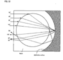
- the retroreflective efficiency of the enclosed lens type reflective sheet is calculated in FIG. 22.
- the retroreflective efficiency is defined as the ratio of reflected light rays which are considered to have returned within a shear (displacement) angle of 15° from the incident direction among the incident light rays.
- the refractive index of a resin layer is usually about 1.5, it is necessary to have a larger refractive index than that of the resin layer to cause a glass bead to act as the lens.
- the refractive index of a resin layer is usually about 1.5, it is necessary to have a larger refractive index than that of the resin layer to cause a glass bead to act as the lens.
- the refractive index of a resin layer is usually about 1.5, it is necessary to have a larger refractive index than that of the resin layer to cause a glass bead to act as the lens.
- a focus position of the glass bead of which the refractive index is 1.5 can conduct the retroreflection most efficiently by bringing the reflective surface to a position where it is 1.38 times as long as the hemisphere (R) of the bead.
- R hemisphere
- the enclosed lens type reflective sheet is provided to bring the reflective surface to a position where it is about 1.38 times as long as the bead's hemisphere (R).
- the focus position varies with the incident height angle of light (an angle relative to the center of the glass bead) as shown in FIG. 22. Namely, the focus position does not change so much when the incident height angle is between 0° and 30°, but the focus position moves forward when the incident height angle is more than 30°. As a result, the outgoing direction of the reflected light deviates greatly from the incident direction of the incident light and no retroreflection is conducted.
- non-uniformity of the glass bead in particle diameter affects the reflective efficiency.
- the particle diameter of the bead be constant and the beads which have been well sorted within the limits of 50-100 ⁇ m are used.
- the reflective efficiency is reduced by about 22 % due to the non-uniformity of the particle diameter compared with using the beads of which the particle diameters are the same and ideal.
- the reflective efficiency of the enclosed lens type reflective sheet is about 2.2 %, it is considered that the reflective efficiency of the capsule lens type reflective sheet is about 6.6 % and that of the prism lens type reflective sheet is about 20 %, judging from the value of the retroreflective brightness.
- the cube corner type reflective sheet has an excellent retroreflective efficiency in that the incident angle for retroreflection is extremely limited, but in a specific range, 20 % of the incident light retroreflects within the scope of ⁇ 1.5°.
- the cube corner type reflective sheet is used as a visual guide sign (a delineator) for a guard rail in a highway, all of the retroreflective light of ⁇ 1.5° does not enter the eyes of a driver, but only a part thereof.
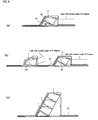
- FIG. 23 is a view showing the spread of light reflecting from a retroreflector toward a vehicle and FIG. 24 is a view explaining to what extent the retroreflective light enters the driver's eyes, wherein (a) is a plan view, (b) is a side view, and (c) is a view as seen from the arrow direction C of (b), respectively.
- the distance from the driver's eyes to the retroreflector is 40 m
- the vertical distance from the headlight to the position of the driver's eyes is 50 cm
- the distance between the driver's eyes is 6 cm (3 cm + 3 cm)
- the angle (an observation angle) between the driver's eyes and the reflector is 0.716°.
- the relationship between toric rays of light in the direction of the observation angle of 0.716° and the driver's eyes is such that 6cm of both eyes' width exists at the upper portion of the toric ring of 0.716° as shown in FIGS. 24 (a) and (b).
- the upper triangle of the upper and lower triangles becomes a section where the light directed toward the driver's eyes is reflected.
- the light rays with the observation angle of 0.716° among the light rays with the observation angles of 0° -15° reflected from this section finally become the effective light which enter the eyes of the driver who is 40 m away from the reflector.
- the extent of the ratio of the light rays reflected in the direction of the position of the driver's eyes among the retroreflected light rays is very important. Namely, it is considered that the retroreflective properties are proportional to the value obtained by multiplying the retroreflective efficiency by the ratio of light reflected in the direction of the driver's eyes.
- the distance between the driver's eyes and the reflector is set 40 m in FIG. 24, the same value can be obtained even though the distance is changed to 120 m. In such a sense, there is considerable room for improvement in the retroreflective properties of even the cube corner type reflective sheet which has the most excellent retroreflective properties in the present circumstances.
- a reflective material provided with more excellent retrortilective properties is required.
- a delyeror of which the diameter is 70 mm or more is generally used above a guardrail as a visual guide sign for a guardrail on a highway.
- the visual guide sign (delineator) on a depressed portion at the center of the guardrail.
- the retroreflective brightness becomes insufficient and only such a structure as shown in the Patent Document 5 can be made available.
- a retroreflective function member comprising a flat plate-shaped transparent body made of acrylic resin and the like, in which the front surface is an incident and outgoing surface, the rear surface is a reflective surface provided with aluminum deposition and the like, the upper and lower surfaces are flat surfaces, and at least one surface of both side surfaces is a flat reflective surface, wherein the front surface projects forward to have a cylindrical shape (i.e., the shape in which a column is axially cut) when seen from the side and at least one surface of the rear surface and both side surfaces is a bow shape or an inverse bow shape.
- a cylindrical shape i.e., the shape in which a column is axially cut
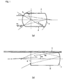
- FIG. 1 (a) is a side view of which the intermediate part is omitted
- the vertical retroreflection is conducted in such a manner that light incident on the front surface 6 of a lens body goes straight through the lens body after refraction, reflects on a reflective surface of the rear surface 7 of the lens body, and is emitted from the front surface 6 of the lens body as reflected light.
- the reflective surface is situated near a focal position of the incident light, for example, when the curvature radius of the front surface 6 is R1 viewed from the side, a curvature radius of the rear surface 7 is R2 viewed from the side, and R2 / R1 ⁇ 2.0, all the reflected light ratroreflecting in the incident direction.
- R2 / R1 the flux of retroreflected light in the vertical direction is narrowed or widened.
- the refractive index of a medium (i.e., a transparent body) on which the light is incident varies with the wavelength of the incident light (A normal refraction index has an intermediate value).
- the relationship between the radius R1 of curvature of the front surface 6 and the radius R2 of curvature of the rear surface 7 is 1.5 ⁇ R2 / R1 ⁇ 2.5, preferably 1.7 ⁇ R2 /, R1 ⁇ 2.0. If R2 / R1 (H1) is below 1.5, the extent (spread) of light flux of the reflected Light in the vertical direction becomes too large. If R2 / R1 is approximately 2.0, the light flux of the reflected light in the vertical direction is reduced to the fullest extent. On the contrary, if R2 / R1 is above 2.5, the extent of the light flux of the reflected light in the vertical direction becomes too large.
- the retroreflection in the horizontal direction is provided in such a manner that the light incident on the front surface 6 of the lens body goes straight through the lens body after refraction, reflects on the reflected surface of the rear surface 7 of the lens body, then reflects on the side surface 4, and is emitted from the front surface 6 of the lens body as reflected light.
- the dimension of R3 is large, the angle between the rear surface 7 and the side surface 4 of the lens body becomes substantially 90°, thus all the reflected light retroreflects in the incident direction.
- the value of R3 the light flux of the retroreflective light in the horizontal, direction is reduced or widened.
- the center of the curvature radius R3 of the rear surface when viewed from the top be situated between the central axis of the incident light and an extension of the reflective side surface.
- the thickness of the retroreflective function member when viewed from the side be provided in such a manner that an angle ( ⁇ 1) between the incident light from the horizontal direction and the line passing through the center of curvature radius of the front surface is within 30°.
- ⁇ 1 an angle between the incident light from the horizontal direction and the line passing through the center of curvature radius of the front surface is within 30°.
- an angle ( ⁇ 2) between a line connecting the end section of the rear surface of the retroreflective function member in the width direction viewed from the top with the center of the radius of curvature of the rear surface and an axis line passing through the center of the radius of curvature of the rear surface is 0.01° ⁇ ⁇ 2 ⁇ 1.0°, preferably 0.02° ⁇ ⁇ 2 ⁇ 0.5°.
- ⁇ 2 is smaller than 0.01°, the light flux in the horizontal direction is reduced too much and as a result, the reflected light does not return to the driver's view unless it is a very long distance of 400 m or more.
- a rotrareflective unit comprises a lens unit formed by laminating a plurality of retroreflective function members in the vertical direction with the front surface and the side surface aligned.
- the front surface becomes lenticular (a series of shapes formed by axially cutting a column).
- the efficiency of the unit itself improves because optimum conditions can be attained for any of the retroreflective function members.
- FIG. 2 is a perspective view of a retroreflective function member according to the present invention.
- FIG. 3 (a) is a side view of the retroreflective function member according to the present invention
- FIG. 3 (b) is a plan view of the retroreflective function member according to the present invention
- FIG 3 (c) is a plan view of another embodiment.
- a retroreflective function member 1 is formed by injection molding the transparent acrylic resin and is substantially plate-shaped, in which the upper surface 2, the lower surface 3, and right and left side surfaces 4 and 5 are formed flat.
- the front surface 6 is the incident (incoming) and outgoing surface
- the rear surface 7 is aluminum-deposited to serve as a reflected surface
- the outside of the rear surface 7 is protected by a resin 8.
- the side of the retroreflective function member 1 is not particularly limited, but the width is about 10 - 20 mm, the thickness is about 2.5 - 6 mm, and the length is about 15 - 30 mm.
- the front surface 6 projects forward to have a cylindrical shape when viewed from the side and the rear surface 7 projects backwards to have a convex aspheric surface (i.e., a bow shape) viewed from the top.
- a convex aspheric surface i.e., a bow shape
- the retroreflective function member 1 is used as a visual guide sign on a highway, it is intended to allow the reflected light from the retroreflective function member 1 to be viewed by a driver at a distance of 25 - 400 m in just proportion.
- the retroreflective function member is designed in such a manner that an angle between a line connecting an end section of the rear surface 7 in the width direction with the center of a curvature radius R3 of the rear surface when viewed from the top and an axis line passing through the center of the curvature radius R3 of the rear surface is 0.02° ⁇ ⁇ 2 ⁇ 0.5°.
- the reason for this is to limit the extent of light flux of the reflected light in the horizontal direction to a certain degree.
- the retroreflective function member 1 is used as the visual guide sign on a highway, it is intended to allow the reflected light from the retroreflective function member 1 to be viewed by the driver at a distance of 25 - 400 m in just proportion.
- the retroreflective function member 1 when the retroreflective function member 1 is designed in such a manner that 82 is 0.1°, the reflecting light is reduced to within ⁇ 0.3° in the horizontal direction around the light axis.
- the rear surface 7 projects backwards to have a bow shape when viewed from the top, but as shown in FIG. 3 (c), it may have an inverse bow shape which concaves forward. Even in this case, the rear surface 7 has a shape which projects backwards when viewed from the side.
- the thickness of the retroreflective function member when viewed from the side be provided in such a manner that the angle ( ⁇ 1: refer to FIG. 1) between the incident light from the horizontal direction and the line passing through the center of the curvature radius of the front surface is within 30°.
- ⁇ 1 refer to FIG. 1
- FIG. 4 is a perspective view showing another embodiment.
- a plurality of retroreflective function members 1 is laminated in the vertical direction with the front and side surfaces aligned to have a lens unit 11.
- Each retroreflective function member 1 forming the lens unit 11 may be the same, but retroreflective function members with different characteristics may also be laminated.
- the lens unit 11 of the shape formed by laminating retroreflective function members 1 may be integrally formed.
- FIG. 5 (a) is a plan view of a lens body according to another embodiment
- FIG. 5 (b) is a view as seen from the arrow direction b of (a)
- FIG 5 (c) is a view similar to (b) showing another embodiment.
- a shape of the front surface 6 is made linear when viewed from the top and projects forward to have a cylindrical shape when viewed from the side.
- the rear surface 7 is about half the width (15 mm) of the front surface 6 when viewed from the top and projects backwards to have a convex aspheric surface shape viewed from the top and side. In this manner, even by making the width of the rear surface 7 half the width of the front surface 6, it is possible to retroreflect all the incident light from the front surface 6. It is therefore useless to have extra width and convenient to make the visual guide sign (delineator) slim.
- the side surface 4 contributing to retroreflection is made flat, but the side surface 5 is provided partly with a notch 5a for easy positioning in the case where the lens body is incorporated in the casing as a unit or for easily locking other members.
- the center of the curvature radius (R1) of the front surface coincides, on the center line, with the center of the curvature radius (R2) of the rear surface 7 when viewed from the side.
- the center of the curvature radius (R1) of the front surface 6 at the rear of the center of the curvature radius (R2) of the rear surface 7, namely by overlapping them on the center line when viewed from the side, it is possible to widen the retroreflectable incident angle in the vertical direction.
- FIGS. 6 (a) - (c) show a plan view of a retroreflective unit in which the lens body of the above shape is incorporated.
- the lens body as shown in FIG. 5 is designed to most efficiently retroreflect the incident light at an angle of 35° relative to a perpendicular line of the front surface 6.
- the most efficient angle is determined by the refractive index of the lens body and the ratio of the width and the length thereof.
- the lens body 1 is installed at a slope of 35° relative to a casing 31 and designed to most efficiently reflect the incident light of 0° based on the longitudinal direction of the casing 31.
- FIG. 6 (a) Only one lens body 1 is shown in FIG. 6 (a), but a plurality of lens bodies 1 may be laminated in the vertical direction of the paper to provide a lens unit. Although a supporting plate 32 is pushed against the side surface 4 of the lens body 1 in the figure, the supporting plate 32 may be omitted.
- the lens bodies 1, 1 are separately mounted in the longitudinal direction on the casing 31. Since the front lens body 1 is mounted at a slope of 35° relative to the casing 31, it reflects the incident light of 0° most efficiently, but the rear lens body 1 is mounted at a slope of 15° relative to the casing 31. As a result, the rear lens body 1 reflects the incident light of 20° most efficiently.
- a retroreflective unit is suitably applied to a corner section of a road.
- a plurality of lens bodies 1 is laterally laminated and held within the casing 31.
- the absolute amount of retroreflective light increases.
- the installation angle of the lens bodies 1 relative to the casing 31 is set at 35°, but each lens body may be installed at a different angle. It is also possible to laminate the lens body in the vertical direction to the paper.
- FIG. 7 is a view similar to FIG. 5 showing another embodiment.
- the shape of the side surface 4 and the rear surface 7 differs from that of the previous embodiment.
- FIG. 8 is a substantially plan view of a metal mold for injection molding the lens body according to another embodiment as shown in FIG 5.
- the injection molding equipment comprises movable metal molds 21 and 22, a fixed metal mold 23, and upper and lower metal molds (not shown). By closing these metal molds, a cavity for molding is prepared in which molten resin is injected.
- the intersection point between the side surface 4 and the rear surface 7 is formed in advance within the metal mold 21, it is possible to obtain a lens body which excels in dimensional accuracy.
- the fixed metal mold 23 for forming the side surface 5 which does not contribute to the retroreflection is provided with a runner 24.
- FIG. 9 is a side view showing another embodiment of the retroreflective unit.
- FIG. 10 is a substantially plan view of the metal mold for injection molding the lens body according to another embodiment as shown in FIG. 9.
- a plurality of leas bodies 1 is vertically laminated, integrally formed in a given shape to have the lens unit 11, and housed within the casing 31.
- a transparent protective plate 32 is provided ahead of the lens unit 11.
- Injection molding equipment for molding the lens unit 11 comprises two metal molds 21 and 22. By bringing the parting line of these metal molds to an intersection point between the front surface 6 and the side surface 4 of the lens unit 11 and an intersection point between the rear surface 7 and the side surface 5, the parting line is removed from a location which affects the retroreflective function as described above.
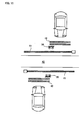
- FIG. 11 is a plan view of a road where the retroreflective unit according to the present invention is applied as the studs.
- the road crosses a railroad crossing and crossing bars 41 are provided in front of the crossing. Studs 50 are provided near limit lines 42 in front of the crossing bars 41 and at sections near the center of the road.
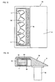
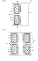
- FIG. 12 is a plan view showing the inner structure of the studs and FIG 13 is a cross-sectional view of the studs shown in FIG. 12.
- the studs 50 comprise a casing 51 made of aluminum die cast, a leg section 52 provided on the casing 51 and adapted to be embedded in the road, eaves 53 formed by extending pan of the casing 51, and a transparent lens box 55 secured to the lower surface of the eaves 53 via a shim.
- Housed within the lens box 55 is a plurality of lens units (6 pieces) via a fastening member 56.
- Each lens unit 11 is formed by laminating four lens bodies 1 and a front surface of adjacent lens units 11 is arranged to be alternated based on the axis line in the front and back direction. Specifically, an angle of +35° is formed between the front surface of three (3) lens units 11 among six (6) lens units 11 and the axis line in the front and back direction, while an angle of -35° is formed between the front surface of three (3) remaining lens units 11 and the axis line in the front and back direction.
- FIG. 14 is a plan view showing the inner structure of the studs according to another embodiment and FIG 15 is a cross-sectional view of the studs as shown in FIG. 14.
- This embodiment is for example provided on a center divider and the like, wherein the lens box 55 housing the lens units 11 is installed on both front and rear sides.
- FIGS. 16 and 17 are plan views showing the ixmer structure of the studs according to another embodiment.
- the lower center section of the eaves of the casing 51 is provided with a rib 57 to divide the lower space of the eaves into two sections, wherein a lens box 55 for housing the lens units 11 is installed in each space.
- FIG. 17 is an alteration of the embodiment as shown in FIG. 16, wherein the lens box 55 for housing the lens units 11 is installed in each space in both the front and rear sections.
- FIG. 18 is a longitudinal cross-sectional view of the studs according to another embodiment.
- the lens unit 11 is formed by laminating two (2) lens bodies 1.
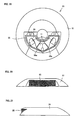
- FIG. 19 is a plan view showing the inner structure of the studs according to another embodiment.
- FIG. 20 is a front elevation view of the studs as shown in FIG. 19 and
- FIG. 21 is a side view of the studs as shown in FIG 19.
- a transparent lens box 55 housing the lens units 11 is installed in the casing 51 of a frustum of a cone shape made of aluminum die cast.
- the lens box 55 is formed substantially fan-shaped and a section of the front surface serving as the incident surface is made flat to reduce the influence of refractive index.
- the retroreflective function member (retroreflective unit)
- the visual guide sign (delineator)
- the present invention is not limited to the embodiments described above.
- the present invention can be widely applied to the members such as signs for marine salvage which are required to be visible from a long distance.
- a retroreflective function member according to the present invention can attain reflective performance (properties) of at a long distance more than 10 times (300 - 400 m) as high as a cube corner type retroreflective function member which is considered to be the most excellent in retroreflective efficiency among the conventional retroreflective function members.
- the retroreflective function member is installed in an extremely limited area such as a depressed section of a guardrail on the side surface, it is possible to fully exhibit the retroreflective function.
- studs using the retroreflective function member according to the present invention are highly visible from a long distance, and the retroreflective efficiency is high in comparison with studs in which conventional reflectors are incorporated. Since a driving source such as a solar battery is not required, this is also advantageous in cost.
Landscapes
- Physics & Mathematics (AREA)
- General Physics & Mathematics (AREA)
- Engineering & Computer Science (AREA)
- Optics & Photonics (AREA)
- Geometry (AREA)
- Theoretical Computer Science (AREA)
- Architecture (AREA)
- Civil Engineering (AREA)
- Structural Engineering (AREA)
- Road Signs Or Road Markings (AREA)
- Optical Elements Other Than Lenses (AREA)
Applications Claiming Priority (5)
| Application Number | Priority Date | Filing Date | Title |
|---|---|---|---|
| JP2002123463 | 2002-04-25 | ||
| JP2002367519 | 2002-12-19 | ||
| JP2002367519 | 2002-12-19 | ||
| JP2003123463 | 2003-04-28 | ||
| PCT/JP2003/016361 WO2004057379A1 (ja) | 2002-12-19 | 2003-12-19 | 再帰反射機能部材および再帰反射ユニット |
Publications (2)
| Publication Number | Publication Date |
|---|---|
| EP1580580A1 true EP1580580A1 (de) | 2005-09-28 |
| EP1580580A4 EP1580580A4 (de) | 2008-01-23 |
Family
ID=32684183
Family Applications (1)
| Application Number | Title | Priority Date | Filing Date |
|---|---|---|---|
| EP03780937A Withdrawn EP1580580A4 (de) | 2002-12-19 | 2003-12-19 | Rückstrahlendes funktionselement und rückstrahleinheit |
Country Status (7)
| Country | Link |
|---|---|
| US (1) | US20060165961A1 (de) |
| EP (1) | EP1580580A4 (de) |
| JP (1) | JP3712408B2 (de) |
| KR (1) | KR20050085849A (de) |
| AU (1) | AU2003289454A1 (de) |
| CA (1) | CA2510830A1 (de) |
| WO (1) | WO2004057379A1 (de) |
Cited By (2)
| Publication number | Priority date | Publication date | Assignee | Title |
|---|---|---|---|---|
| EP1914584A3 (de) * | 2006-10-19 | 2010-10-20 | Samsung Electronics Co., Ltd. | Rückstrahlender Lichtleiter, Beleuchtungsvorrichtung damit und Projektionsanzeige mit der Beleuchtungsvorrichtung |
| RU2434255C1 (ru) * | 2010-06-30 | 2011-11-20 | Федеральное государственное унитарное предприятие Научно-исследовательский институт комплексных испытаний оптико-электронных приборов и систем (ФГУП НИИКИ ОЭП) | Световозвращающий элемент |
Families Citing this family (12)
| Publication number | Priority date | Publication date | Assignee | Title |
|---|---|---|---|---|
| WO2005124402A1 (ja) * | 2004-06-18 | 2005-12-29 | Osamu Tsutsui | 再帰反射機能部材およびロードマーカ |
| US8840956B2 (en) * | 2008-10-31 | 2014-09-23 | Potters Industries, Llc | Retroreflective coating and method for applying a retroreflective coating on a structure |
| JP5393140B2 (ja) * | 2008-12-26 | 2014-01-22 | 株式会社アイケー | 道路鋲 |
| US20100272962A1 (en) * | 2009-04-22 | 2010-10-28 | Potters Industries Inc. | Reflective substrate surface system, reflective assembly, and methods of improving the visibility of a substrate surface |
| US8647013B2 (en) * | 2010-02-09 | 2014-02-11 | Potters Industries, Llc | Reflective substrate surface system, reflective assembly, and methods of improving the visibility of a substrate surface |
| CN105894984A (zh) * | 2014-10-31 | 2016-08-24 | 王盘龙 | 标志、标牌广角度可视装置与方法和系统 |
| CN105445196A (zh) * | 2014-12-17 | 2016-03-30 | 邓文平 | 样品测量池 |
| JP7032053B2 (ja) * | 2017-04-13 | 2022-03-08 | 浜松ホトニクス株式会社 | 画像取得装置及び画像取得方法 |
| US10480138B2 (en) | 2017-06-05 | 2019-11-19 | David E. Lambert | Illuminated road marker |
| US10968583B2 (en) | 2017-07-26 | 2021-04-06 | David E. Lambert | Reflective road marker |
| US12113278B2 (en) * | 2019-05-24 | 2024-10-08 | 3M Innovative Properties Company | Radar retroreflective article |
| US11519143B1 (en) * | 2020-01-23 | 2022-12-06 | Harry E. Lowe | Reversible reflective pavement marker |
Family Cites Families (12)
| Publication number | Priority date | Publication date | Assignee | Title |
|---|---|---|---|---|
| BE345984A (de) * | ||||
| DE666028C (de) * | 1933-04-06 | 1938-10-10 | Italo Ferruccio Cerri | Rueckstrahler |
| US2067701A (en) * | 1933-06-27 | 1937-01-12 | A M Ducey | Reflecting glass |
| US2374003A (en) * | 1942-02-23 | 1945-04-17 | Arthur F Eckel | Collinear reflector |
| JPS343443Y1 (de) * | 1956-09-01 | 1959-03-10 | ||
| GB1508424A (en) * | 1975-06-30 | 1978-04-26 | Ass Eng Ltd | Reflectors |
| DE2936012A1 (de) * | 1979-09-06 | 1981-03-19 | Johann-F. Dipl.-Phys. 2000 Hamburg Hipp | Retroreflektoren mit doppelter retroreflexion |
| JPS6181601U (de) * | 1984-11-02 | 1986-05-30 | ||
| US4930870A (en) * | 1987-07-27 | 1990-06-05 | Itw New Zealand Limited | Retro-reflectors |
| JPH02235001A (ja) * | 1989-03-09 | 1990-09-18 | Rainfuaruto Kogyo Kk | 埋設型再帰反射性道路鋲 |
| JPH08220315A (ja) * | 1995-02-08 | 1996-08-30 | Nippon Hatsumei Fukiyuu Shinkoukai:Kk | 可変色反射素子 |
| WO1998018028A1 (fr) * | 1996-10-18 | 1998-04-30 | Nippon Carbide Kogyo Kabushiki Kaisha | Feuille retroreflechissante du type a angles cubiques tetraedriques |
-
2003
- 2003-12-19 JP JP2005502620A patent/JP3712408B2/ja not_active Expired - Fee Related
- 2003-12-19 AU AU2003289454A patent/AU2003289454A1/en not_active Abandoned
- 2003-12-19 US US10/539,533 patent/US20060165961A1/en not_active Abandoned
- 2003-12-19 KR KR1020057011623A patent/KR20050085849A/ko not_active Withdrawn
- 2003-12-19 CA CA002510830A patent/CA2510830A1/en not_active Abandoned
- 2003-12-19 EP EP03780937A patent/EP1580580A4/de not_active Withdrawn
- 2003-12-19 WO PCT/JP2003/016361 patent/WO2004057379A1/ja not_active Ceased
Cited By (2)
| Publication number | Priority date | Publication date | Assignee | Title |
|---|---|---|---|---|
| EP1914584A3 (de) * | 2006-10-19 | 2010-10-20 | Samsung Electronics Co., Ltd. | Rückstrahlender Lichtleiter, Beleuchtungsvorrichtung damit und Projektionsanzeige mit der Beleuchtungsvorrichtung |
| RU2434255C1 (ru) * | 2010-06-30 | 2011-11-20 | Федеральное государственное унитарное предприятие Научно-исследовательский институт комплексных испытаний оптико-электронных приборов и систем (ФГУП НИИКИ ОЭП) | Световозвращающий элемент |
Also Published As
| Publication number | Publication date |
|---|---|
| CA2510830A1 (en) | 2004-07-08 |
| EP1580580A4 (de) | 2008-01-23 |
| JP3712408B2 (ja) | 2005-11-02 |
| AU2003289454A1 (en) | 2004-07-14 |
| JPWO2004057379A1 (ja) | 2006-04-20 |
| WO2004057379A1 (ja) | 2004-07-08 |
| KR20050085849A (ko) | 2005-08-29 |
| US20060165961A1 (en) | 2006-07-27 |
Similar Documents
| Publication | Publication Date | Title |
|---|---|---|
| JP3931256B2 (ja) | 1つ以上の面において改善された照射角を形成するキューブコーナ製品 | |
| KR100901679B1 (ko) | 재귀반사장치 | |
| EP1580580A1 (de) | Rückstrahlendes funktionselement und rückstrahleinheit | |
| CA2293657C (en) | Dual axis retroreflective articles | |
| JP4777900B2 (ja) | 複合三角錐型キューブコーナー再帰反射シートおよび再帰反射物体 | |
| US6817724B2 (en) | Triangular pyramidal cube corner retroreflection element | |
| JP3824471B2 (ja) | キューブコーナー型再帰反射シート及びキューブコーナー金型 | |
| WO2005066665A1 (en) | Cube corner retroreflector with limited range | |
| JP2009537023A (ja) | 再帰反射体 | |
| JP4442731B1 (ja) | 標示具 | |
| WO1996011303A1 (en) | Reflective sheet | |
| JP5393140B2 (ja) | 道路鋲 | |
| JPH08201608A (ja) | 内部全反射型再帰反射シート | |
| KR20060085591A (ko) | 재귀반사유닛 및 그 재귀반사유닛을 구비한 재귀반사체 | |
| KR200421310Y1 (ko) | 재귀반사유닛 및 그 재귀반사유닛을 구비한 재귀반사체 | |
| JPH08211212A (ja) | 反射シートおよび反射効果板 | |
| KR100909386B1 (ko) | 교통안전표지용 재귀반사체 | |
| KR100924438B1 (ko) | 교통안전표지용 재귀반사체 | |
| CN1745318A (zh) | 回归反射功能部件及回归反射单元 | |
| MXPA97009540A (en) | Retrorreflector article of cubic corners that holds scalene triangles b | |
| MXPA97010349A (en) | Vertical retrorreflejante deliner of amp scale | |
| CA2536958A1 (en) | Method for improving the conspicuity of an object using dual axis reflective articles | |
| JPWO2001057560A1 (ja) | 三角錐型キューブコーナー再帰反射素子 |
Legal Events
| Date | Code | Title | Description |
|---|---|---|---|
| PUAI | Public reference made under article 153(3) epc to a published international application that has entered the european phase |
Free format text: ORIGINAL CODE: 0009012 |
|
| 17P | Request for examination filed |
Effective date: 20050715 |
|
| AK | Designated contracting states |
Kind code of ref document: A1 Designated state(s): AT BE BG CH CY CZ DE DK EE ES FI FR GB GR HU IE IT LI LU MC NL PT RO SE SI SK TR |
|
| AX | Request for extension of the european patent |
Extension state: AL LT LV MK |
|
| D17P | Request for examination filed (deleted) | ||
| R17P | Request for examination filed (corrected) |
Effective date: 20050715 |
|
| DAX | Request for extension of the european patent (deleted) | ||
| A4 | Supplementary search report drawn up and despatched |
Effective date: 20071227 |
|
| STAA | Information on the status of an ep patent application or granted ep patent |
Free format text: STATUS: THE APPLICATION HAS BEEN WITHDRAWN |
|
| 18W | Application withdrawn |
Effective date: 20080310 |