EP1580691A2 - Automatische Anpassung der Aufnahme eines Inspektionsbildes - Google Patents
Automatische Anpassung der Aufnahme eines Inspektionsbildes Download PDFInfo
- Publication number
- EP1580691A2 EP1580691A2 EP05251526A EP05251526A EP1580691A2 EP 1580691 A2 EP1580691 A2 EP 1580691A2 EP 05251526 A EP05251526 A EP 05251526A EP 05251526 A EP05251526 A EP 05251526A EP 1580691 A2 EP1580691 A2 EP 1580691A2
- Authority
- EP
- European Patent Office
- Prior art keywords
- image
- parameter
- image data
- processor
- modification information
- Prior art date
- Legal status (The legal status is an assumption and is not a legal conclusion. Google has not performed a legal analysis and makes no representation as to the accuracy of the status listed.)
- Withdrawn
Links
Images


Classifications
-
- G—PHYSICS
- G06—COMPUTING OR CALCULATING; COUNTING
- G06T—IMAGE DATA PROCESSING OR GENERATION, IN GENERAL
- G06T7/00—Image analysis
- G06T7/0002—Inspection of images, e.g. flaw detection
- G06T7/0004—Industrial image inspection
-
- G—PHYSICS
- G05—CONTROLLING; REGULATING
- G05B—CONTROL OR REGULATING SYSTEMS IN GENERAL; FUNCTIONAL ELEMENTS OF SUCH SYSTEMS; MONITORING OR TESTING ARRANGEMENTS FOR SUCH SYSTEMS OR ELEMENTS
- G05B13/00—Adaptive control systems, i.e. systems automatically adjusting themselves to have a performance which is optimum according to some preassigned criterion
-
- G—PHYSICS
- G05—CONTROLLING; REGULATING
- G05B—CONTROL OR REGULATING SYSTEMS IN GENERAL; FUNCTIONAL ELEMENTS OF SUCH SYSTEMS; MONITORING OR TESTING ARRANGEMENTS FOR SUCH SYSTEMS OR ELEMENTS
- G05B6/00—Internal feedback arrangements for obtaining particular characteristics, e.g. proportional, integral or differential
-
- G—PHYSICS
- G06—COMPUTING OR CALCULATING; COUNTING
- G06T—IMAGE DATA PROCESSING OR GENERATION, IN GENERAL
- G06T2207/00—Indexing scheme for image analysis or image enhancement
- G06T2207/30—Subject of image; Context of image processing
- G06T2207/30108—Industrial image inspection
- G06T2207/30141—Printed circuit board [PCB]
-
- G—PHYSICS
- G06—COMPUTING OR CALCULATING; COUNTING
- G06T—IMAGE DATA PROCESSING OR GENERATION, IN GENERAL
- G06T2207/00—Indexing scheme for image analysis or image enhancement
- G06T2207/30—Subject of image; Context of image processing
- G06T2207/30108—Industrial image inspection
- G06T2207/30152—Solder
Definitions
- the present invention relates generally to the field of image acquisition inspection systems and methods, in the preferred embodiments to adjustable image acquisition inspection systems using feedback mechanisms.
- Inspection systems are used in many different types of industries for a wide variety of purposes.
- automated inspection systems are commonly employed in the manufacturing industry to inspect objects, such as solder joints and other components, on printed circuit boards (PCBs) for quality control purposes.
- the output is a classification of an inspected object into one of a few categories.
- a component can be categorized as present or absent, while a solder-joint can be categorized as good or bad.
- the final classification of the object is made after an image of the object is acquired and processed.
- the flow of information in inspection systems is one way, from the image acquisition system to the image processing system to the classifier.
- the performance of the overall inspection system is measured by the output of the classifier.
- the performance of the classifier is directly affected by the performance of the image acquisition system and the image processing system. Therefore, to improve the performance of the overall system, adjustments are typically made to the image acquisition and image processing systems. For example, adjustments can be made to compensate for variations in the illumination intensity between inspection systems, variations in the PCB design and layout, thickness variations between different PCBs, material changes between different objects and customer-specific requirements.
- an inspection system capable of automatically making adjustments to the image acquisition and image processing systems based on information from the later stages of the inspection, such as the classification stage.
- the present invention seeks to provide improved image acquisition.
- Embodiments of the present invention provide an inspection system and method for providing feedback during an inspection of an object.
- the inspection system includes a device to capture an image and a processor that receives image data representing the object.
- the processor is operable to determine parameter modification information from the image data and modify an image parameter used during the production of the image data with the parameter modification information.
- the modified image parameter is used during the production of subsequent image data representing the object.
- the image parameter is an image acquisition parameter.
- image acquisition parameters include illumination parameters, such as the intensity of illumination, angle of illumination or duration of illumination, image view parameters, such as the positional relationship between the object and a sensor operable to capture an image of the object, and sensor parameters, such as the exposure duration of the sensor or resolution of the sensor.
- the processor is an image processor operable to process the image data and calculate the parameter modification information for the image acquisition parameter based on the processed image data.
- the processor is a classification processor operable to output a classification and calculate the parameter modification information for the image acquisition parameter based on the classification. For example, if the classification is incorrect as a result of an original setting of the image acquisition parameter, the classification processor is operable to calculate the parameter modification information to correct the incorrect classification and modify the original setting of the image acquisition parameter to a modified setting based on the parameter modification information.
- the image parameter is an image processing parameter.
- image processing parameters include processing type parameters, such as the type of algorithm used to process the image data, and processing complexity parameters, such as the complexity of the algorithm used to process the image data.
- the processor is a classification processor operable to output a classification and calculate the parameter modification information for the image processing parameter.
- FIG. 1 is a simplified illustration of an inspection system 100 capable of providing internal feedback to automatically make adjustments in real time.
- the inspection system 100 can be, for example, an automated printed circuit board inspection system, other manufacturing inspection system, luggage inspection system used in airport security or other type of inspection system.
- the inspection system 100 includes an image acquisition system 120 having an illumination source 110 for illuminating an object 130 and a sensor 140 including a plurality of pixels for capturing an image of the object 130 and producing raw image data 145 representing the image of the object 130.
- the illumination source 110 is an X-ray source that produces a beam of X-rays and projects the X-ray beam through the object 130 to the sensor 140.
- the illumination source 110 is a light source that emits light towards the object 130.
- the light is reflected off the surface of the object 130 and received by the sensor 140.
- other illumination sources 110 or combinations of illumination sources 110 can be used to illuminate the object 130, and various types of sensors 140 can be used to capture the image(s) of the object 130.
- the inspection system 100 further includes a processor 150 for receiving the raw image data 145 representing the image of the object 130.
- the processor 150 can be a microprocessor, microcontroller, programmable logic device or other type of processing device capable of performing the functions described herein.
- the processor 150 can include multiple processors or be a single processor having one or more processing elements (referred to herein as separate processors).
- the processor 150 includes an image processor 160 and a classification processor 170.
- the image processor 160 is connected to receive as input the raw image data 145 from the sensor 140, and operates to process the raw image data 145 and output processed image data 165.
- the image processor 160 can demosaic the image.
- Demosaicing is a process by which missing color values for each pixel location are interpolated from neighboring pixels.
- demosaicing methods There are a number of demosaicing methods known in the art today. By way of example, but not limitation, various demosaicing methods include pixel replication, bilinear interpolation and median interpolation.
- image processor 160 can perform other types of processing that the image processor 160 can perform.
- features of the object includes measurements of the object 130, components on a surface of or within the object 130 or other indicia of the object 130.
- An example of an image reconstruction process for three-dimensional images is described in co-pending and commonly assigned International patent application no. WO 2004/086015.
- the classification processor 170 is connected to receive as input the processed image data 165 from the image processor 160, and operates to classify one or more features of the object 130 from the processed image data 165 and output a classification 175 of the object feature(s). For example, if an extracted feature is a solder joint on a printed circuit board, the classification processor 170 can analyze the processed image data 165 and output a classification 175 indicating whether the solder joint is good or bad. As another example, if an extracted feature is another component on a printed circuit board, the classification processor 170 can analyze the processed image data 165 and output a classification 175 indicating whether the component is present or absent.
- classifications 175 that can be output by the classification processor 170 include measurements of specific aspects of one or more features of the object 130, such as the size of a solder joint or another component, volume of a solder joint or another component, location or position of a component or size of the object 130.
- the classification 175 is also stored in a computer-readable medium 180 for later processing or display.
- the computer-readable medium 180 can be a memory device, such as random access memory (RAM), read-only memory (ROM), flash memory, EEPROM, disk drive, compact disk, floppy disk or tape drive, or any other type of storage device.
- Additional processing information can also be stored on the computer-readable medium 180 and accessed by the image processor 160 and classification processor 170.
- processing information can include various processing parameters, such as algorithms that can be used to process the raw or processed image data 145 or 165, respectively, and varying complexities of the algorithms used to process the raw or processed image data 145 or 165, respectively.
- processing information can include feature specifications or other metrics against which the processed image data 165 can be measured to determine the classification 175.
- the flow of data is in one direction, from the image acquisition system 120 to the image processor 160 to the classification processor 170.
- the performance of the inspection system is measured by the output of the classification processor 170, and any adjustments that need to be made to the image acquisition system 120 or image processor 160 are conventionally made manually, off-line.
- the manual adjustment process is labor-intensive, time consuming and error-prone.
- adjustments are made automatically with improved reliability and increased speed by altering the flow of data to provide feedback between the various parts of the inspection system 100.
- feedback from the image processor 160 and classification processor 170 are provided to the image acquisition system 120 to modify one or more parameters of the image acquisition system 120, such as the settings of the illumination source or the sensor.
- feedback from the classification processor 170 is provided to the image processor 160 to modify one or more parameters of the image processor 160, such as the type of algorithm or complexity of algorithm used to process the raw image data.
- feedback is provided only in a "tuning" mode of the inspection system 100 instead of during the run-time to prevent any impact to the in-line running time.
- feedback is provided in real time during the operation of the inspection system 100, to compensate for drift in various parameters.
- feedback is provided during a "learning" mode for a batch of objects, such as printed circuit boards. For example, while in a "leaming" mode, the inspection system 100 acquires multiple images of the object, each image being taken using a different illumination setting and/or view.
- the image processor 160 and classification processor 170 determine the optimal images and algorithms that are needed to produce an optimal classification of the object.
- the inspection system 100 acquires the optimal images and uses the optimal algorithms when running at full production speed.
- FIG. 3 is a flow chart illustrating an exemplary process 300 for providing feedback within an inspection system, in accordance with embodiments of the present invention.
- the feedback process begins at block 310.
- first image data representing the object is received.
- the first image data is produced using at least one image parameter.
- the first image data can be raw image data representing an image of an object or processed image data.
- the image parameter can be an image acquisition parameter related to the illumination, a view or sensor setting used when the image was acquired or an image processing parameter related to the algorithm(s) used in processing the image data.
- parameter modification information is determined at block 330.
- the parameter modification information is used to modify the image parameter at block 340 to improve the performance of the inspection system.
- parameter modification information is calculated to modify the specific image parameter to produce image data within the tolerance for that specific image parameter. For example, if the average reflected illumination intensity over the image or over a portion of the image is below a predetermined threshold, the illumination intensity of the illumination source is increased by an amount sufficient to produce image data having an average reflected illumination intensity above the threshold. Other examples are discussed below in connection with FIG. 4.
- parameter modification information is calculated to modify one or more of the image parameters used to capture the first image data to correct the classification of the object or to enable the inspection system to classify the object. For example, if it is determined that the incorrect classification is due to the type of algorithm used to process the image data, the parameter modification information identifies a different algorithm to be used to process the image data and produce a correct classification. The cause of the incorrect classification is determined by the operator or automatically by the system using a diagnostic algorithm that analyzes the image data and compares the image data to predetermined criteria (e.g., thresholds) for each of the image parameters.
- predetermined criteria e.g., thresholds
- second image data representing the object is received.
- the second image data is produced using the modified image parameter.
- the feedback process ends at block 360. It should be understood that in other embodiments, the feedback process can continually provide feedback to make adjustments to one or more of the image parameters, as needed.
- FIG. 4 is a simplified representation of an inspection system 100 providing feedback from the image processor 160 to the image acquisition system 120 of the inspection system 100 to modify an image acquisition parameter 400 of the image acquisition system 120, in accordance with one embodiment of the present invention.
- the image acquisition parameter 400 controls one or more elements of the image acquisition system 120.
- image acquisition parameters 400 include, but are not limited to, illumination parameters, such as the intensity of illumination, angle of illumination or duration of illumination, image view parameters, such as the positional relationship between the object and the sensor, and sensor parameters, such as the exposure duration of the sensor or resolution of the sensor.
- the image acquisition system 120 captures an image of the object and provides raw image data 145 representing the image of the object to the image processor 160.
- the image processor 160 processes the raw image data 145 and determines parameter modification information 450 based on the raw and/or processed image data.
- the parameter modification information 450 is fed back to the image acquisition system 120 to modify the image acquisition parameter 400 for capturing a subsequent image of the object.
- Examples of parameter modification information 450 include, but are not limited to, a modification to the power of the X-ray, a modification to the particular areas on the object to focus on, a modification to the integration time of the X-ray, a modification to the view of the object and a modification to the illumination.
- the image processor 160 can detect that the image is too dark, too bright or has insufficient dynamic range from the raw image data 145 and can provide parameter modification information 450 to the image acquisition system 120 to adjust the illumination power and duration, and the mode of operation of the sensor.
- the image processor 160 can detect that the image has excessive resolution or dynamic range in certain portions of the image, and can provide parameter modification information 450 to the image acquisition system 120 to lower the resolution or dynamic range. In this case, by reducing the acquired resolution or dynamic range, the speed of the image acquisition system 120 is increased.
- the image processor 160 can determine from the raw and/or processed image data that wider-angle images are needed for reliable X-ray reconstruction.
- the parameter modification information 450 is fed back to the image acquisition system 120 to acquire more images using a different Z-height.
- the image processor 160 can detect that information is missing in certain areas, due to shadowing or steep angles.
- the parameter modification information 450 is fed back to the image acquisition system 120 to change the angle of illumination or types of lighting rings used to illuminate the object.
- FIG. 5 is a flow chart illustrating an exemplary process 500 for providing feedback within an inspection system to modify an image acquisition parameter based on raw and/or processed image data.
- the feedback process begins at block 510.
- an image acquisition parameter is set to capture a first image of the object.
- parameter modification information is determined at block 530.
- the parameter modification information is used to modify the image acquisition parameter at block 540 to capture a second image of the object.
- the feedback process ends at block 550. It should be understood that in other embodiments, the feedback process can continually provide feedback to make adjustments to one or more of the image acquisition parameters, as needed.
- FIG. 6 is a simplified representation of an inspection system 100 providing feedback from the classification processor 170 to the image processor 160 or image acquisition system 120 of the inspection system 100 to modify an image processing parameter 600 or an image acquisition parameter 400, in accordance with another embodiment of the present invention.
- the image acquisition parameter 400 controls one or more elements of the image acquisition system 120.
- the image processing parameter 600 controls one or more aspects of the image processor 160. Examples of the image processing parameter 600 include a processing type parameter, such as the type of algorithm used to process the image data, and a processing complexity parameter, such as the complexity of the algorithm used to process the image data.
- the image acquisition system 120 captures an image of the object and provides raw image data 145 representing the image of the object to the image processor 160.
- the image processor 160 processes the raw image data 145 using an original setting of the image processing parameter 600 and outputs processed image data 165 to the classification processor 170.
- the classification processor 170 classifies the object and determines parameter modification information 450 based on the classification of the object and/or processed image data 165.
- the parameter modification information 450 is fed back to either or both of the image acquisition system 120 to modify the image acquisition parameter 400 for capturing a subsequent image of the object and the image processor 160 to modify the image processing parameter 600 for processing the raw image data 145 representing the current image and/or the raw image data 145 representing a subsequent image of the object.
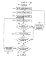
- FIG. 7 is a flow chart illustrating an exemplary process 700 for providing feedback within an inspection system to modify an image acquisition parameter based on a classification.
- the feedback process begins at block 710.
- an image acquisition parameter is set to capture an image of the object and produce raw image data representing the image of the object at block 730.
- the raw image data is processed to produce processed image data at block 740, and at block 750, one or more features of the object are classified based on the processed image data.
- a determination is made whether one or more of the image acquisition parameters should be modified due to an incorrect classification of one or more of the features.
- parameter modification information is determined, and at block 780, the parameter modification information is used to modify the image acquisition parameter.
- the modified image acquisition parameter is used to produce subsequent raw image data representing a subsequent image of the object at block 730. If no modification to the image acquisition parameter is necessary, the feedback process ends at block 790. It should be understood that in other embodiments, the feedback process can continually provide feedback to make adjustments to one or more of the image acquisition parameters, as needed.
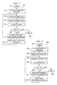
- FIG. 8 is a flow chart illustrating an exemplary process 800 for providing feedback within an inspection system to modify an image processing parameter based on a classification.
- the feedback process begins at block 810.
- an image processing parameter is set.
- raw image data representing an image of the object is received, and at block 840, the raw image data is processed to produce processed image data.
- one or more features of the object are classified based on the processed image data.
- a determination is made whether one or more of the image processing parameters should be modified due to an incorrect classification of one or more of the features.
- parameter modification information is determined, and at block 880, the parameter modification information is used to modify the image processing parameter.
- the modified image processing parameter is used to process the raw image data representing the current image of the object and/or a subsequent image of the object at block 840. If no modification to the image processing parameter is necessary, the feedback process ends at block 890. It should be understood that in other embodiments, the feedback process can continually provide feedback to make adjustments to one or more of the image processing parameters, as needed.
- FIG. 9 is a flow chart illustrating an exemplary process 900 for providing feedback within a closed-loop inspection system to modify the image acquisition parameter and/or image processing parameter.
- the feedback process begins at block 905.
- all image parameters including image acquisition parameters and image processing parameters, are set.
- an image of the object is captured, and at block 920, raw image data representing the image of the object is produced.
- the raw image data is processed to produce processed image data at block 925.
- a determination is made whether one or more of the image acquisition parameters should be modified based on the processed and/or raw image data. If modification is necessary, at block 935, parameter modification information is determined and the parameter modification information is used to modify the image acquisition parameter.
- the modified image acquisition parameter is used to capture a subsequent image of the object at block 915.
- modification of an image acquisition parameter is not necessary, at block 940, one or more features of the object are classified based on the processed image data.
- parameter modification information is determined and the parameter modification information is used to modify the image processing parameter.
- the modified image processing parameter is used to process the raw image data representing the current image of the object and/or a subsequent image of the object at block 925. If no modification to the image processing parameter is necessary, the feedback process ends at block 960. It should be understood that in other embodiments, the feedback process can continually provide feedback to make adjustments to one or more of the image parameters, as needed.
- FIG. 10 is a pictorial representation of an exemplary inspection system 100.
- the inspection system 100 includes an apparatus 1050 that images an object 130 (e.g., a printed circuit board) to inspect features 1000 (e.g., solder joints and other components) of the object 130.
- the apparatus 1050 includes at least a portion of the image acquisition system 120 of FIG. 1.
- the apparatus 1050 includes the illumination source 110 and sensor 140 of FIG. 1.
- the object 130 is transferred into the apparatus 1050 by a conveyer belt 1010.
- Image data representing an image of the object 130 is transmitted to a computer 1040 that embodies image processor 160 and classification processor 170 (both shown in FIG. 1) for processing the image data and classifying the features 1000 of the object 130.
- the computer 1040 provides parameter modification information generated by the image processor 160 and/or classification processor 170 to the apparatus 1050 to modify one or more image acquisition parameters.
- the classification processor 170 provides image acquisition parameters to the image processor 160 to modify one or more image processing parameters.
- a user interface 1030 e.g., keyboard, mouse, touch screen, light pen or other interface
- the user interface 1030 enables the operator to cause the classification processor to provide parameter modification information to the image processor and/or image acquisition system when the operator determines the displayed classification is incorrect.
- FIG. 11 is a pictorial representation of a simplified, exemplary X-ray automated inspection system 1150.
- the X-ray automated inspection system 1150 shown in FIG. 11 forms at least a portion of an embodiment of the image acquisition system 120 of FIG. 1.
- the X-ray automated inspection system 1150 includes a power supply 1100 for producing and impressing a high voltage upon an X-ray tube 1110, which in turn, generates X-rays.
- the X-rays are emitted in a fan beam 1120 that projects down through an object 130 or portion of an object 130 passing through the beam 1120 on a conveyer belt 1010.
- the beam 1120 passes through a portion of the object 130 containing a feature 1000 of interest.
- the beam 1120 impinges upon a sensor 140 to produce an image based on the cross-sectional density of the object 130, including feature 1000.
- the sensor 140 includes a row of detector elements forming a linear array. Typically, there are between 300 and 700 individual detector elements arranged in a linear array.
- the linear array is sequentially scanned as the object 130 is moved over the sensor by the conveyor belt 1010, and the image generated is a two-dimensional "gray scale" raster image.
- Raw image data representing the raster image is sent to a processor (not shown) in accordance with the present invention for analysis and classification of the feature and/or object, as described above in connection with FIG. 10.
- the processor can provide parameter modification information to either or both of the power supply 1100 and the sensor 140 to modify one or more image acquisition parameters.
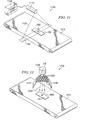
- FIG. 12 is a pictorial representation of an optical automated inspection system 1250.
- the optical inspection system 1250 shown in FIG. 12 forms at least a portion of an embodiment of the image acquisition system 120 of FIG. 1.
- the optical automated inspection system 1250 includes a light ring 1210 containing circular arrays 1240 of light-emitting elements 1220 (e.g., light-emitting diodes) arranged concentrically about the optical axis of an aperture of a camera 1200.
- Light 1230 emitted from the light-emitting elements 1220 illuminates the surface of an object 130 placed under the light ring 1210 by the conveyer belt 1010. Light reflected off the surface of the object 130 is received by an image sensor 140 in the camera 1200.
- the image sensor 140 captures an image of the object 130 or of one or more features 1000 on the surface of the object 130.
- the image sensor 140 can be a CCD or CMOS image sensor capable of producing raw image data representing the image.
- the raw image data is sent to a processor (not shown) in accordance with this embodiment for analysis and classification of the feature and/or object, as described above in connection with FIG. 10.
- the processor can provide parameter modification information to either or both of the light ring 1210 and the sensor 140 to modify one or more image acquisition parameters.
Landscapes
- Engineering & Computer Science (AREA)
- Physics & Mathematics (AREA)
- General Physics & Mathematics (AREA)
- Computer Vision & Pattern Recognition (AREA)
- Quality & Reliability (AREA)
- Theoretical Computer Science (AREA)
- Automation & Control Theory (AREA)
- Evolutionary Computation (AREA)
- Artificial Intelligence (AREA)
- Medical Informatics (AREA)
- Software Systems (AREA)
- Health & Medical Sciences (AREA)
- Image Analysis (AREA)
- Image Processing (AREA)
- Analysing Materials By The Use Of Radiation (AREA)
- Investigating Materials By The Use Of Optical Means Adapted For Particular Applications (AREA)
- Image Input (AREA)
Applications Claiming Priority (2)
| Application Number | Priority Date | Filing Date | Title |
|---|---|---|---|
| US10/805,748 US20050207655A1 (en) | 2004-03-22 | 2004-03-22 | Inspection system and method for providing feedback |
| US805748 | 2004-03-22 |
Publications (2)
| Publication Number | Publication Date |
|---|---|
| EP1580691A2 true EP1580691A2 (de) | 2005-09-28 |
| EP1580691A3 EP1580691A3 (de) | 2007-05-30 |
Family
ID=34862020
Family Applications (1)
| Application Number | Title | Priority Date | Filing Date |
|---|---|---|---|
| EP05251526A Withdrawn EP1580691A3 (de) | 2004-03-22 | 2005-03-14 | Automatische Anpassung der Aufnahme eines Inspektionsbildes |
Country Status (5)
| Country | Link |
|---|---|
| US (1) | US20050207655A1 (de) |
| EP (1) | EP1580691A3 (de) |
| JP (1) | JP2005283577A (de) |
| KR (1) | KR20060044521A (de) |
| TW (1) | TW200532162A (de) |
Cited By (3)
| Publication number | Priority date | Publication date | Assignee | Title |
|---|---|---|---|---|
| EP1653408B1 (de) * | 2004-10-29 | 2008-08-13 | Mitutoyo Corporation | Verfahren zur automatischen Wiederbereitstellung von Bildverarbeitungsbausteinen |
| US9618329B2 (en) | 2008-05-19 | 2017-04-11 | Renishaw Plc | Optical inspection probe |
| DE102020213164A1 (de) | 2020-10-19 | 2022-04-21 | Robert Bosch Gesellschaft mit beschränkter Haftung | Regelungsverfahren zur Regelung eines Herstellungsverfahrens |
Families Citing this family (25)
| Publication number | Priority date | Publication date | Assignee | Title |
|---|---|---|---|---|
| AU2003902319A0 (en) | 2003-05-14 | 2003-05-29 | Garrett Thermal Systems Limited | Laser video detector |
| IL162921A0 (en) * | 2004-07-08 | 2005-11-20 | Hi Tech Solutions Ltd | Character recognition system and method |
| CA2883638C (en) * | 2004-11-12 | 2017-06-20 | Xtralis Technologies Ltd | Particle detector, system and method |
| US7991242B2 (en) | 2005-05-11 | 2011-08-02 | Optosecurity Inc. | Apparatus, method and system for screening receptacles and persons, having image distortion correction functionality |
| EP1886257A1 (de) | 2005-05-11 | 2008-02-13 | Optosecurity Inc. | Verfahren und system zum prüfen von gepäckstücken, frachtcontainern oder personen |
| GB0520829D0 (en) * | 2005-10-13 | 2005-11-23 | Univ Cambridge Tech | Image processing methods and apparatus |
| US7899232B2 (en) | 2006-05-11 | 2011-03-01 | Optosecurity Inc. | Method and apparatus for providing threat image projection (TIP) in a luggage screening system, and luggage screening system implementing same |
| US8494210B2 (en) | 2007-03-30 | 2013-07-23 | Optosecurity Inc. | User interface for use in security screening providing image enhancement capabilities and apparatus for implementing same |
| DE102007045277A1 (de) * | 2007-09-18 | 2009-04-02 | Technische Universität Ilmenau | Verfahren zur Bestimmung des Kantenortes bei Antastung im Auflicht in der optischen Längenmesstechnik |
| CA2993208C (en) | 2007-11-15 | 2021-01-26 | Garrett Thermal Systems Limited | Particle detection |
| US8336778B2 (en) * | 2008-08-19 | 2012-12-25 | The Code Corporation | Graphical code readers that provide sequenced illumination for glare reduction |
| US9639727B2 (en) * | 2008-12-12 | 2017-05-02 | The Code Corporation | Graphical barcode readers that are configured for glare reduction |
| US8011584B2 (en) * | 2008-12-12 | 2011-09-06 | The Code Corporation | Graphical code readers that are configured for glare reduction |
| EP2256069A1 (de) * | 2009-05-29 | 2010-12-01 | Mettler-Toledo Safeline X-Ray Limited | Förderkette für ein Röntgenprüfsystem und Röntgenprüfsystem |
| JP5615076B2 (ja) * | 2010-07-21 | 2014-10-29 | 富士機械製造株式会社 | 部品有無判定装置及び部品有無判定方法 |
| KR101692277B1 (ko) | 2010-11-23 | 2017-01-04 | 주식회사 고영테크놀러지 | 검사방법 |
| US9111331B2 (en) | 2011-09-07 | 2015-08-18 | Rapiscan Systems, Inc. | X-ray inspection system that integrates manifest data with imaging/detection processing |
| US20150051860A1 (en) * | 2013-08-19 | 2015-02-19 | Taiwan Semiconductor Manufacturing Co., Ltd. | Automatic optical appearance inspection by line scan apparatus |
| US9841387B2 (en) * | 2015-07-22 | 2017-12-12 | Test Research, Inc. | Inspection method and device |
| PL3764281T3 (pl) | 2016-02-22 | 2025-02-10 | Rapiscan Systems, Inc. | Sposoby identyfikacji broni palnej na obrazach radiograficznych |
| CN107662868B (zh) * | 2016-07-29 | 2022-01-04 | 奥的斯电梯公司 | 乘客运输装置的监测系统、乘客运输装置及其监测方法 |
| US20220244194A1 (en) * | 2019-06-05 | 2022-08-04 | Lynx Inspection Inc. | Automated inspection method for a manufactured article and system for performing same |
| US11430118B2 (en) * | 2019-07-12 | 2022-08-30 | Bruker Nano, Inc. | Methods and systems for process control based on X-ray inspection |
| US11688067B2 (en) | 2019-07-12 | 2023-06-27 | Bruker Nano, Inc. | Methods and systems for detecting defects in devices using X-rays |
| WO2021229330A1 (en) * | 2020-05-12 | 2021-11-18 | Bayestree Intelligence Pvt Ltd. | Method for identifying uncertain classifications |
Family Cites Families (15)
| Publication number | Priority date | Publication date | Assignee | Title |
|---|---|---|---|---|
| IL82037A0 (en) * | 1987-03-29 | 1987-10-20 | Kalman Peleg | Method and apparatus for automatically inspecting and classifying different objects |
| US5249259A (en) * | 1990-01-23 | 1993-09-28 | Massachusetts Institute Of Technology | Genetic algorithm technique for designing neural networks |
| US5311568A (en) * | 1992-05-01 | 1994-05-10 | Picker International, Inc. | Optical alignment means utilizing inverse projection of a test pattern/target |
| EP0572336B1 (de) * | 1992-05-29 | 2001-03-14 | Eastman Kodak Company | Vorrichtung und Verfahren zur Schichtdickenbestimmung mittels Bildverarbeitung |
| JP3376179B2 (ja) * | 1995-08-03 | 2003-02-10 | キヤノン株式会社 | 面位置検出方法 |
| US6079862A (en) * | 1996-02-22 | 2000-06-27 | Matsushita Electric Works, Ltd. | Automatic tracking lighting equipment, lighting controller and tracking apparatus |
| DE19727471C1 (de) * | 1997-06-27 | 1998-12-17 | Siemens Ag | Verfahren zur automatischen Intensitätseinstellung einer Beleuchtung für Einrichtungen zur Lageerkennung und/oder Qualitätskontrolle bei der automatischen Bestückung von Bauelementen |
| JP2000131598A (ja) * | 1998-10-23 | 2000-05-12 | Olympus Optical Co Ltd | 自動焦点調節装置 |
| US6834117B1 (en) * | 1999-11-30 | 2004-12-21 | Texas Instruments Incorporated | X-ray defect detection in integrated circuit metallization |
| US6782143B1 (en) * | 1999-12-30 | 2004-08-24 | Stmicroelectronics, Inc. | Method and apparatus for processing an image |
| JP2001208692A (ja) * | 2000-01-26 | 2001-08-03 | Matsushita Electric Works Ltd | 照明制御方法 |
| WO2001077653A1 (fr) * | 2000-04-06 | 2001-10-18 | Hamamatsu Photonics K.K. | Systeme d'inspection a rayons x |
| JP2002100660A (ja) * | 2000-07-18 | 2002-04-05 | Hitachi Ltd | 欠陥検出方法と欠陥観察方法及び欠陥検出装置 |
| US6985616B2 (en) * | 2001-10-18 | 2006-01-10 | Robodesign International, Inc. | Automated verification and inspection device for sequentially inspecting microscopic crystals |
| US6954262B2 (en) * | 2002-03-18 | 2005-10-11 | Mike Buzzetti | Automated fiber optic inspection system |
-
2004
- 2004-03-22 US US10/805,748 patent/US20050207655A1/en not_active Abandoned
- 2004-11-08 TW TW093133984A patent/TW200532162A/zh unknown
-
2005
- 2005-03-14 EP EP05251526A patent/EP1580691A3/de not_active Withdrawn
- 2005-03-18 JP JP2005078437A patent/JP2005283577A/ja active Pending
- 2005-03-22 KR KR1020050023506A patent/KR20060044521A/ko not_active Withdrawn
Cited By (3)
| Publication number | Priority date | Publication date | Assignee | Title |
|---|---|---|---|---|
| EP1653408B1 (de) * | 2004-10-29 | 2008-08-13 | Mitutoyo Corporation | Verfahren zur automatischen Wiederbereitstellung von Bildverarbeitungsbausteinen |
| US9618329B2 (en) | 2008-05-19 | 2017-04-11 | Renishaw Plc | Optical inspection probe |
| DE102020213164A1 (de) | 2020-10-19 | 2022-04-21 | Robert Bosch Gesellschaft mit beschränkter Haftung | Regelungsverfahren zur Regelung eines Herstellungsverfahrens |
Also Published As
| Publication number | Publication date |
|---|---|
| JP2005283577A (ja) | 2005-10-13 |
| US20050207655A1 (en) | 2005-09-22 |
| TW200532162A (en) | 2005-10-01 |
| KR20060044521A (ko) | 2006-05-16 |
| EP1580691A3 (de) | 2007-05-30 |
Similar Documents
| Publication | Publication Date | Title |
|---|---|---|
| EP1580691A2 (de) | Automatische Anpassung der Aufnahme eines Inspektionsbildes | |
| US10489900B2 (en) | Inspection apparatus, inspection method, and program | |
| US6879392B2 (en) | Method and apparatus for inspecting defects | |
| US7505149B2 (en) | Apparatus for surface inspection and method and apparatus for inspecting substrate | |
| JP5947169B2 (ja) | 外観検査装置、外観検査法およびプログラム | |
| CN108445007A (zh) | 一种基于图像融合的检测方法及其检测装置 | |
| US6531707B1 (en) | Machine vision method for the inspection of a material for defects | |
| JP5068731B2 (ja) | 表面疵検査装置、表面疵検査方法及びプログラム | |
| US20080239289A1 (en) | Method and apparatus for inspecting a semiconductor device | |
| JP6303352B2 (ja) | 外観検査システム | |
| JP2019100917A (ja) | 検査プログラム生成システム、検査プログラムの生成方法、及び検査プログラムの生成用プログラム | |
| JP2009020000A (ja) | 検査装置および方法 | |
| US6765224B1 (en) | Machine vision method and system for the inspection of a material | |
| CN120219314A (zh) | 一种电路板表面焊点质量检测系统 | |
| JP5331661B2 (ja) | 画像処理方法および画像処理装置 | |
| CN112129768B (zh) | 外观检查管理系统、装置、方法以及存储介质 | |
| JP2002310939A (ja) | 気泡検査装置 | |
| JP5360467B2 (ja) | 欠陥検査装置 | |
| JPH0862155A (ja) | 物体観測装置 | |
| JP3055323B2 (ja) | 円形容器内面検査装置 | |
| JP2004286708A (ja) | 欠陥検出装置、方法及びプログラム | |
| JPH0968415A (ja) | プリント基板へのはんだ付方法並びにその検査方法及びその装置 | |
| JP4419778B2 (ja) | 基板検査装置並びにそのパラメータ設定方法およびパラメータ設定装置 | |
| JP5947168B2 (ja) | 外観検査装置、外観検査装置の制御方法およびプログラム | |
| JPH05240738A (ja) | ねじ検査方法およびその装置 |
Legal Events
| Date | Code | Title | Description |
|---|---|---|---|
| PUAI | Public reference made under article 153(3) epc to a published international application that has entered the european phase |
Free format text: ORIGINAL CODE: 0009012 |
|
| AK | Designated contracting states |
Kind code of ref document: A2 Designated state(s): AT BE BG CH CY CZ DE DK EE ES FI FR GB GR HU IE IS IT LI LT LU MC NL PL PT RO SE SI SK TR |
|
| AX | Request for extension of the european patent |
Extension state: AL BA HR LV MK YU |
|
| RIN1 | Information on inventor provided before grant (corrected) |
Inventor name: BAHARAV, IZHAK Inventor name: LI, JONATHAN QIANG Inventor name: CHOPRA, NASREEN |
|
| RAP1 | Party data changed (applicant data changed or rights of an application transferred) |
Owner name: AGILENT TECHNOLOGIES, INC. |
|
| PUAL | Search report despatched |
Free format text: ORIGINAL CODE: 0009013 |
|
| AK | Designated contracting states |
Kind code of ref document: A3 Designated state(s): AT BE BG CH CY CZ DE DK EE ES FI FR GB GR HU IE IS IT LI LT LU MC NL PL PT RO SE SI SK TR |
|
| AX | Request for extension of the european patent |
Extension state: AL BA HR LV MK YU |
|
| RIC1 | Information provided on ipc code assigned before grant |
Ipc: G06T 7/00 20060101ALI20070425BHEP Ipc: G01N 21/00 20060101ALI20070425BHEP Ipc: H05K 13/08 20060101AFI20070425BHEP |
|
| AKX | Designation fees paid | ||
| REG | Reference to a national code |
Ref country code: DE Ref legal event code: 8566 |
|
| STAA | Information on the status of an ep patent application or granted ep patent |
Free format text: STATUS: THE APPLICATION IS DEEMED TO BE WITHDRAWN |
|
| 18D | Application deemed to be withdrawn |
Effective date: 20071201 |