EP1580694A1 - Rendu d'images avec filtrage adaptif pour anti-aliasing - Google Patents
Rendu d'images avec filtrage adaptif pour anti-aliasing Download PDFInfo
- Publication number
- EP1580694A1 EP1580694A1 EP04006823A EP04006823A EP1580694A1 EP 1580694 A1 EP1580694 A1 EP 1580694A1 EP 04006823 A EP04006823 A EP 04006823A EP 04006823 A EP04006823 A EP 04006823A EP 1580694 A1 EP1580694 A1 EP 1580694A1
- Authority
- EP
- European Patent Office
- Prior art keywords
- pixels
- sub
- pixel
- adaptively filtered
- previous
- Prior art date
- Legal status (The legal status is an assumption and is not a legal conclusion. Google has not performed a legal analysis and makes no representation as to the accuracy of the status listed.)
- Withdrawn
Links
Images


Classifications
-
- G—PHYSICS
- G06—COMPUTING OR CALCULATING; COUNTING
- G06T—IMAGE DATA PROCESSING OR GENERATION, IN GENERAL
- G06T11/00—Two-dimensional [2D] image generation
- G06T11/40—Filling planar surfaces by adding surface attributes, e.g. adding colours or textures
Definitions
- the present invention relates to 3D graphic technology.
- That effect which is mostly manifest at polygon edges, is due to lack of sufficient pixel availability to render smoothly lines, points and polygon edges as defined mathematically.
- a color is assigned to each pixel depending on whether it is covered by another object belonging to the scene. This approach does not take in consideration adequately the possibility for a pixel to be covered partially by an object as it may typically happen at object edges. The consequence is an abrupt color variation between the object and the background.
- Aliasing is in fact very annoying.
- a typical 3D scene has many objects composed of thousand (and even more) triangles and aliasing artifacts are very visible at object edges.
- the artifacts become evident as flickering details and instability of the contours. This decreases the realism perceived.
- anti-aliasing techniques Methods to decrease aliasing artifacts, named anti-aliasing techniques, have the goal of making those transitions smoother by processing edge pixels. Anti-aliasing techniques are needed to decrease the visual impairment and provide the illusion of a higher-than-real screen resolution.
- an OpenGL pipeline for 3D interactive graphics is able to implement a set of algorithms that process a tri-dimensional synthetic scene involving motion, and is able to show it on a bi-dimensional display.
- the process of generating and displaying the scene is decomposed in consecutive steps or pipeline stages. Each stage has a specific task and provides the input for the next one.
- the stages have a varying complexity, which varies from one stage to another: typically stages that process and affect pixels (e.g. the late stages of the pipeline) are more complex than those that process the 3D scene details.
- a plurality of 3D objects composes a 3D scene that is placed and moves inside a tri-dimensional space of coordinates.
- Each object is comprised of a number of graphic primitives. The appearance of the object depends on the number of primitives that compose it: the higher the number of the primitives, the higher the level of detail perceived from the visual point of view.
- a geometric primitive needs to be a simple entity that can be easily processed by a real pipeline.
- the algorithms used during this processing depend on the geometric nature of the primitives. Examples of primitives are:
- each triangle is defined by its vertices.
- each 3D scene can be completely defined by a list of vertices, which are tri-dimensional points placed in a reference coordinate system. Those vertices are associated to each primitive to which they belong.
- Each vertex can be defined by associating to it the following information:
- Additional information can be the following:
- a vertex is defined by: XYZ, RGB, alpha, UV texture coordinates and Nx, Ny, Nz normal coordinates each expressed as a 32 bit single precision floating point number
- the memory requirement for storing each vertices will be 48 bytes.
- the scene is watched from a given position where the observer can stay. This can be thought of as a window through which the 3D scene is watched.
- Global motion is a result of the object motion and the motion (if any) of the viewpoint.
- the viewpoint can be like a camera that samples the 3D scene.
- the 3D scene is displayed on a monitor through a bi-dimensional grid of pixels each one defined by (R,G,B) colors. Then some operations are applied to each pixel before display. These operations are those demanding most of the computational power.
- the pixels compose a frame that is a snapshot from the camera viewpoint, taken a number of times per second as defined by the frame rate. Typically a frame rate of 20-30 frames per second (fps) is needed to achieve a fluid motion perception by the viewer.
- Figure 1 is a block diagram illustrating a typical 3D graphic system 100 and its various stages.
- a useful classification of the operations implemented is based on the input type processed by each stage. Accordingly, the pipeline operations can be classified in the following modes:
- the 3D graphic system 100 shown in figure 1 can be subdivided in four main stages:
- the geometry stage 111, the triangle setup stage 112 and the rendering/rasterization stage 113 are part of a pipelined graphic engine 110.
- Lights 107 and textures 108 represent the information regarding 3D objects 106 input to the application/scene stage 101.
- OpenGL is an example of a set of such APIs.
- the operations implemented are database management, motion set-up of 3D objects and camera description of the content of a 3D animation, control of primitive visibility (“occlusion culling"), level of scene details (LOD, the number of primitives used to render the 3D scene).
- the geometry stage 111 is the first pipeline stage.
- the associated operations are mainly "per-vertex" operations and the geometry stage 111 includes operations suitable for moving 3D objects.
- Motion is obtained by applying geometric transforms to vertices of the primitives in each single object of the scene.
- Transforms are of the affine type and defined in an affine space where two entities are defined: points and vectors. Results of transformation are vectors or points.
- transforms used in a 3D pipeline can be grouped in two main families, i.e. :
- a simplified lighting model briefly described herein includes two main lights, global and local, giving rise to three main types of lighting:
- light maps are pre-computed maps of lights adapted to be super imposed on the primitives during the texturing stage.
- Hybrid techniques exist that mix lights computed in the "geometry stage” (the so-called “lighting per-vertex”), and light-maps (the so-called “lighting per-pixel”). For example, a directional light can be computed with “lighting per-vertex", while spot lights are simulated with ad-hoc light-map.
- Screen space transform (o ViewPort Transform) is the last operation performed before the "triangle setup" stage.
- the updated list of triangles is full of potentially visible primitives without back facing triangles.
- Vertices have (x, y, z) coordinates expressed in the "clip space” system of coordinates. They range between [-1, 1] and have been already projected.
- the next stage i.e. "triangle setup” implements some preliminary operations on the list of visible triangles to prepare and optimize the next rendering stage.
- coordinates need to be transformed from the "clip space” into the "screen space” related to the real screen resolution in order to properly run the rasterizer stage.
- the triangle setup stage 112 performs a step that prepares the following rendering stage 113.
- operations on data from the geometry stage 111 are organized to compute a new set of data necessary for the next stage. Specifically, a new set of data is generated and associated with each vertex.
- an incremental scan conversion process can be implemented in the triangle setup stage 112: for each item in the list of triangles that are potentially visible and available from the geometry stage 111, the process locates each triangle over the pixel grid depending also on the z depth value associated to each vertex.
- the rendering/rasterization stage 113 is one of the most complex stages from the computational viewpoint within the 3D graphic engine 110: in fact, the stage in question performs "per pixel" computations, that are typically iterated many times in order to provide the final appearance of each pixel actually displayed.
- the rendering stage 113 operates "per-pixel" and it is the stage in which the most part of the complexity of the pipeline resides.
- the workload on the rendering stage 113 affects the frame rate that can be achieved at the display 130: when the maximum workload that the rendering stage 113 can sustain is fixed, then the complexity of an application in term of number and type of primitives may temporarily exceed the fixed computational power, thus originating a variable time for rendering a frame and variable frame rate. This also occurs if algorithms with different complexities (such as various shading techniques) are used at different times.
- Operations in the rendering/rasterization stage 113 comprise a shading operation that computes the color of each pixel composing the projected triangle.
- shading computes the color of each pixel that composes the projected triangle.
- a local reflection model is assumed to be available. Different methods are possibly used that work on a normal surface vector n of the current point, a vector v oriented toward the viewpoint and a vector 1 oriented toward the light source.
- a normal vector n is associated with each vertex of a triangle.
- Each triangle has a vertex list and a normal-per-vertex list.
- a set of triangles approximates a real surface and includes for each vertex a normal vector to the surface in this point. In other words, the surface is sampled through the vertices that approximate it.
- each triangle has a unique color. If the normal is defined per triangle, then the color depends on it and on the local reflection model available. Since the normal is typically associated on a per vertex basis, the method computes on a single vertex (the first found in the list) a color that is then applied to all the pixels onto which the triangle is projected. This approach is very simple and the lighting equation is computed once per triangle. On the other side the quality is usually very poor since there is a color discontinuity between adjacent triangles.
- the normal is not available, it is possible to compute the vertex normal by using the average of the normals associated to adjacent polygons that share the same vertex. If the normals are the same, the method performs like "flat shading". "Gouraud shading” makes the color transitions between adjacent triangles smoother. It is simple and fast, being just a bit more complex than flat shading. However, specular reflections (highlights) are not rendered realistically.
- Phong shading offers high realism if compared with previous methods.
- the vertex normals are interpolated inside the triangle.
- the interpolated normal is used in the local reflection model to compute the lighting equation for the color of each pixel inside the triangle.
- Phong shading captures specular reflections as it fully exploits the local reflection model per pixel. OpenGL does not support this approach since the normals are discarded after prospective projection.
- Depth cueing is useful in order to give a depth look to the rendered picture.
- Texture mapping exploits the fact that reflection models are quite versatile. With a suitable selection of related parameters, different materials can be rendered in a quasi-realistic way. A limitation of shading lies in the impossibility of simulating very high details unless the model geometry is significantly modified. A way to solve this problem is to find a way to add details as a part of the rendering process itself. The methods considered here influence the shading process and are implemented as part of it. A method uses a bidimensional map, named texture map, in order to add details to an object surface.
- a texture is an image or a set of RGB colors. To compute the color of the surface at a certain point the correspondent color of a texture is used. This technique, also known as “color mapping”, achieves good results as realism with a limited load from a computational point of view.
- Texture-mapping needs a W() function for parametrization that associates a point of the texture ( u,v ) to a P point of the 3D surface (in other words it spreads the texture on the object surface).
- the point is mapped by the projection in a (x s ,y s ) screen point.
- Rendering of the texture defines the texture value to be associated to each pixel.
- Rasterization draws the current frame with the colors computed by the shading by addressing pixel inside a frame segment and the one inside a triangle.
- Aliasing causes various artifacts in computer graphics as described e.g. in E. Catmull: "A hidden-surface algorithm with anti-aliasing", Proceedings of the 5 th Annual Conference On Computer Graphics And Interactive Techniques, pp. 6-11, ACM Press, 1978 or F.C. Crow: "The Aliasing Problem In Computer-Generated Shaded Images", Communications of the ACM, 20(11): 799-805, 1977.
- Such artifacts include:
- a resolution change is not always feasible. This may be due, for example, to the maximum resolution being already used or the application itself having a resolution limit. Then a viable solution for increasing the resolution as perceived by the user is to use sophisticated solutions that compute the final pixel color.
- anti-aliasing techniques Even if anti-aliasing techniques have no well defined and widely accepted taxonomy, a well known classification defines them as pre-filtering techniques, post-filtering techniques and methods that use the so-called A-Buffer.
- Pre-filtering methods remove image frequencies, greater than the Nyquist' frequency, before sampling the signal. This involves a low-pass filtering of the image and subsequent sampling. In other words, this approach computes the contribution of the area for each polygon for each pixel: this is the only method that notionally allows the artifacts to be removed completely because limits are imposed on the ideal spectrum before sampling.
- Post-filtering methods consider the pixel coverage only at discrete points as an approximation of the exact area computation. This approach leads to methods that are very easy to implement in hardware form and are quite efficient in terms of real-time rendering. However, due their discrete nature, post-filtering methods cannot remove aliasing completely. They can appreciably increase the threshold value, at the frequency level, below which the aliasing artifacts are no longer visible.
- the area sampling method belongs to the class of pre-filtering techniques. Loss of details that fall between two samples suggests an approach called "unweighted area sampling” that consists in integrating the signal over a square centered at each point of the picture grid, dividing the obtained value for the square area and using the result as the average intensity of the pixel considered. Pixels can be thought of as an array of non-overlapping squares. Each projection of an object contributes to the intensity of those pixels enclosed by its projection. This is in proportion to the area of each pixel that it covers, without considering its location within the pixel. Details cannot be lost, as is the case in simple point sampling.
- the main disadvantage of un-weighed area sampling lies in that a small object enclosed completely within a pixel that moves out of it causes a change on the image only when it intersects pixel edges. When an object moves far from the pixel center toward another pixel, this change will be represented in the image. In other words, the intensity of the pixel is weighed depending on the distance of the object from the pixel center. Weighed area sampling assigns different weights to the various parts of the pixels. In that way, the contribution of an object to pixel intensity depends on its distance from the pixel center. The best results are obtained in this case when the weighing function of pixels is overlapping in the middle and lower. Such overlapping allows having smoother transitions between the intensity of close pixels.
- the super-sampling and multi-sampling methods are the simpler anti-aliasing techniques easy to implement in hardware form.
- the distinction between those methods is not well defined and some implementations can be regarded as belonging to both categories. Both methods however belong to the post-filtering category.
- FSAA Full Scene Anti-Aliasing
- each pixel is sampled at different positions and these samples can be used to reconstruct a final value.
- Both methods require more than one sample per pixel of the final image.
- the 2x over-sampling perform rendering at two-fold resolution in order to obtain 2 sub-pixel samples for each output pixel; 4x FSAA does the same at four-fold resolution etc.
- Samples generated with over-sampling are combined with filtering techniques to mix those contributions with smoother edges.
- MSAA Multi-Sampling Anti-Aliasing
- FSAA super-sampling
- multisampling computes the scene at a higher resolution with a small difference by using texture samples for sub-pixel. For example 4x super-sampling generates 4 texels (texture elements) for each sub-pixel, while 4x MSAA generates a single texture for each sub-pixel.
- the first step is simple but requires memory and bandwidth.
- a further optimization consists in combining the steps ii) and iii) by generating a filtered picture only at points corresponding to new samples.
- a low-pass, "boxcar” type filter is easy to implement as the simple average of samples, but results are not satisfactory.
- Sinc2 and Gaussian filtering produce better results.
- Sinc2 is the Fourier transform of a triangular function while Gaussian is a Fourier transform of itself. Both have strong attenuation far from the center and are fast to compute.
- a method that uses a Sinc2 filter is mostly known as bilinear filtering.
- sampling patterns By increasing the number of samples, picture quality also increases but on the other hand the memory requirements also increase while overall performance effectiveness decreases.
- An accurate selection of sampling patterns is a crucial step in real cases.
- Regular sampling patterns (called OGSS, Ordered Grid Super Sampling) are not able to remove aliasing artifacts that are well visible to the human eye, which is sensitive to regular patterns.
- OGSS Ordered Grid Super Sampling
- By using a regular grid better results are obtained in terms of performance and memory requirements by selecting sampling points from a narrow subset of all possible sub-sample positions (for example by using n positions in a n x n grid).
- sampling uses a sampling grid that requires less memory and bandwidth.
- An example of this sampling is RGSS (Rotating Grid Super Sampling).
- Stochastic sampling techniques are based on the assumption that the human visual system is more sensitive to regular aliasing patterns than to "noisy" patterns. Such a method can be used with ray-tracing, while ray-casting can be done easily everywhere inside the pixel area. Sampling is done using a random pattern.
- a Poisson pattern may be generated by adding random locations inside the grid.
- a Poisson disc is more costly to compute since limits exist on the relative distance between points. So the generation of a Poisson disc requires the storage of the location of each point. If a new point is added and the minimum distance test fails, then the point is dismissed and a new one is generated at a new position.
- a jitter pattern can be generated using a regular grid and moving each point by a random offset both in X and Y directions.
- Poisson pattern generate almost equal amounts of noise at low and high frequencies. However, the results may not be satisfactory since the noise at low frequency is visible more easily by the human visual system.
- a Poisson disc avoids the low frequency noise (but is more "expensive" to compute), while jittering techniques seem to offer a better price/performance ratio.
- A-Buffer anti-aliased, area-averaged, accumulation buffer
- This technique solves the visibility problem in an arbitrary number of opaque, transparent and intersecting objects.
- One of the advantages of the techniques that use the A-Buffer lies in that they ignore the span of pixels covered completely by a polygon, in order to work only on edge pixels.
- Exemplary for these types of "edge" anti-aliasing algorithms is the Z-Buffer technique, currently used in present-day graphic hardware. This technique solves easily the problem of detecting visible surfaces, but has several disadvantages. It does not manage transparent surfaces and is affected by aliasing.
- the article by Catmull cited in the foregoing introduces an improved algorithm that is accurate but is computationally heavy in terms of anti-aliasing and visible surface detection in the continuous domain: the polygon fragments that fall within a pixel are considered and the visible area of each fragment is computed. The values so obtained are used as weights to compute the final pixel color.
- the A-Buffer keeps memory-concatenated lists of internal fragments at each pixel.
- the fragments are ordered in a "front to back" order to manage transparency.
- To each fragment an object tag is associated for efficient processing: if two fragments are overlapped in the z direction, then they belong to same objects and are then merged to save memory.
- the method In addition to the minimum z value, for each fragment the method also keeps the maximum z value in order to approximate the rendering of intersecting surfaces. This approximation assumes that the fragments have opposite inclinations. Sometimes the method may thus fail and the rendering is not correct. After the fragments are processed, their contributions to the final pixel color are computed by using as weights the values of the sub-pixel mask.
- a disadvantage of the A-Buffer algorithm lies in that there are no limits to the dimensions of the list of the potentially visible fragments per pixel. Additionally, the computational load associated with each pixel is not known at an early stage. While hardware implementations exist, the A-Buffer technique is mostly adapted for software implementation in high quality rendering and has been used successfully by the Computer Division of Lucasfilm Ltd. (today Pixar) to produce computer-generated films.
- EXACT EXact Area CalculaTion
- A. Schilling et al. "Exact: Algorithm And Hardware Architecture For An Improved A-Buffer", Proceedings of the 20 th Annual Conference On Computer Graphics And Interactive Techniques, pp. 85-91, ACM Press, 1993, solves the A-Buffer problem related to the intersecting surfaces managing by introducing priority masks, which keep track of what surfaces are visible in each part of the sub-pixel mask. Priority masks are used to modify the coverage masks if needed. This approach manages correctly anti-aliasing in all cases of intersecting surfaces.
- the screen is partitioned in blocks of 16 x 32 pixels that are processed one at a time. This optimization of memory usage allows the Z-buffer and the frame buffer to be stored on chip leading to a more efficient computation, while compromising performance by an acceptable value when compared to arrangements where anti-aliasing is not used.
- N.P. Jouppi et al. propose in: "Z3: An Economical Hardware Technique For High-Quality Antialiasing And Transparency", Proceedings of the 1999 Eurographics/SIGGRAPH Workshop On Graphics Hardware, pp. 85-93, AMC Press, 1999 a hardware technique of the A-Buffer type that uses a fixed quantity of added memory per pixel. This effectively performs anti-aliasing and makes transparency "order-independent".
- Z3 manages correctly the intersecting transparent surfaces.
- Z3 keeps track only of a fixed quantity of sub-pixel fragments for each pixel. This makes hardware design easier since the memory requirements are well known and predictable.
- the z slopes are saved in both x and y directions for each fragment.
- the name Z3 derives from the fact that tri-dimensional z information is used for each fragment. Keeping track of the gradients is advantageous since there are many cases where the z information can cause error in the anti-aliasing and visibility procedure.
- the R-buffer (Re circulating fragment buffer) technique is a hardware solution for order-independent transparency with an arbitrary number of levels, that supports A-buffer anti-aliasing.
- the R-buffer is a buffer managed as a circular FIFO, different from the Z-buffer and frame buffer, that stores all fragments not enclosed in the Z-buffer for a given pixel. These buffers are stored in the same on-chip memory of the hardware accelerator.
- Circular management of the buffer simplifies hardware design, since dynamic memory allocation is not supported.
- a state machine is associated with each pixel to compose transparent and opaque fragments. Depending on the opacity and depth of the fragment and the previous state of frame buffer for the same position, a fragment can be stored in the R-buffer, composed in the frame buffer, or not used.
- the final composition of fragments to compute transparency and anti-aliasing requires multiple rendering passes.
- the FAA-16x technology used by Matrox Parhelia-512 is based on the assumption that the percentage of pixels that composes the scene and that really needs anti-aliasing is between 5 and 10% on the average.
- FAA-16x cleverly identifies fragments to be sent to the anti-aliasing unit by inspecting only triangle edges and the computing coverage with 16x accuracy. A pixel can be classified as totally, partially or absolutely not covered. This information can be used to ascertain if a pixel must be rejected (if not covered by a triangle), written-into the frame buffer (if covered) or sent to the anti-aliasing unit FAA-16x (if partially covered).
- the fragment buffer contains also a list of information items related to all the fragmented pixels, and in particular contains the coverage and color of sub-pixels.
- the FAA-16x unit updates continuously the fragment buffer to determine the final representation of scene fragments. The fragments are blended at the end and the resulting pixels are written into the frame buffer to complete the image.
- the ATI SmoothVision technology uses groups of 16 samples, which are divided in a variable number of pixels, depending on the antialiasing effect needed. In the 2 ⁇ mode, samples cover 8 pixels, in the 4 ⁇ mode they cover 4 pixels and so on. Each pixel has 8 pre-programmed alternatives of "jittered" positions of sampling points, which give to the sampling pattern a pseudo-casual shape. In that way, images look better from the point of view of the human visual system, which is more sensitive to regular patterns. Being a super-sampling technique, SmoothVision performs texturing information look-up at each sampling point rather than one time per pixel.
- RealityEngine graphic architecture by SGI, as described in K. Akeley: "Reality Engine Graphics", Proceedings of 20 th Annual Conference On Computer Graphics And Interactive Techniques, pp. 109-116, ACM Press, 1993 uses super-sampling with a 4 ⁇ 4 regular grid that is not effective from the point of view of performance and quality.
- RealityEngine selects between two sampling techniques: point sampling and area sampling.
- the image is rendered with two separate positions in the frame buffer.
- the sampling points are moved by an offset equal to half a pixel between two sampling passes. Those samples are then filtered to obtain final colors for the pixel.
- only one sample per pixel is used.
- a sample is filtered with four other samples (taps) taken from the previous sampling pass.
- the sampling positions are moved slightly to obtain a more accurate sampling. This technique exists also in a 4x version.
- the object of the present invention is thus to provide a graphic engine arrangement adapted to reduce aliasing artifacts in computer graphics.
- the object of the present invention is to provide an OPENGL-ES compliant arrangement for embedded computing mobile devices able to achieve full screen anti-aliasing with no negative impact in terms of i) communication bandwidth between the graphic pipeline and the memory in comparison with arrangements where no anti-aliasing is used, and ii) memory size.
- the invention also relates to a corresponding system, as well as a computer program product loadable in the memory of at least one computer and comprising software code portions for performing the method of the invention when the product is run on a computer.
- a preferred embodiment of the arrangement described herein involves:
- median filters are applied to the sub pixels to create a new plurality of sub-pixels. Then by combining in a linear or non-linear way, the de-compressed sub-pixels and the newly created sub-pixels, other new sub-pixels are generated and finally averaged to give the final anti-aliased pixels to be sent to the display unit.
- the rendering algorithm For each triangle, the rendering algorithm will compute the color of a set of pixels of the image that represents the shape and the colors of the original triangle.
- the image is assumed to be totally comprised of width-by-height pixels. Each triangle can color a higher or lower amount of these pixels.
- the rasterization stage 113 of figure 1 will compute from its 3 vertices the RGBA values of each pixel that fall inside the triangle (i.e. primitive) area.
- the RGBA components of the two sub-pixels are computed by the rasterization component, and then the two sub-pixels are compressed with a compression method.
- exemplary of such compression is the arrangement described in European Patent application n. 02425601.8. This arrangement essentially performs compression/decompression as a conversion between a first format and a second format, the second format being a format compressed via vector quantization.
- Vector quantization results from repeated application of a scalar quantizer with a quantization step determined in an adaptive way.
- the arrangement in question takes for each sub-pixel one of the colors (the same applies to the R, G, B and alpha components) coded at 8 bits and compresses two of them to a total of 8 bits.
- RGBA sub-pixels The compression of two RGBA sub-pixels will produce the same amount of bits of an uncompressed pixel. For example, if two sub-pixels (RGBA) are coded with 32 bits each (64 bits in total), then the compressed word will include 32 bits in total.
- FIG. 4 A simple block diagram during the writing operation is shown in figure 4, where 200 indicates the frame memory block, 210 indicates the rasterizer block, 220 indicates the codec block.
- the rasterizer block 210 outputs:
- the address 230 is used to find the location in the frame memory 200 where the two sub-pixels compressed by the codec block 220 are written.
- the compressed word is stored in the frame buffer at a location depending strictly on the pixel coordinate on the image.
- any location of the frame buffer is decompressed in order to generate two sub-pixels each comprised of R, G, B and alpha components.
- Access to the frame buffer can occur basically for two reasons: in order to use such information for further display or for further processing by the graphic pipeline, such as e.g. blending with semi-transparent objects.
- the word read is decompressed in order to generate two sub-pixel each made of R, G, B and alpha components.
- Figure 5 shows a block diagram during the read operation from the frame. Read events can be dictated by further processing of sub-pixels in the graphic pipeline or for related display.
- the graphic pipeline 310 issues the address 330 where the pixel 340 is read from the frame buffer.
- the decoder 320 decompresses the information read from the frame buffer and produces at the output two decompressed sub-pixels 340 and 345. That information can be sent to the graphic pipeline 310 and/or the filtering unit 350.
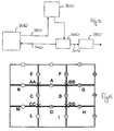
- the filtering unit 350 operates as shown in figure 6. For each pixel to be produced at the output will:
- the median value of three pixels is a new pixel composed by R, G, B components where:
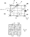
- P1, P2, P3, P4 are the sub-samples located at the same place as were generated by the RGSS 4x algorithm.
- Step3, case 1 will create them as linear combination of the sub-sample generated during step2.
- P1 1/d1*A+1/d2*AA+1/d3*C/(1/d1+1/d2+1/d3)
- P2 1/d1*B+1/d2*BB+1/d3*A/(1/d1+1/d2+1/d3)
- P3 1/d1*D+1/d2*DD+1/d3*B/(1/d1+1/d2+1/d3)
- P4 1/d1*C+1/d2*CC+1/d3*D/(1/d1+1/d2+1/d3) and the pixels sent to the display will be the average of P1, P2, P3, P4.
- Figure 8 shows how for each pixel position (i, j) the grid shown in figure 7 is "composed by sub-pixel".
- Another option to interpolate AA, BB, CC, DD pixels is to use for each of them, four very close and surrounding sub-pixels, and see what image surface shape they represent. There are fourteen of these, in example, corresponding to fourteen possible surface shapes.
- Number Shape type AA is equal to 0 Flat a a a a a a 1 High a a a a b 2 Line a b a or b b a 3 Aligned a a (a+b)/2 b b 4 Low a b b b 5 Twisted edge a a (a+b)/2 b c 6 Valley a b a or (a+b)/2 c a 7 Edge a b b b c 8 Double twisted edge a b (a+b) /2 or (b+c)/2 c b b often better 9 Twisted edge a b (b+c) /2 c c 10 Ridge a c c or (b+c)/2 c b 11 Edge a b (b+c)/2 c d 12 Double twisted edge a b
- Figure 3b shows, by way of further example, a possible alternative to locate the two sub-sample positions per each pixel in any position of the pixel edge.
Landscapes
- Physics & Mathematics (AREA)
- General Physics & Mathematics (AREA)
- Engineering & Computer Science (AREA)
- Theoretical Computer Science (AREA)
- Image Processing (AREA)
- Image Generation (AREA)
Priority Applications (4)
| Application Number | Priority Date | Filing Date | Title |
|---|---|---|---|
| EP04006823A EP1580694A1 (fr) | 2004-03-22 | 2004-03-22 | Rendu d'images avec filtrage adaptif pour anti-aliasing |
| PCT/IB2005/000117 WO2005093664A1 (fr) | 2004-03-22 | 2005-01-14 | Rendu d'image avec filtrage adaptatif pour anti-crenelage |
| US11/526,146 US7876971B2 (en) | 2004-03-22 | 2006-09-21 | Method and system for signal processing, for instance for mobile 3D graphic pipelines, and computer program product therefor |
| US13/013,324 US8224107B2 (en) | 2004-03-22 | 2011-01-25 | Method and system for signal processing, for instance for mobile 3D graphic pipelines, and computer program product therefor |
Applications Claiming Priority (1)
| Application Number | Priority Date | Filing Date | Title |
|---|---|---|---|
| EP04006823A EP1580694A1 (fr) | 2004-03-22 | 2004-03-22 | Rendu d'images avec filtrage adaptif pour anti-aliasing |
Publications (1)
| Publication Number | Publication Date |
|---|---|
| EP1580694A1 true EP1580694A1 (fr) | 2005-09-28 |
Family
ID=34854573
Family Applications (1)
| Application Number | Title | Priority Date | Filing Date |
|---|---|---|---|
| EP04006823A Withdrawn EP1580694A1 (fr) | 2004-03-22 | 2004-03-22 | Rendu d'images avec filtrage adaptif pour anti-aliasing |
Country Status (3)
| Country | Link |
|---|---|
| US (2) | US7876971B2 (fr) |
| EP (1) | EP1580694A1 (fr) |
| WO (1) | WO2005093664A1 (fr) |
Cited By (2)
| Publication number | Priority date | Publication date | Assignee | Title |
|---|---|---|---|---|
| WO2013142506A1 (fr) * | 2012-03-20 | 2013-09-26 | Advanced Micro Devices, Inc. | Procédés et systèmes pour un anticrènelage de qualité améliorée |
| CN104240185A (zh) * | 2013-06-08 | 2014-12-24 | 深圳深讯和科技有限公司 | 图像滤波方法和装置 |
Families Citing this family (26)
| Publication number | Priority date | Publication date | Assignee | Title |
|---|---|---|---|---|
| US7620530B2 (en) * | 2004-11-16 | 2009-11-17 | Nvidia Corporation | System with PPU/GPU architecture |
| US7880747B1 (en) * | 2006-12-13 | 2011-02-01 | Nvidia Corporation | Blend optimizations that are conformant to floating-point rules |
| US8638341B2 (en) * | 2007-10-23 | 2014-01-28 | Qualcomm Incorporated | Antialiasing of two-dimensional vector images |
| JP4569679B2 (ja) * | 2008-07-14 | 2010-10-27 | コニカミノルタビジネステクノロジーズ株式会社 | 解像度変換方法 |
| US8384739B2 (en) * | 2008-09-30 | 2013-02-26 | Konica Minolta Laboratory U.S.A., Inc. | Systems and methods for optimization of pixel-processing algorithms |
| US9336624B2 (en) * | 2008-10-07 | 2016-05-10 | Mitsubishi Electric Research Laboratories, Inc. | Method and system for rendering 3D distance fields |
| US8725476B1 (en) * | 2010-05-04 | 2014-05-13 | Lucasfilm Entertainment Company Ltd. | Applying details in a simulation |
| KR101729556B1 (ko) * | 2010-08-09 | 2017-04-24 | 엘지전자 주식회사 | 입체영상 디스플레이 시스템, 입체영상 디스플레이 장치 및 입체영상 디스플레이 방법, 그리고 위치 추적 장치 |
| KR101682650B1 (ko) * | 2010-09-24 | 2016-12-21 | 삼성전자주식회사 | 프레임 유사성을 이용한 백-페이스 컬링 장치 및 방법 |
| US9183651B2 (en) * | 2010-10-06 | 2015-11-10 | Microsoft Technology Licensing, Llc | Target independent rasterization |
| US8970592B1 (en) | 2011-04-19 | 2015-03-03 | Lucasfilm Entertainment Company LLC | Simulating an arbitrary number of particles |
| US8824834B2 (en) * | 2011-09-23 | 2014-09-02 | Adobe Systems Incorporated | Adaptive sampling guided by multilateral filtering |
| DE112011106062T5 (de) | 2011-12-28 | 2014-09-25 | Intel Corporation | Bildstrom-Pipeline-Controller zur Bereitstellung von Bildprimitiven auf einer Berechnungsstruktur |
| US9230517B2 (en) * | 2012-05-31 | 2016-01-05 | Microsoft Technology Licensing, Llc | Virtual surface gutters |
| US9626792B2 (en) * | 2012-10-16 | 2017-04-18 | Adobe Systems Incorporated | Rendering an infinite plane |
| US9836879B2 (en) * | 2013-04-16 | 2017-12-05 | Autodesk, Inc. | Mesh skinning technique |
| US9401034B2 (en) | 2013-04-30 | 2016-07-26 | Microsoft Technology Licensing, Llc | Tessellation of two-dimensional curves using a graphics pipeline |
| US8982120B1 (en) * | 2013-12-18 | 2015-03-17 | Google Inc. | Blurring while loading map data |
| CA2984819C (fr) * | 2015-05-11 | 2023-10-10 | Pointerra Technologies Pty Ltd | Procede et systeme destines au rendu infographique |
| CN110021054B (zh) * | 2019-04-12 | 2023-07-28 | 青岛九维华盾科技研究院有限公司 | 一种用于斑点迷彩图案设计的斑块赋色方法 |
| GB2586869B (en) * | 2019-09-06 | 2023-02-15 | Imperial College Innovations Ltd | Scene representation using image processing |
| US11508043B2 (en) * | 2020-06-18 | 2022-11-22 | Connaught Electronics Ltd. | Method and apparatus for enhanced anti-aliasing filtering on a GPU |
| US11216916B1 (en) * | 2020-10-09 | 2022-01-04 | Nvidia Corporation | History clamping for denoising dynamic ray-traced scenes using temporal accumulation |
| US11570418B2 (en) | 2021-06-17 | 2023-01-31 | Creal Sa | Techniques for generating light field data by combining multiple synthesized viewpoints |
| US12444017B2 (en) | 2023-07-21 | 2025-10-14 | Nvidia Corporation | Denoising dynamically ray-traced scenes using historical pixel values |
| US12423905B2 (en) | 2023-07-21 | 2025-09-23 | Nvidia Corporation | Denoising dynamically ray-traced scenes using temporal and spatial variances of historical pixel values |
Citations (3)
| Publication number | Priority date | Publication date | Assignee | Title |
|---|---|---|---|---|
| US5287438A (en) * | 1989-11-17 | 1994-02-15 | Digital Equipment Corporation | System and method for drawing antialiased polygons |
| US5668940A (en) | 1994-08-19 | 1997-09-16 | Martin Marietta Corporation | Method and apparatus for anti-aliasing polygon edges in a computer imaging system |
| EP1406447A1 (fr) | 2002-10-04 | 2004-04-07 | STMicroelectronics S.r.l. | Méthode et Système pour le traitement de signaux via une quantification vectorielle perceptive, et programme d'ordinateur |
Family Cites Families (4)
| Publication number | Priority date | Publication date | Assignee | Title |
|---|---|---|---|---|
| US7061507B1 (en) * | 2000-11-12 | 2006-06-13 | Bitboys, Inc. | Antialiasing method and apparatus for video applications |
| US6819332B2 (en) * | 2001-02-27 | 2004-11-16 | 3Dlabs Inc. Ltd. | Antialias mask generation |
| US7764833B2 (en) * | 2003-02-13 | 2010-07-27 | Ati Technologies Ulc | Method and apparatus for anti-aliasing using floating point subpixel color values and compression of same |
| US7050068B1 (en) * | 2003-12-02 | 2006-05-23 | Nvidia Corporation | Generation of jittered sub-pixel samples using programmable sub-pixel offsets |
-
2004
- 2004-03-22 EP EP04006823A patent/EP1580694A1/fr not_active Withdrawn
-
2005
- 2005-01-14 WO PCT/IB2005/000117 patent/WO2005093664A1/fr not_active Ceased
-
2006
- 2006-09-21 US US11/526,146 patent/US7876971B2/en not_active Expired - Lifetime
-
2011
- 2011-01-25 US US13/013,324 patent/US8224107B2/en not_active Expired - Lifetime
Patent Citations (3)
| Publication number | Priority date | Publication date | Assignee | Title |
|---|---|---|---|---|
| US5287438A (en) * | 1989-11-17 | 1994-02-15 | Digital Equipment Corporation | System and method for drawing antialiased polygons |
| US5668940A (en) | 1994-08-19 | 1997-09-16 | Martin Marietta Corporation | Method and apparatus for anti-aliasing polygon edges in a computer imaging system |
| EP1406447A1 (fr) | 2002-10-04 | 2004-04-07 | STMicroelectronics S.r.l. | Méthode et Système pour le traitement de signaux via une quantification vectorielle perceptive, et programme d'ordinateur |
Non-Patent Citations (1)
| Title |
|---|
| BALASUBRAMANIAN R ET AL: "SEQUENTIAL SCALAR QUANTIZATION OF COLOR IMAGES", JOURNAL OF ELECTRONIC IMAGING, SPIE + IS&T, US, vol. 3, no. 1, 1994, pages 45 - 59, XP000420583, ISSN: 1017-9909 * |
Cited By (3)
| Publication number | Priority date | Publication date | Assignee | Title |
|---|---|---|---|---|
| WO2013142506A1 (fr) * | 2012-03-20 | 2013-09-26 | Advanced Micro Devices, Inc. | Procédés et systèmes pour un anticrènelage de qualité améliorée |
| US8928690B2 (en) | 2012-03-20 | 2015-01-06 | Advanced Micro Devices, Inc. | Methods and systems for enhanced quality anti-aliasing |
| CN104240185A (zh) * | 2013-06-08 | 2014-12-24 | 深圳深讯和科技有限公司 | 图像滤波方法和装置 |
Also Published As
| Publication number | Publication date |
|---|---|
| US20110169822A1 (en) | 2011-07-14 |
| US20070071312A1 (en) | 2007-03-29 |
| US7876971B2 (en) | 2011-01-25 |
| WO2005093664A1 (fr) | 2005-10-06 |
| US8224107B2 (en) | 2012-07-17 |
Similar Documents
| Publication | Publication Date | Title |
|---|---|---|
| US8224107B2 (en) | Method and system for signal processing, for instance for mobile 3D graphic pipelines, and computer program product therefor | |
| Sainz et al. | Point-based rendering techniques | |
| US7116337B2 (en) | Transparent depth sorting | |
| US6567083B1 (en) | Method, system, and computer program product for providing illumination in computer graphics shading and animation | |
| US10614619B2 (en) | Graphics processing systems | |
| US6532013B1 (en) | System, method and article of manufacture for pixel shaders for programmable shading | |
| US7215340B2 (en) | Object space EWA splatting of point-based 3D models | |
| Wyman et al. | Penumbra Maps: Approximate Soft Shadows in Real-Time. | |
| Chen et al. | Hardware-accelerated adaptive EWA volume splatting | |
| US20030112237A1 (en) | Method, computer program product and system for rendering soft shadows in a frame representing a 3D-scene | |
| US20020196251A1 (en) | Method and apparatus for culling in a graphics processor with deferred shading | |
| US10089776B2 (en) | Graphics processing systems | |
| Decaudin et al. | Volumetric billboards | |
| JP4732111B2 (ja) | 複数のボクセルを含むボリュームデータセットをレンダリングする方法 | |
| US7525553B2 (en) | Computer graphics processor and method for generating a computer graphics image | |
| Sainz et al. | Points Reloaded: Point-Based Rendering Revisited. | |
| Zhang et al. | Volumetric shadows using splatting | |
| Mara et al. | Lighting deep g-buffers: single-pass, layered depth images with minimum separation applied to indirect illumination | |
| US7385604B1 (en) | Fragment scattering | |
| Zhang et al. | Indirect illumination with efficient monte carlo integration and denoising | |
| EP1759355B1 (fr) | Systeme graphique en 3d avec mappage de texture avant | |
| Marschner et al. | The graphics pipeline | |
| CN101006471B (zh) | 反向纹理映射三维图形系统 | |
| US20050057573A1 (en) | Methods and systems for transparent depth sorting | |
| GB2535792A (en) | Graphic processing systems |
Legal Events
| Date | Code | Title | Description |
|---|---|---|---|
| PUAI | Public reference made under article 153(3) epc to a published international application that has entered the european phase |
Free format text: ORIGINAL CODE: 0009012 |
|
| AK | Designated contracting states |
Kind code of ref document: A1 Designated state(s): AT BE BG CH CY CZ DE DK EE ES FI FR GB GR HU IE IT LI LU MC NL PL PT RO SE SI SK TR |
|
| AX | Request for extension of the european patent |
Extension state: AL LT LV MK |
|
| 17P | Request for examination filed |
Effective date: 20060301 |
|
| AKX | Designation fees paid |
Designated state(s): DE FR GB IT |
|
| 17Q | First examination report despatched |
Effective date: 20071008 |
|
| RAP1 | Party data changed (applicant data changed or rights of an application transferred) |
Owner name: STMICROELECTRONICS SRL |
|
| RAP1 | Party data changed (applicant data changed or rights of an application transferred) |
Owner name: STMICROELECTRONICS SRL |
|
| STAA | Information on the status of an ep patent application or granted ep patent |
Free format text: STATUS: THE APPLICATION IS DEEMED TO BE WITHDRAWN |
|
| 18D | Application deemed to be withdrawn |
Effective date: 20121002 |