EP1580734A2 - Methode d'enregistrement optique, appareil d'enregistrement optique et support d'enregistrement optique - Google Patents
Methode d'enregistrement optique, appareil d'enregistrement optique et support d'enregistrement optique Download PDFInfo
- Publication number
- EP1580734A2 EP1580734A2 EP05251532A EP05251532A EP1580734A2 EP 1580734 A2 EP1580734 A2 EP 1580734A2 EP 05251532 A EP05251532 A EP 05251532A EP 05251532 A EP05251532 A EP 05251532A EP 1580734 A2 EP1580734 A2 EP 1580734A2
- Authority
- EP
- European Patent Office
- Prior art keywords
- recording
- pulse
- optical information
- linear velocity
- information recording
- Prior art date
- Legal status (The legal status is an assumption and is not a legal conclusion. Google has not performed a legal analysis and makes no representation as to the accuracy of the status listed.)
- Withdrawn
Links
Images




Classifications
-
- G—PHYSICS
- G11—INFORMATION STORAGE
- G11B—INFORMATION STORAGE BASED ON RELATIVE MOVEMENT BETWEEN RECORD CARRIER AND TRANSDUCER
- G11B7/00—Recording or reproducing by optical means, e.g. recording using a thermal beam of optical radiation by modifying optical properties or the physical structure, reproducing using an optical beam at lower power by sensing optical properties; Record carriers therefor
- G11B7/004—Recording, reproducing or erasing methods; Read, write or erase circuits therefor
-
- G—PHYSICS
- G11—INFORMATION STORAGE
- G11B—INFORMATION STORAGE BASED ON RELATIVE MOVEMENT BETWEEN RECORD CARRIER AND TRANSDUCER
- G11B7/00—Recording or reproducing by optical means, e.g. recording using a thermal beam of optical radiation by modifying optical properties or the physical structure, reproducing using an optical beam at lower power by sensing optical properties; Record carriers therefor
- G11B7/004—Recording, reproducing or erasing methods; Read, write or erase circuits therefor
- G11B7/006—Overwriting
- G11B7/0062—Overwriting strategies, e.g. recording pulse sequences with erasing level used for phase-change media
-
- G—PHYSICS
- G11—INFORMATION STORAGE
- G11B—INFORMATION STORAGE BASED ON RELATIVE MOVEMENT BETWEEN RECORD CARRIER AND TRANSDUCER
- G11B7/00—Recording or reproducing by optical means, e.g. recording using a thermal beam of optical radiation by modifying optical properties or the physical structure, reproducing using an optical beam at lower power by sensing optical properties; Record carriers therefor
- G11B7/004—Recording, reproducing or erasing methods; Read, write or erase circuits therefor
- G11B7/0045—Recording
Definitions
- the present invention relates to an optical information recording method and an optical information recording apparatus with respect to a recording medium used for optically recording/reproducing data.
- the present invention relates to the improvement of a recording pulse waveform with respect to a medium used for recording data at a plurality of different linear velocities.
- an optical disk As a medium for optically recording data, an optical disk, an optical card, an optical tape, and the like have been proposed and developed. Among them, an optical disk is receiving attention as a medium capable of recording/reproducing data with a large capacity and a high density.
- a recording film of the optical disk is irradiated with laser light of a power level represented by P w that is stronger than a reproducing power (such power level is referred to as a recording power).
- P w a power level represented by P w that is stronger than a reproducing power
- the recording film is irradiated with laser light of a power level represented by P e that is such a degree as to increase the temperature of the recording film to a crystallization temperature or higher and a melting point or lower (such power level is referred to as an erasure power)
- P e a power level represented by P e that is such a degree as to increase the temperature of the recording film to a crystallization temperature or higher and a melting point or lower (such power level is referred to as an erasure power)
- P e a power level represented by P e that is such a degree as to increase the temperature of the recording film to a crystallization temperature or higher and a melting point or lower
- a recorded pattern composed of a mark that is an amorphous region corresponding to a data signal and a space that is a crystalline region is formed on the medium. Then, data is reproduced using the difference in reflectance between the crystalline region and the amorphous region.
- the pulse waveform used in the modulation operation is referred to as a recording pulse.
- the plurality of recording pulses are referred to as a recording pulse train.
- An example of the recording pulse train is represented by (a) of FIG. 14.
- a pulse in a leading portion of the recording pulse train is referred to as a leading pulse 1401.
- Apulse in a trailing portion of the recording pulse train is referred to as a trailing pulse 1403.
- a pulse between the leading pulse 1401 and the trailing pulse 1403 is referred to as a multi-pulse 1402.
- the number of recording pulses constituting the recording pulse train is varied depending upon a recording code length (i.e., a ratio of the length of a recording code with respect to a channel dock period T w ), and the number of recording pulses may be one in the shortest code length.
- a pulse 1404 in the leading portion and a pulse 1405 in the trailing portion also are referred to as a leading pulse and a trailing pulse, respectively.
- a constant linear velocity (CLV) recording system mainly is used. This is a system for recording data over the entire surface of a medium under the condition that the linear velocity, the transfer rate, and the linear density are set to be substantially the same. In this case, the rotation velocity of the medium is varied depending upon the recording/reproducing position (i.e., the radius position) on the medium.
- CAV constant angular velocity
- the linear velocity and the transfer rate are varied depending upon the recording/reproducing position on the medium.
- the irradiation condition of laser light and heating/cooling conditions of the medium are varied depending upon the recording/reproducing position.
- JP 2001-222819 A discloses a method of forming a mark with a recording pulse train, and increasing the duty ratios of the multi-pulse and the trailing pulse (that is, increasing the ratio of a pulse width with respect to a channel clock period) in accordance with an increase in the recording linear velocity.
- JP 2001-76341 A page 5, FIG. 2 discloses a method of increasing the duty ratios of the leading pulse and the multi-pulse in accordance with an increase in the recording linear velocity.
- JP 2001-118245 A discloses a method of forming a mark with a recording pulse train, and increasing the duty ratio of a leading pulse in accordance with an increase in the recording linear velocity.
- a waveform diagram in FIG. 15 in the case of a high linear velocity. That is, in recording at a high linear velocity, a period T w of a channel clock signal in (a) decreases. Based on this channel dock signal, a recording pulse signal in (c) composed of a leading pulse 1501, a multi-pulse 1502, and a trailing pulse 1503 are generated so as to correspond to a modulation signal in (b). The duty ratio between a multi-pulse 1502 and a trailing pulse 1503 is varied as represented by (d) with respect to a recording pulse signal in (c).
- the width of the interval between respective pulses may be smaller than the sum of the rising time and the falling time of laser Consequently, as represented by (e), the light-emission pulse cannot be modulated between the predetermined recording power P w and the predetermined erasure power P e .
- a recording pulse is present also before and after the multi-pulse. Therefore, compared with the recording of the leading pulse and the trailing pulse, thermal energy is likely to be concentrated during recording of the multi-pulse. Consequently, even in the case where the laser power can be modulated between the recording power P w and the erasure power P e using a laser with high performance, when the duty ratio of the multi-pulse is high, a mark center portion corresponding to the portion irradiated by the multi-pulse comes to have a width larger than those of the portions before and after the mark center portion, whereby a phenomenon of distortion in the shape of a mark occurs.
- the duty ratio of the leading pulse when the duty ratio of the leading pulse is increased in accordance with an increase in the recording linear velocity, the duty ratio of the leading pulse becomes smallest when data is recorded at the lowest linear velocity, and consequently, the length of the entire pulse train becomes shortest.
- the relative velocity between the laser spot and the medium in recording at a low linear velocity, the relative velocity between the laser spot and the medium becomes low, so that the cooling speed after melting by laser irradiation becomes low. Consequently, recrystallization proceeds from the periphery of the melted portion, so that the width of a mark front portion becomes small, resulting in a distortion of the mark shape that degrades the quality of a reproduced signal.
- an object of the present invention to provide an optical information recording method, an optical information recording apparatus, and an optical information recording medium capable of recording/reproducing data of satisfactory signal quality stably over a wide linear velocity range with respect to the same medium.
- a first optical information recording method of the present invention includes: forming a recording pulse for driving a laser so that a length of a mark or a space to be recorded on an optical information recording medium corresponds to a recording code length of data; forming the recording pulse as a recording pulse train having respective pulse heights corresponding to a plurality of power levels including a recording power P w and an erasure power P e ; composing the recording pulse train of a plurality of pulses including a multi-pulse and a trailing pulse with respect to at least one kind of the recording code length; and irradiating the optical information recording medium at a plurality kinds of linear velocities with laser light based on the recording pulse to vary optical characteristics of a photosensitive recording film, thereby forming the mark or the space.
- a mark without distortion can be formed at a low linear velocity, and insufficient erasure during overwrite can be eliminated at a high linear velocity. Therefore, data can be recorded with satisfactory signal quality over a wide linear velocity range.
- T L1 T M1 . According to this configuration, it is not necessary to generate and correct only a trailing pulse independently at the linear velocity v1, so that the configuration of the apparatus can be simplified.
- a power level P w of a back portion of the recording pulse may be set to be different from a power level P b in a center portion of the recording pulse, hereby forming a trailing pulse with respect to at least one recording code length.
- the trailing pulse width T L may be controlled so as to increase (T I /T) in accordance with an increase in the linear velocity v. This enables the light-emission waveform at an intermediate linear velocity to be determined easily.
- a second optical information recording method of the present invention includes: forming a recording pulse for driving a laser so that a length of a mark or a space to be recorded on an optical information recording medium corresponds to a recording code length of data; forming the recording pulse as a recording pulse train having respective pulse heights corresponding to a plurality of power levels including a recording power P w and an erasure power P e ; composing the recording pulse train of a plurality of pulses including a leading pulse with respect to at least one kind of the recording code length; and irradiating the optical information recording medium at a plurality kinds of linear velocities with laser light based on the recording pulse to vary optical characteristics of a photosensitive recording film, thereby forming the mark or the space.
- a mark without distortion can be formed at a low linear velocity, so that data can be recorded with satisfactory signal quality over a wide linear velocity range.
- the recording pulse train includes a multi-pulse continuing to the leading pulse, and when multi-pulse widths at the linear velocities v1, v2 respectively are T M1 , T M2 , ((T M1 /T w1 )/(T M2 /T w2 )) ⁇ ((T S1 /T w1 )/(T S2 /T w2 )) is satisfied.
- a power level P w of a front portion of the recording pulse may be set to be different from a power level P b in a center portion of the recording pulse, hereby forming a leading pulse with respect to at least one recording code length.
- the leading pulse width Ts can be controlled so as to decrease (T S /T) in accordance with an increase in the linear velocity v.
- the first or second optical information recording method it is preferable that data is recorded on an optical information recording medium by a CAV recording system. This enables data to be recorded with satisfactory signal quality irrespective of the recording/reproducing position in a medium.
- a power level between the recording pulses is set to be different from the erasure power P e . This enables the cooling speed during recording to be controlled optimally in accordance with a linear velocity, so that data can be recorded with more satisfactory signal quality.
- a power level between the recording pulses at the linear velocity v2 is set to be higher than a power level between the recording pulses at the linear velocity v1. According to this configuration, the cooling speed during recording does not become excessive at a high linear velocity. Therefore, insufficient erasure during overwrite decreases, and data can be recorded with more satisfactory signal quality.
- a first optical information recording apparatus of the present invention includes: a linear velocity setting circuit for setting a plurality of different kinds of linear velocities in recording on an optical information recording medium; a recording pulse generation circuit for generating a recording pulse in accordance with a setting result of the linear velocity setting circuit; and a laser driving circuit for radiating laser light based on the recording pulse.
- the recording pulse generation circuit forms a recording pulse for driving a laser so that a length of a mark or a space to be recorded on an optical information recording medium corresponds to a recording code length of data, forms the recording pulse as a recording pulse train having respective pulse heights corresponding to a plurality of power levels including a recording power P w and an erasure power P e , and composes the recording pulse train of a plurality of pulses including a multi-pulse and a trailing pulse with respect to at least one kind of the recording code length.
- the recording pulse generation circuit controls the trailing pulse widths so as to satisfy the following formulas:
- a mark without distortion can be formed at a low linear velocity, and insufficient erasure during overwrite can be eliminated at a high linear velocity. Therefore, data can be recorded with satisfactory signal quality over a wide linear velocity range.
- a power level P w of a back portion of the recording pulse may be set to be different from a power level P b in a center portion of the recording pulse, hereby forming a trailing pulse with respect to at least one recording code length.
- the recording pulse generation circuit controls the trailing pulse widths so as to increase (T L /T) in accordance with an increase in the linear velocity v. This enables the light-emission waveform at an intermediate linear velocity to be determined easily.
- a second optical information recording apparatus of the present invention includes: a linear velocity setting circuit for setting a plurality of different kinds of linear velocities in recording on an optical information recording medium; a recording pulse generation circuit for generating a recording pulse in accordance with a setting result of the linear velocity setting circuit; and a laser driving circuit for radiating laser light based on the recording pulse.
- the recording pulse generation circuit forms a recording pulse for driving a laser so that a length of a mark or a space to be recorded on an optical information recording medium corresponds to a recording code length of data, forms the recording pulse as a recording pulse train having respective pulse heights corresponding to a plurality of power levels including a recording power P w and an erasure power P e , and composes the recording pulse train of a plurality of pulses including a leading pulse with respect to at least one kind of the recording code length.
- the recording pulse generation circuit controls the leading pulse widths so as to satisfy the following formulas:
- a mark without distortion can be formed at a low linear velocity, so that data can be recorded with satisfactory signal quality over a wide linear velocity range.
- the recording pulse train includes a multi-pulse continuing to the leading pulse, and when multi-pulse widths at the linear velocities v1, v2 respectively are T M1 , T M2 , the recording pulse generation circuit controls the leading pulse widths so as to satisfy ((T M1 T w1 )/(T M2 /T w2 )) ⁇ (T S1 /T w1 )/(T S2 /T w2 )).
- a power level P w of a front portion of the recording pulse may be set to be different from a power level P b in a center portion of the recording pulse, hereby forming a leading pulse with respect to at least one recording code length.
- the recording pulse generation circuit controls the trailing pulse widths so as to satisfy (T L1 /T w1 ) ⁇ (T L2 /T w2 ).
- the recording pulse generation circuit controls the leading pulse width Ts so as to decrease (Ts/T) in accordance with an increase in the linear velocity v. This enables the light-emission waveform at an intermediate linear velocity to be determined easily.
- an optical information recording medium of the present invention is used for recording data by the above-mentioned first or second optical information recording method, and information representing values of T L1 and T L2 or information representing values of T S1 and T S2 is recorded on the optical information recording medium.
- the optical information recording medium is used for recording data by an optical information recording method, in which when a channel clock period is T, and a trailing pulse width is T L at a linear velocity v between the linear velocity v1 and the linear velocity v2, the trailing pulse width T L is controlled so as to increase (T L /T) in accordance with an increase in the linear velocity v, and information determining T L is recorded on the optical information recording medium.
- the optical information recording medium is used for recording data by an optical information recording method, in which when a channel dock period is T, and a leading pulse width is Ts at a linear velocity v between the linear velocity v1 and the linear velocity v2, the leading pulse width Ts is controlled so as to decrease (T S /T) in accordance with an increase in the linear velocity, and information determining Ts is recorded on the optical information recording medium.
- the pulse width can be determined in accordance with a linear velocity.
- FIG. 1 shows the optical information recording/reproducing apparatus
- the embodiment of the present invention is characterized by the configuration of a portion corresponding to a recording apparatus in this optical information recording/reproducing apparatus.
- the basic configuration of the optical information recording apparatus shown in FIG. 1 is common to the following respective embodiments.
- Reference numeral 1 denotes an optical disk for recording/reproducing data
- reference numeral 2 denotes a system control circuit for controlling the entire recording/reproducing apparatus.
- a modulation circuit 3 Based on a signal supplied from a system control circuit 2, a modulation circuit 3 generates a binarized modulation signal 12 in accordance with data to be recorded.
- a recording pulse generation circuit 4 generates a recording pulse signal for driving a laser in accordance with the modulation signal 12 output from the modulation circuit 3.
- Each recording pulse signal is output as a recording pulse signal 14 with its width and edge position corrected by a recording pulse correction circuit 5.
- a laser driving circuit 6 modulates a current for driving a laser in an optical head 7 based on a recording pulse signal 14 output by the recording pulse correction circuit 5, and a power setting signal 16 supplied from the system control circuit 2.
- An optical head 7 focuses laser light 15 and irradiates the optical disk 1 with the laser light 15.
- the optical disk 1 has its linear velocity (i.e., rotation number) controlled by a linear velocity setting circuit 8.
- Reference numeral 9 denotes a spindle motor for rotating the optical disk 1.
- a reproduced signal based on light reflected from the optical disk 1 is subjected to waveform processing by a reproduced signal processing circuit 10, and supplied to a demodulation circuit 11 for obtaining reproduced data.
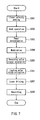
- Embodiment 1 Next, the optical information recording method and the optical information recording apparatus in Embodiment 1 will be described with reference to a flow chart of FIG. 2 and operation diagrams of FIGS. 3 to 6.
- FIG. 2 shows a recording procedure according to the optical information recording method of Embodiment 1.
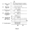
- FIG. 3 shows a signal waveform and a recorded pattern on a track in the case of recording data with a lower linear velocity according to the optical information recording method of Embodiment 1.
- FIGS. 4 and 5 show a signal waveform and a recorded pattern when the width of a trailing pulse is varied in the case of recording data with a low linear velocity.
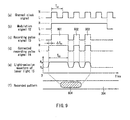
- FIG. 6 shows a signal waveform and a recorded pattern in the case of recording data with a high linear velocity.
- FIGS. 3 to 6 show an operation by exemplifying the case where a mark with a code length 5T is recorded.
- T is equal to a channel clock period T w .
- a recording pulse train composed of three recording pulses in total is used for recording the code length 5T.
- the number of recording pulses and/or the full length of a recording pulse train are varied in accordance with the increase/decrease in a code length.
- FIGS. 3 and 6 (a) represents a channel clock signal, (b) represents a waveform of the modulation signal 12 (see FIG. 1), (c) represents a waveform of the recording pulse signal 13, (d) represents a waveform of the corrected recording pulse signal 14, and (e) represents a light-emission waveform of the laser light 15.
- the recording pulse signals 13 respectively are composed of a recording pulse train including leading pulses 301, 601, multi-pulses 302, 602, and trailing pulses 303, 603.
- (f) represents a recorded pattern on a track 304 on which a mark 305 or 604 is recorded with the laser light 15.
- FIGS. 4 and 5 (a) represents the light-emission waveform of the laser light 15, and (b) represents a recorded pattern on the track 304 on which the mark 401 or 501 is recorded.
- Step S201 a linear velocity setting step
- the linear velocity setting circuit 8 controls the number of rotations of the spindle motor 9 based on an instruction from the system control circuit 2, whereby the optical disk 1 is rotated at a predetermined linear velocity.
- a seek operation step S202
- the optical head 7 see FIG. 1 is positioned in a predetermined recording region on the optical disk 1.
- the system control circuit 2 determines the optimum recording power, erasure power, and the like at this linear velocity, and outputs the power setting signal 16 to the laser driving circuit 6. These power levels can be determined by test recording with respect to the optical disk 1. If information representing a power level is recorded in a control track region of the optical disk 1, the power level may be determined by reading the information.
- a modulation step (S204) recording data from the system control circuit 2 is modulated by the modulation circuit 3 based on the channel clock signal represented by (a) of FIG. 3.
- the modulation circuit 3 outputs the modulation signal 12 represented by FIG. 3(b).
- the recording pulse generation circuit 4 outputs the recording pulse signal 13 represented by (c) of FIG. 3 based on the modulation signal.
- the recording pulse correction circuit 5 corrects the width and edge position of each recording pulse constituting the recording pulse signal 13, and outputs the corrected recording pulse signal 14 to the laser driving circuit 6.
- the trailing pulse is not corrected.
- the laser driving circuit 6 modulates the power level of the laser light 15.
- the power level is determined by the corrected recording pulse signal 14 and the power setting signal 16 from the system control circuit 2. More specifically, in the case where a recording pulse train signal is H, light is emitted at the recording power P w , and in the case where a recording pulse train signal is L, light is emitted at the erasure power P e . Consequently, the light-emission waveform of the laser light 15 has its power level varied as represented by (e) of FIG. 3.
- a mark 305 corresponding to the code length 5T is formed on the recording track 304 with the laser light 15, as shown in the recorded pattern in (f) of FIG. 3.
- T L1 is set to be smaller than T w1 . This will be described with reference to FIGS. 4 and 5.
- FIGS. 4 and 5 show the states where the molten region and the mark shape are varied depending upon a trailing pulse width T L1 in the case of recording at a low linear velocity.
- FIG. 4 shows a laser light-emission waveform (a) and a recorded pattern (b) in the case of recording with a trailing pulse width T La (corresponding to the present embodiment)
- FIG. 5 shows a laser light-emission waveform (a) and a recorded pattern (b) in the case of recording with a larger trailing pulse width T Lb .
- (a) to (e) of FIG. 6 show the signal waveform of each part of the apparatus in the case of recording at a high linear velocity v2 (i.e., recording at a high transfer rate) based on the present embodiment, and (f) of FIG. 6 shows the recorded pattern on the track.
- v2 i.e., recording at a high transfer rate
- This configuration is different from the case of a low linear velocity v1 in that, in the trailing pulse correction step (S206) shown in FIG. 2, the trailing pulse width T L2 is enlarged by ⁇ T L2 at the trailing edge, whereby the ratio of the trailing pulse width T L2 with respect to the channel clock period T w2 is increased. Consequently, more heat is given when a mark back portion is formed, and the mark back portion is cooled gradually after melting. This can prevent an amorphous region from becoming too stable due to the excessive cooling speed during formation of the mark back portion.
- a high linear velocity at which the relative velocity between the laser spot and the medium increases insufficient erasure does not occur during overwriting, and data can be recorded with satisfactory signal quality.
- the duty ratio of the multi-pulses 302, 602 is not varied. Therefore, even when the channel clock period T w2 becomes smaller, the width between the recording pulses does not become extremely small. Consequently, even in the case of a high linear velocity, laser light can be subjected to modulation and light-emission operations stably between the respective power levels. Furthermore, since heat energy is not given excessively during recording of the mark center portion, the distortion of a mark in which the mark center portion becomes wide can be suppressed.
- the ratio of the width of the trailing pulse with respect to the channel clock period is varied between the cases of the low linear velocity v1 and the high linear velocity v2 as represented by the relationships in (e) of FIGS. 3 and 6, whereby the trailing pulse width is set to be relatively small at a low linear velocity, and to be relatively large at a high linear velocity. This enables a mark without distortion to be formed, and eliminates insufficient erasure during overwriting at a high linear velocity.
- the duty ratio of a multi-pulse is set to be constant between the low linear velocity and the high linear velocity
- the duty ratio of the multi-pulse also may be increased along with an increase in a linear velocity.
- the increase ratio of a multi-pulse width with respect to the increase ratio of a linear velocity is set to be smaller than that of the trailing pulse width.
- the multi-pulse width refers to the width of each individual pulse forming a multi-pulse. ((T M2 /T w2 )/(T M1 /T w1 )) ⁇ ((T L2 /T w2 )/(T L1 /T w1 ))
- the duty ratio of a multi-pulse is set to be constant.
- the linear velocities v1 and v2 are extracted so as to define the relative relationship with respect to two kinds of linear velocities among a plurality of kinds of linear velocities. That is, the invention is not limited to the case where only two kinds of linear velocities are used. More specifically, in the case where three or more kinds of linear velocities are used, the method of the present embodiment is applicable similarly.
- the trailing pulse width T L1 is set to be equal to the multi-pulse width T M1 at the lowest linear velocity v1
- the trailing pulse at the linear velocity v1 can be generated in the same way as in the multi-pulse.
- it is not necessary to generate and correct the trailing pulse alone independently at the linear velocity v1 so that there is a further advantage in that the configuration of the apparatus can be simplified.
- Embodiment 2 Next, an optical information recording method and an optical information recording apparatus in Embodiment 2 will be described with reference to the flow chart of FIG. 7 and the operation diagrams of FIGS. 8 to 11.
- the basic configuration of the optical information recording apparatus in the present embodiment is the same as that of Embodiment 1 shown in FIG. 1.
- FIG. 7 shows a recording procedure according to the optical information recording method of the present embodiment.
- FIG. 8 shows a signal waveform and a recorded pattern on a track in the case of recording with a high linear velocity by the optical information recording method of the present embodiment.
- FIG. 9 shows a signal waveform and a recorded pattern in the case of recording with a low linear velocity.
- FIGS. 10 and 11 respectively show a signal waveform and a recorded pattern when the width of a leading pulse is varied in the case of recording with a low linear velocity.
- FIGS. 8 to 11 show an operation exemplifying the case where a mark with the code length 5T is recorded in the same way as in FIGS. 3 to 6.
- FIGS. 8 and 9 (a) represents a channel clock signal, (b) represents a waveform of a modulation signal 12 (see FIG. 1), (c) represents a waveform of a recording pulse signal 13, (d) represents a waveform of a corrected recording pulse signal 14, and (e) represents a light-emission waveform of laser light 15.
- the recording pulse signals 13 respectively are composed of a recording pulse train including leading pulses 801, 901, multi-pulses 802, 902, and trailing pulses 803, 903.
- (f) represents a recorded pattern on a track 304 after a mark 804 or 904 is recorded with the laser light 15.
- FIGS. 10 and 11 (a) represents a light-emission waveform of the laser light 15, and (b) represents a recorded pattern on the track 304 where a mark 1001 or 1101 is recorded.
- the optical head 7 is placed in a predetermined recording region on the optical disk 1 (see FIG. 1) rotated at a predetermined linear velocity in the linear velocity setting step (S201) and the seek operation step (S202).
- the system control circuit 2 determines appropriate recording power, erasure power, and the like at this linear velocity, and outputs a power setting signal 16 to the laser driving circuit 6. These power levels can be determined by test recording with respect to the optical disk 1. If information representing a power level is recorded in a control track region of the optical disk 1, the power level may be determined by reading the information.
- the recording data from the system control circuit 2 is modified by the modulation circuit 3 based on the channel clock signal represented by (a) of FIG. 8.
- the modulation circuit 3 sends the modulation signal 12 represented by (b) of FIG. 8.
- the recording pulse generation circuit 4 outputs a recording pulse signal 13 represented by (c) of FIG. 8 based on the modulation signal. Hitherto, the operation is the same as that in Embodiment 1.
- the recording pulse correction circuit 5 corrects the width and edge position of each recording pulse constituting the recording pulse signal 13, and outputs a corrected recording pulse signal 14 to the laser driving circuit 6.
- the leading pulse is not corrected.
- the laser driving circuit 6 modulates the power level of the laser light 15.
- the power level is determined by the corrected recording pulse signal 14 and the power setting signal 16 from the system control circuit 2. More specifically, in the case where the recording pulse train signal is H, light is emitted at a recording power P w , and light is emitted as an erasure power P e in the case where the recording pulse train signal is L. Consequently, as represented by (e) of FIG. 8, the light-emission waveform of the laser light 15 has the power level varied as represented by (e) of FIG. 8.
- a mark 804 corresponding to the code length 5T is formed on the recording track 304 with the laser light 15.
- FIG. 9 shows signal waveforms of respective parts of the apparatus, and (f) of FIG. 9 shows a recorded pattern on a track, in the case of recording at a low linear velocity v1 (i.e., recording at a low transfer rate) based on the present embodiment.
- v1 linear velocity
- the difference from the case of a high linear velocity lies in that, in the leading pulse width correction step (S701), the leading pulse width Tsi is enlarged by ⁇ T S1 at the leading edge, and the ratio of the leading pulse width T S1 with respect to the channel clock period T w1 is set to be large. This prevents the recrystallization after melting from proceeding during recording at a low linear velocity v1 to decrease the width of a mark front portion. This will be described with reference to FIGS. 10 and 11.
- FIGS. 10 and 11 respectively show a state where a molten region and a mark shape are varied depending upon the leading pulse width Tsi in the case of recording at a low linear velocity.
- (a) represents a laser light-emission waveform and (b) represents a recorded pattern in the case of recording with a small leading pulse width T Sc .
- (a) represents a laser light-emission waveform and (b) represents a recorded pattern in the case of recording with a large leading pulse width T Sd (corresponding to the present embodiment).
- the temperature after melting is unlikely to decrease since a laser continues to emit light with a recording power (i.e., the state of a high irradiation energy continues) even after the mark front portion is formed. Therefore, as represented by (b) of FIG. 10, the width of a mark 1001 to be formed tends to be smaller than that of a molten region 1002. This tendency is exhibited more remarkably as data is recorded at a lower linear velocity. Consequently, a width W Tc of a mark front portion and a width W Lc of a mark back portion become different, and the shape of a mark to be formed is distorted, whereby the signal quality when the mark is reproduced decreases.
- the summary of the present embodiment is that the lower linear velocity v1 and the high linear velocity v2 are set so as to satisfy the following Conditional Formula (3) (T S1 /T w1 ) > (T S2 /T w2 )
- the ratio of the leading pulse width with respect to the channel clock period is varied as represented by the relationships in (e) of FIG. 8 and (e) of FIG. 9, whereby the leading pulse width is increased relatively at a low linear velocity and decreased relatively at a high linear velocity. This enables a mark without distortion to be formed at a low linear velocity, so that data can be recorded with satisfactory signal quality over a wide linear velocity range.
- the duty ratio of a multi-pulse also may be increased in accordance with a decrease in a linear velocity.
- the increase ratio of the multi-pulse width with respect to the decrease ratio of the linear velocity is set to be smaller with respect to the increase ratio of the leading pulse.
- the case where data is recorded at two kinds of linear velocities: a low linear velocity v1 and a high linear velocity v2 has been described.
- the linear velocity and the transfer rate are varied continuously depending upon the recording/reproducing position on a medium.
- the present embodiment is an example in which the optical information recording method of Embodiment 1 or 2 is configured in such an embodiment.
- FIG. 12 shows an example of setting a trailing pulse width when data is recorded with a linear velocity varied continuously in a range of v1 to v2 in Embodiment 1.
- the linear velocity v1 light is emitted with the light-emission waveform of laser light represented by (e) of FIG. 3, i.e., at the ratio (T L1 /T w1 ) of the width of the trailing pulse with respect to the channel clock period.
- the linear velocity v2 light is emitted with the light-emission waveform represented by (e) of FIG. 6, i.e., at the ratio (T L2 /T w2 ) of the trailing pulse with respect to the channel clock period.
- the ratio of the trailing pulse width with respect to the channel clock period is varied smoothly between the ratio (T L1 /T w1 ) at the linear velocity v 1 and the ratio (T L2 /T w2 ) at the linear velocity v2.
- This variation may be a linear variation as shown in FIG. 12, a smoothly curved monotonous variation, or a monotonous variation in stages. It is desirable that the ratio of the trailing pulse width with respect to the channel clock period is set to increase in accordance with an increase in a linear velocity.
- FIG. 13 shows an example of setting a leading pulse width when data is recorded with a linear velocity varied continuously in a range of v1 to v2 in Embodiment 2.
- the ratio of the leading pulse width with respect to the channel clock period is varied smoothly between the ratio (T S1 /T w1 ) at the linear velocity v1 and the ratio (T S2 /T w2 ) at the linear velocity v2.
- it is desirable that the ratio of the leading pulse width with respect to the channel clock period is set to decrease in accordance with an increase in a linear velocity.
- a simplest method for determining the recording pulse width in a range between the linear velocities v1 and v2 is to determine the recording pulse width by interpolating the recording pulse width at a desired linear velocity based on the recording pulse widths at respective linear velocities v1, v2.
- a recording pulse train is configured by providing a multi-pulse between the leading pulse and the trailing pulse
- the recording pulse also can be configured with a region between the leading pulse and the trailing pulse set to be a constant power level P b . Even in this case, if the leading pulse width and the trailing pulse width are varied in the relationship as in each of the above-mentioned embodiments, data similarly can be recorded with satisfactory signal quality.
- the power level P b between the leading pulse and the trailing pulse desirably is fixed preferably in order to simplify the configuration of the apparatus.
- the power level P b also can be varied in accordance with a change in a linear velocity.
- the change ratio of the power level P b with respect to the change ratio of the linear velocity is set to be smaller than that of the trailing pulse width.
- the duty ratio between the power level ratio ⁇ and the multi-pulse becomes equivalent in terms of energy.
- P b1 represents a power level in a center portion of the recording pulse at the linear velocity v1
- P b2 represents a power level in a center portion of the recording pulse at the linear velocity v2.
- the power level P b is set so as to satisfy the following Conditional Formula (8) with respect to the power level ratios ⁇ 1, ⁇ 2 ( ⁇ 2/ ⁇ 1) ⁇ ((T L2 /T w2 )/(T L1 /T w1 ))
- the power level P b is set so as to satisfy the following Conditional Formula (9) ( ⁇ 2/ ⁇ 1) ⁇ ((T S1 /T w1 )/(T S2 /T w2 ))
- one of the trailing pulse width and the leading pulse width is varied with respect to the linear velocity.
- both the pulse widths are varied simultaneously as described above. In this case, there is an advantage that data can be recorded with satisfactory signal quality in a wide range of a linear velocity.
- the optimum values of the leading pulse width or the trailing pulse width at the linear velocities v1 and v2 may be determined from test recording.
- the best pulse width can be determined in accordance with the kind of a medium and the state of an apparatus.
- the pulse width in accordance with the linear velocity can be determined.
- the information on the power level may be recorded on a medium by the optical information recording apparatus or may be recorded previously in the course of production of a medium.
- the power level of a laser light-emission wave is varied between two levels P w and P e .
- the power level may be varied among at least three levels.
- the power level (also referred to as a bottom level) between respective recording pulses may be set to be higher than P e or lower than P e .
- the power level between the recording pulses is set so as to increase in accordance with the increase in a linear velocity, which is preferable in that the cooling speed does not become excessive during recording at a high linear speed, and insufficient erasure during overwriting is eliminated.
- the modulation system of a recording pulse, the length, position, and the like of each pulse are not limited to those described in the embodiments, and may be set appropriately in accordance with recording conditions and a medium. Furthermore, in order to avoid the influence of thermal interference between marks, the edge portion of a recording pulse also can be corrected.
- the above method is applicable to any medium such as an optical disk made of a phase-change material, a magnetooptical material, a coloring material, or the like, as long as optical characteristics are varied between a mark and a space.
- the same effects as those described above can be obtained even when the optical information recording method, the optical information recording apparatus, and the optical information recording medium of the present invention are applied to a personal computer, a server, a recorder, and the like.
Landscapes
- Optical Head (AREA)
- Optical Recording Or Reproduction (AREA)
Applications Claiming Priority (2)
| Application Number | Priority Date | Filing Date | Title |
|---|---|---|---|
| JP2004072544 | 2004-03-15 | ||
| JP2004072544 | 2004-03-15 |
Publications (2)
| Publication Number | Publication Date |
|---|---|
| EP1580734A2 true EP1580734A2 (fr) | 2005-09-28 |
| EP1580734A3 EP1580734A3 (fr) | 2006-12-20 |
Family
ID=34858338
Family Applications (1)
| Application Number | Title | Priority Date | Filing Date |
|---|---|---|---|
| EP05251532A Withdrawn EP1580734A3 (fr) | 2004-03-15 | 2005-03-15 | Methode d'enregistrement optique, appareil d'enregistrement optique et support d'enregistrement optique |
Country Status (5)
| Country | Link |
|---|---|
| US (2) | US20050213464A1 (fr) |
| EP (1) | EP1580734A3 (fr) |
| KR (1) | KR20060043655A (fr) |
| CN (1) | CN1677514A (fr) |
| TW (1) | TW200540831A (fr) |
Families Citing this family (3)
| Publication number | Priority date | Publication date | Assignee | Title |
|---|---|---|---|---|
| JP2012069215A (ja) * | 2010-09-24 | 2012-04-05 | Hitachi-Lg Data Storage Inc | 光ディスク装置、情報記録方法及び光ディスク |
| US8929838B2 (en) * | 2011-06-30 | 2015-01-06 | Motorola Mobility Llc | System and methods for adaptive antenna optimization |
| US9564676B2 (en) | 2011-06-30 | 2017-02-07 | Google Technology Holdings LLC | System and methods for adaptive antenna optimization |
Family Cites Families (18)
| Publication number | Priority date | Publication date | Assignee | Title |
|---|---|---|---|---|
| JP2605577B2 (ja) * | 1993-03-19 | 1997-04-30 | ヤマハ株式会社 | 光ディスク記録装置 |
| DE19612823C2 (de) * | 1995-03-31 | 2001-03-01 | Mitsubishi Chem Corp | Optisches Aufzeichnungsverfahren |
| US5732062A (en) * | 1995-10-16 | 1998-03-24 | Ricoh Company, Ltd. | Information recording apparatus, method and computer program product |
| GB2336463B (en) * | 1998-04-16 | 2000-07-05 | Ricoh Kk | Optical recording method for a rewritable phase-change optical recording medium |
| JP4063978B2 (ja) * | 1998-07-03 | 2008-03-19 | 株式会社リコー | 情報記録方法 |
| JP2000132836A (ja) * | 1998-10-28 | 2000-05-12 | Tdk Corp | 光記録方法 |
| JP2001067669A (ja) * | 1999-08-31 | 2001-03-16 | Sony Corp | 記録装置、記録方法 |
| US6771577B2 (en) * | 1999-09-06 | 2004-08-03 | Ricoh Company, Ltd. | Information recording apparatus and method |
| US6459666B1 (en) * | 1999-09-06 | 2002-10-01 | Ricoh Company, Ltd. | Information recording apparatus and method |
| JP3839213B2 (ja) * | 2000-02-08 | 2006-11-01 | 株式会社リコー | 相変化型光記録媒体の記録方法および記録再生装置 |
| JP3816304B2 (ja) * | 2000-05-31 | 2006-08-30 | 株式会社リコー | 光ディスク装置 |
| JP3793437B2 (ja) * | 2000-10-10 | 2006-07-05 | Tdk株式会社 | 光記録方法および光記録媒体 |
| US6664526B2 (en) * | 2000-11-15 | 2003-12-16 | Ricoh Company, Ltd. | Optical information recording employing improved recording power control scheme |
| JP3921046B2 (ja) * | 2000-12-07 | 2007-05-30 | 株式会社日立製作所 | 情報記録方法及び光ディスク装置 |
| JP2002245624A (ja) * | 2001-02-14 | 2002-08-30 | Tdk Corp | 光記録方法、光記録装置および光記録媒体 |
| CN1287362C (zh) * | 2002-02-13 | 2006-11-29 | 三菱化学媒体株式会社 | 可改写光记录媒体和光记录方法 |
| JP3820181B2 (ja) * | 2002-05-10 | 2006-09-13 | 株式会社リコー | 記録ストラテジ生成方法及び光情報記録媒体 |
| AU2003251171A1 (en) * | 2002-08-03 | 2004-02-23 | Samsung Electronics Co., Ltd. | Information storage medium and method of recording and/or reproducing with respect to the medium |
-
2005
- 2005-03-14 TW TW094107631A patent/TW200540831A/zh unknown
- 2005-03-15 CN CNA2005100558466A patent/CN1677514A/zh active Pending
- 2005-03-15 KR KR1020050021472A patent/KR20060043655A/ko not_active Withdrawn
- 2005-03-15 US US11/080,142 patent/US20050213464A1/en not_active Abandoned
- 2005-03-15 EP EP05251532A patent/EP1580734A3/fr not_active Withdrawn
-
2008
- 2008-11-13 US US12/270,325 patent/US20090067308A1/en not_active Abandoned
Also Published As
| Publication number | Publication date |
|---|---|
| KR20060043655A (ko) | 2006-05-15 |
| US20090067308A1 (en) | 2009-03-12 |
| EP1580734A3 (fr) | 2006-12-20 |
| CN1677514A (zh) | 2005-10-05 |
| US20050213464A1 (en) | 2005-09-29 |
| TW200540831A (en) | 2005-12-16 |
Similar Documents
| Publication | Publication Date | Title |
|---|---|---|
| EP0977184B1 (fr) | Procédé et circuit d'écriture adaptive pour un appareil d'enregistrement optique à haute densité | |
| US7489614B2 (en) | Recording method and media having marks and spaces with lengths defined by a predetermined modulation method | |
| US20080310270A1 (en) | Information recording method and apparatus with suppressed mark edge jitters | |
| JP2010140635A (ja) | 光学的情報記録方法、光学的情報記録装置および光学的情報記録媒体 | |
| EP1347444B1 (fr) | Procédé et appareil d'enregistrement de données sur un support d'enregistrement optique | |
| CN1926611B (zh) | 光学性的信息记录方法、信息记录介质、信息记录装置 | |
| US20050030870A1 (en) | Method and device for recording marks in recording layer of an optical storage medium | |
| US7016282B2 (en) | Information recording method and optical disk unit | |
| JP2003203337A (ja) | 情報記録方法及び情報記録装置 | |
| US20090067308A1 (en) | Optical information recording method, optical information recording apparatus, and optical information recording medium | |
| US7173893B2 (en) | Optical recording medium, method of recording information to an optical recording medium, and information recording apparatus | |
| US20040190431A1 (en) | Optical recording medium, method and apparatus for recording data thereon | |
| US20070183288A1 (en) | Method and device for recording marks in an information layer of an optical record carrier | |
| JP2005302271A (ja) | 光学的情報記録方法、光学的情報記録装置および光学的情報記録媒体 | |
| JP4348384B2 (ja) | 光学的データ記録方法 | |
| JPH064867A (ja) | 光学情報記録方法と光学的情報記録再生装置 | |
| JP2002298348A (ja) | 光学的情報記録再生方法及び光学的情報記録再生装置 | |
| JP2005032295A (ja) | 情報の記録方法 | |
| JP2005011496A (ja) | 情報記録媒体の記録装置、情報記録媒体、情報記録媒体の記録方法、情報記録媒体の記録用プログラム及びコンピュータ読み取り可能な記録媒体 | |
| WO2000074045A1 (fr) | Dispositif et procede d'enregistrement d'informations optiques, et support d'enregistrement d'informations optiques | |
| JP2003099930A (ja) | 光記録媒体への情報記録方法、情報記録装置及び光記録媒体 | |
| JPH04205919A (ja) | 情報の記録方法及び情報記録装置 | |
| KR20040028317A (ko) | 광 기록매체에 데이터를 기록하는 방법 및 그 장치 | |
| JP2008010146A (ja) | 光学的データ記録方法 |
Legal Events
| Date | Code | Title | Description |
|---|---|---|---|
| PUAI | Public reference made under article 153(3) epc to a published international application that has entered the european phase |
Free format text: ORIGINAL CODE: 0009012 |
|
| AK | Designated contracting states |
Kind code of ref document: A2 Designated state(s): AT BE BG CH CY CZ DE DK EE ES FI FR GB GR HU IE IS IT LI LT LU MC NL PL PT RO SE SI SK TR |
|
| AX | Request for extension of the european patent |
Extension state: AL BA HR LV MK YU |
|
| PUAL | Search report despatched |
Free format text: ORIGINAL CODE: 0009013 |
|
| AK | Designated contracting states |
Kind code of ref document: A3 Designated state(s): AT BE BG CH CY CZ DE DK EE ES FI FR GB GR HU IE IS IT LI LT LU MC NL PL PT RO SE SI SK TR |
|
| AX | Request for extension of the european patent |
Extension state: AL BA HR LV MK YU |
|
| RIC1 | Information provided on ipc code assigned before grant |
Ipc: G11B 7/006 20060101ALI20061110BHEP Ipc: G11B 7/0045 20060101AFI20050712BHEP |
|
| 17P | Request for examination filed |
Effective date: 20070202 |
|
| 17Q | First examination report despatched |
Effective date: 20070228 |
|
| AKX | Designation fees paid |
Designated state(s): AT BE BG CH CY CZ DE DK EE ES FI FR GB GR HU IE IS IT LI LT LU MC NL PL PT RO SE SI SK TR |
|
| RAP1 | Party data changed (applicant data changed or rights of an application transferred) |
Owner name: PANASONIC CORPORATION |
|
| GRAP | Despatch of communication of intention to grant a patent |
Free format text: ORIGINAL CODE: EPIDOSNIGR1 |
|
| RTI1 | Title (correction) |
Free format text: OPTICAL INFORMATION RECORDING METHOD AND OPTICAL INFORMATION RECORDING APPARATUS |
|
| STAA | Information on the status of an ep patent application or granted ep patent |
Free format text: STATUS: THE APPLICATION IS DEEMED TO BE WITHDRAWN |
|
| 18D | Application deemed to be withdrawn |
Effective date: 20091021 |