EP1580768A2 - Dispositif d'alimentation de fil électrique et dispositif de mesure de longueur de fils électriques le comprenant - Google Patents
Dispositif d'alimentation de fil électrique et dispositif de mesure de longueur de fils électriques le comprenant Download PDFInfo
- Publication number
- EP1580768A2 EP1580768A2 EP05251856A EP05251856A EP1580768A2 EP 1580768 A2 EP1580768 A2 EP 1580768A2 EP 05251856 A EP05251856 A EP 05251856A EP 05251856 A EP05251856 A EP 05251856A EP 1580768 A2 EP1580768 A2 EP 1580768A2
- Authority
- EP
- European Patent Office
- Prior art keywords
- electric wire
- roller
- upper roller
- lower roller
- feeding apparatus
- Prior art date
- Legal status (The legal status is an assumption and is not a legal conclusion. Google has not performed a legal analysis and makes no representation as to the accuracy of the status listed.)
- Withdrawn
Links
Images

Classifications
-
- H—ELECTRICITY
- H01—ELECTRIC ELEMENTS
- H01B—CABLES; CONDUCTORS; INSULATORS; SELECTION OF MATERIALS FOR THEIR CONDUCTIVE, INSULATING OR DIELECTRIC PROPERTIES
- H01B13/00—Apparatus or processes specially adapted for manufacturing conductors or cables
- H01B13/0003—Apparatus or processes specially adapted for manufacturing conductors or cables for feeding conductors or cables
Definitions
- the present invention relates to electric wire feeding apparatus for feeding electric wire derived from an electric wire storage apparatus.
- Embodiments of the present invention belong to a technical field of electric wire feeding apparatus that is used in production of wire harnesses and electric wire length measuring apparatus having the same, and can provide an electric wire feeding apparatus, of which thickness range of electric wires that can be fed to a machining apparatus is expanded as much as possible thus which can reliably feed electric wires ranging from thin ones to thick ones, and to an electric wire length measuring apparatus having the same.
- Japanese Unexamined Patent publication Heisei 10-212068 discloses a mechanism for selectively delivering the required number and kinds of electric wires, corresponding to machining requirements, from an electric wire supply to feed them in required length to electric wire machines such as insulation displacement terminating machine or welding machine.
- Said mechanism comprises a sizing roller part, which sizes said plurality of electric wires and feeds them to said machines, and a prefeed part into which electric wires are fed from said electric wire supply.
- the publication discloses the electric wire feeding mechanism in plural kinds of electric wire machining equipment, wherein a plurality of pallets into which electric wires are to be fed by said prefeed part are provided, the required number and kinds of electric wires corresponding to said machining requirements can be fed from the prefeed part into the respective pallets, and each pallet is made to be selectively involved with the sizing feed roller of said sizing roller part so as to feed the required electric wires in the pallet to said machine.
- the sizing roller part comprises the sizing feed roller, which rotates for just the amount of electric wire feeding to said machine, and a pressure roller, which selectively connects electric wires, being fed by the sizing feed roller, by insulation displacement.
- Japanese Unexamined Patent publication Heisei 10-241822 discloses an electric wire length measuring apparatus for multi-electric-harness manufacturing equipment.
- Said electric wire length measuring apparatus comprises a plurality of line length measuring rollers, and a plurality of electric motors.
- Each of said line length measuring rollers is installed individually for each of wires that form a plurality of lines in parallel, and feeds by a predetermined length the wire independently from each other in the feeding direction being the longitudinal direction of the wires.
- Each of said electric motors rotates the length measuring roller of the line independently from the others, and stops the length measuring roller independently from the others when said predetermined length of the wire has been fed.
- Said plurality of length measuring rollers are arranged on the same straight line along the pitch direction perpendicular to said feeding direction.
- This publication discloses that the line length measuring roller comprises a pressure roller and a feed roller.
- an electric wire is fed by a predetermined length by rotating a roller for a predetermined number of revolutions, or an electric wire is fed by a predetermined length by providing a measuring means such as an encoder and rotatively driving the roller till the output of the measuring means reaches a predetermined value.
- a measuring means such as an encoder and rotatively driving the roller till the output of the measuring means reaches a predetermined value.
- Such electric wire feeding mechanism and electric wire length measuring apparatus are required to have a thickness range of electric wires that can be fed as large as possible so that wires ranging from thin ones to thick ones can be fed reliably.
- Embodiments of the present invention can provide an electric wire feeding apparatus wherein both the upper and lower rollers are rotatively driven to give forces for feeding an electric wire forward to both the lower roller and the upper roller substantially evenly, rather than single-sided driving, namely, rotatively driving only the lower side roller of the pair of the upper and lower rollers in the conventional electric wire feeding mechanism and electric wire length measuring apparatus, thus electric wires are fed by a predetermined length with precision without any slippage, the pressing forces of the rollers are kept low, deformation or the like do not occur even if the electric wire is thin, so as to provide an electric wire feeding apparatus of which thickness range of electric wires that can be fed is extended as wide as possible and to provide an electric wire length measuring apparatus having the same.
- an electric wire feeding apparatus in an electric wire length measuring apparatus for feeding electric wire derived from an electric wire storage apparatus by a predetermined length to a forward machining apparatus.
- This electric wire feeding apparatus comprises a lower roller provided on the lower side of an electric wire path extending in the front-rear direction for receiving the electric wire to rotate around an axis extending in the width direction and an upper roller provided on the upper side of the electric wire path to rotate around an axis extending in the width direction, and is so structured that at least one of the upper roller and the lower roller is energized toward the electric wire path, the upper roller and the lower roller are rotatively driven inveresely to each other in such a way that the peripheral velocities of their outer circumferential faces are substantially the same, and the electric wire received in the electric wire path is pressed by both the upper roller and the lower roller to be forwarded.
- the electric wire feeding apparatus gives forces for feeding an electric wire forward substantially equally to both the lower roller and the upper roller, can feed even a thick electric wire without any slippage or at least with reduced slippage by a predetermined length with high precision, keeps low the pressing forces of the rollers, and prevents or at least reduces occurrence of deformation or the like in even thin electric wires, and in turn, can extend the thickness range of electric wires that can be fed as much as possible.
- the electric wire feeding apparatus of the present invention as described above may be so structured that at least one of the upper roller and the lower roller is moved upward or downward to move away from the electric wire path.
- the electric wire feeding apparatus of the present invention as described above may be so structured that the lower roller and the upper roller are rotatively driven by a single rotative driving force generator such as a motor via a power transmission device using belt or chain.
- both the lower roller and the upper roller can be rotatively driven by a single rotative driving force generator.
- An electric wire length measuring apparatus comprises an electric wire feeding apparatus of the above-mentioned invention, a measuring device for measuring a value related to the rotation of the lower roller or the upper roller, and a controller for controlling the rotative driving of the lower roller and the upper roller so as to bring the output of the measuring device to a predetermined value.
- the rotative driving of the lower roller and the upper roller is controlled by the controller so as to bring the output of the measuring device to a predetermined value. In that case, effects similar to those obtained by the electric wire feeding apparatus according to the present invention as described above are obtained.
- the electric wire length measuring apparatus of the present invention provides effects similar to those produced by the electric wire feeding apparatus according to the present invention.
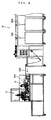
- an electric wire storage apparatus B is provided at the rear of the electric wire length measuring apparatus A, and a machining apparatus C is provided at the front of the electric wire length measuring apparatus A.
- the electric wire length measuring apparatus A exhibits a function of feeding, by a predetermined length, an electric wire 200 being drawn out of the electric wire storage apparatus B to the machining apparatus C located at the front thereof.
- the machining apparatus C is provided with machining devices, for example, a insulation displacement terminating machine, a crimping machine and a welder to perform, for example, connecting the electric wire 200 to a insulation displacement type connector by insulation displacement, crimping the electric wire 200 to a crimp-type contact, or welding the electric wire 200 to a contact.
- the electric wire 200 which is fed by the electric wire length measuring apparatus A to the machining apparatus C by a predetermined length is subjected to, for example, connecting to a insulation displacement type connector by insulation displacement, crimping to a crimp-type contact, wire cutting, or other fabrication to produce a wire harness.
- the electric wire storage apparatus B stores a necessary number of continuous electric wires 200 for producing a single wire harness, and the electric wires 200 are arranged to be drawn forward while keeping substantially parallel relationship in the width direction to each other when subjected to pulling forces.
- the electric wire 200 may be plural or singular.
- the method of storing the electric wire 200 is not limited, but for example, it may be rolled.
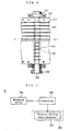
- the electric wire length measuring apparatus A comprises an electric wire feeding apparatus 100, a measuring apparatus 300 for measuring a value relating to the rotation of a lower roller 121 or an upper roller 131, which will be described later, and a controller 400 for controlling the rotative driving of the lower roller 121 and the upper roller 131 to bring the output of the measuring apparatus 300 to a predetermined value.
- the electric wire feeding apparatus 100 is provided with a lower roller 121, which is provided on the lower side of an electric wire path 111 extending in the front-rear direction to receive an electric wire and rotates around an axis extending in the width direction, and an upper roller 131, which is provided on the upper side of the electric wire path 111 and rotates around an axis extending in the width direction.
- the axis may be a real shaft or a virtual axis indicating the center of rotation.
- the electric wire feeding apparatus 100 is provided with a guide member 110, and this guide member 110 is provided with an electric wire path 111 extending in the front-rear direction, and a continuous electric wire 200 being drawn out of the electric wire storage apparatus B is so received in this electric wire path 111 that it can shift in the front-rear direction.
- the electric wire path 111 is a space that the electric wire 100 passes through.
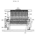
- the electric wire path 111 is provided for each electric wire 200, and when a plurality of electric wire paths 111 are provided, they are arranged, in the width direction, substantially in parallel to each other.
- the electric wire path 111 is formed by an internal space of a hole that penetrates through the guide member 110.
- the guide member may be provided with a groove opening upward, and the electric path 111 may be formed by an internal space of this groove. Strictly speaking, the electric wire path 111 is formed by a part of said internal space.
- the guide member 110 is provided with a lower side window 113, which opens the electric wire path 111 downward, and with an upper side window 112, which opens the electric wire path 111 upward, so that the lower roller 121 and the upper roller 131 can contact the electric wire 200 received in the electric wire path 111.
- the electric wire path 111 is formed by an internal space of a groove that is open upward, the path is provided with a lower side window only.
- the electric wire path may be formed by an internal space of the guide member, the electric wire path is not limited to an internal space of an entity; the electric wire path may be specified as a space extending in the front-rear direction near the electric wire feeding apparatus.
- the lower roller 121 is so provided on a lower shaft 122, which is provided on the lower side of the guide member 110 and extends in the width direction, that the lower roller 121 never shifts in relation to the lower shaft 122.
- the respective lower rollers 121 may be provided on the same lower shaft 122, or may be provided on different lower shafts.
- the upper roller 131 is so provided on an upper shaft 132, which is provided on the upper side of the guide member 110 and extends in the width direction, that the upper roller 131 never shifts in relation to the upper shaft 132.
- the respective upper rollers 131 may be provided on the same upper shaft 132, or may be provided on different upper shafts.
- the lower roller 121 and the upper roller 131 are provided with a groove for guiding the electric wire 200 by concaving the outer circumferential faces thereof in the radial direction so that the grooves prevent the electric wire 200 from shifting away in the width direction.
- the grooves are formed in U-letter shape or V-letter shape when seen in the front-rear direction.
- the grooves are provided with fine notches to prevent the electric wire 200 from slipping.
- the present invention includes an embodiment wherein the radii of the outer circumferential faces of the lower roller and the upper roller are constant in the width direction and no such groove is provided.
- the upper roller 131 and the lower roller 121 is energized toward the electric wire path 111, the upper roller 131 and the lower roller 121 are driven to rotate inversely to each other so that the peripheral velocities of the outer circumferences thereof are substantially the same, and the electric wire 200 being received in the electric wire path 111 is pressed by both the upper roller 131 and the lower roller 121 and fed forward (the feed direction of the electric wire is indicated by a single-line arrow in each diagram).
- the expression that the upper roller 131 and the lower roller 121 are driven to rotate inversely to each other means that the upper roller 131 and the lower roller 121 are rotatively driven so that they rotate in different rotational directions when seen in the axial direction.
- the reason for this arrangement is that as the upper roller 131 and the lower roller 121 are arranged on the upper side and the lower side of the electric wire path 111 to oppose each other, when they are driven to rotate inversely to each other, both rollers can exert forward-pushing forces to the electric wire 200.
- the upper roller 131 and the lower roller 121 contact the electric wire with their outer circumferential faces. Accordingly, the peripheral velocities of the outer circumferential faces of the upper roller 131 and the lower roller 121 will directly become the feed velocity of the electric wire 200.
- the electric wire feeding apparatus 100 is provided with an arm shaft 142 extending in the width direction.
- An intermediate part of an arm 141 is so provided on the arm shaft 142 that the intermediate part can rotate around the arm shaft 142, and an upper shaft 132 is so provided at one end of the arm 141 that the upper shaft can rotate.
- a plurality of arms 141 are provided according to the number of the electric wires 200, and each arm 141 is provided with the upper shaft 132.
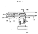
- the electric wire feeding apparatus 100 is so structured that the apparatus 100 is provided with an actuator 143, which expands or contracts, such as hydraulic or pneumatic cylinder, a telescopic actuating part thereof is connected to the other end of the arm 141, the arm 141 is made to swing by the operation of the actuator 143 and, in turn, the upper roller 131 is energized toward the electric wire path 111 to press the electric wire 200 in the electric wire path 111 (the movement of the upward double-line arrow of Fig. 2).
- an actuator 143 which expands or contracts, such as hydraulic or pneumatic cylinder, a telescopic actuating part thereof is connected to the other end of the arm 141, the arm 141 is made to swing by the operation of the actuator 143 and, in turn, the upper roller 131 is energized toward the electric wire path 111 to press the electric wire 200 in the electric wire path 111 (the movement of the upward double-line arrow of Fig. 2).
- the upper roller is energized toward the electric wire path 111.
- the upper roller may be so structured that the upper roller is enabled to shift substantially vertically, and the upper roller is energized toward the electric wire path 111 by means of an elastic member such as a spring.
- the lower roller is energized toward the electric wire path, or it may be so structured that both the upper roller and the lower roller are energized toward the electric wire path.
- the upper roller 131 and the lower roller 121 shifts upward or downward to move away from the electric wire path 111.
- the arm 141 will be swung and the upper roller 141 will shift upward to move away from the electric wire path 111 (the movement of the downward double-line arrow of Fig. 2).
- the upper roller 131 is designed to move away from the electric wire path 111.
- the upper roller is enabled to shift substantially vertically and the upper roller is shifted to move away from the electric wire path.
- the upper roller 131 is enabled to shift upward to move away from the electric wire path 111
- the lower roller is enabled to shift downward to move away from the electric wire path, or it may be so structured that both the upper roller and the lower roller are enabled to shift upward or downward to move away from the electric wire path.
- the upper roller and the lower roller are driven to rotate inversely to each other by a well-known rotative driving force generator such as a motor in such a way that the peripheral velocities of their outer circumferential faces are substantially the same.
- the upper roller and the lower roller may be driven to rotate by their respective dedicated rotative driving force generators, or both the rollers may be rotatively driven by a single common rotative driving force generator.
- a well-known power transmission device is provided between the upper/lower roller and the rotative driving force generator.
- the lower roller 121 and the upper roller 131 are rotatively driven by the rotative driving power generator 150 such as a single motor via a power transmission device 160 using belt or chain.
- the driving shaft of the rotative driving force generator 150 is provided with a driving pulley 161
- the lower shaft 122 is provided with a lower pulley 162 for driving the lower roller 121
- the arm shaft 142 is provided with an upper pulley 163 for driving the upper roller 131
- the electric wire feeding apparatus 100 is provided with an idler pulley 164 that rotates around a shaft extending in the width direction, and a first belt 167 is passed around these pulleys.
- the first belt 167 is so passed around that the inner circumferential face of the first belt 167 contacts the outer circumferential face of either one of the lower pulley 162 and the upper pulley 163 and the outer circumferential face of the first belt 167 contacts the outer circumferential face of the other pulley, and with this arrangement, the lower pulley 162 and the upper pulley 163 are rotatively driven inversely to each other when seen in the axial direction.
- the upper shaft may be directly driven by the upper pulley, however, in the case of the embodiment, as the upper shaft 132 is provided on the arm 141 that swings, the arm shaft 142 is rotatively driven by the upper pulley 163, and this rotation is transmitted to the upper shaft 132.
- the arm shaft 142 is provided with a fixed side pulley 165
- the upper shaft 132 is provided with a moving side pulley 166
- a second belt 168 is passed around the fixed side pulley 165 and the moving side pulley 166
- the rotation of the arm shaft 142 is transmitted to the moving side pulley 166 without altering the direction of rotation.
- the driving pulley 161, the lower pulley 162, the upper pulley 163, the idler pulley 164, the fixed side pulley 165, the moving side pulley 166, the first belt 167 and the second belt 168 constitute the power transmitting device 160 using belt or chain.
- the first belt and the second belt are toothed belts having teeth on both the inner circumferential face and the outer circumferential face from the viewpoint of accurately maintaining the rotational phase, however, any belt such as a flat belt may be used.
- any belt such as a flat belt may be used.
- chains may be used, and in that case, each pulley is replaced by a sprocket.
- it is a tension pulley that is provided in an intermediate part of the arm 141. This tension pulley is to adjust the tension in the second belt 168. It is provided as one thinks fit, when necessary.
- the measuring device 300 exhibits a function of measuring a value that relates to the rotation of the lower roller 121 or the upper roller 131.
- the value that relates to the rotation of the lower roller 121 or the upper roller 131 is a state quantity that is substantially proportional to the number of revolutions of the lower roller 121 or the upper roller 131.
- the measuring device 300 is a sensor such as an encoder, which detects the number of revolutions of the driving shaft of the rotative driving force generator 150.
- a sensor or the like which detects the number of revolutions of a rotating part of the rotative driving force generator 150 or the power transmission device 160, may be used.
- the controller 400 consists of, for example, an electric circuit and exhibits a function of receiving the output of the measuring device 300 and controlling the rotative driving of the lower roller 121 and the upper roller 131 so as to bring the output of the measuring device 300 to a predetermined value.
- the control of the rotative driving of the lower roller 121 and the upper roller 131 is given by signals outputted by the controller 400 to the rotative driving force generator 150. Through this control, the electric wire 200 can be fed by a predetermined length to the machining apparatus C.
- the number of revolutions of the rotative driving force generator 150 which is required to feed the electric wire 200 by a predetermined length, may be calculated, and the rotative driving force generator 150 may be controlled to rotate by only this number of revolutions.
- the control methods of the electric wire length measuring apparatus A having the electric wire feeding apparatus of the present invention are not limited to these methods.
- this electric wire feeding apparatus 100 when the electric wire 200 from the electric wire storage apparatus B is received in the electric wire path 111, the longitudinal direction of the electric wire 200 extending in the front-rear direction, the lower roller 121 and the upper roller 131 will contact the electric wire 200 with pressing forces, and when the upper roller 131 and the lower roller 121 are rotatively driven inversely to each other, the electric wire 200 will be fed to the forward machining apparatus C.
- the electric wire 200 hardly slips, it is possible to keep low the pressing forces of the upper roller 131 and the lower roller 121. Hence even when the electric wire 200 is thin, the electric wire 200 will not undergo deformation. As a result, the thickness range of electric wires 200 that can be fed will be extended as much as possible.
- the present invention includes an embodiment wherein at least one of the upper roller and the lower roller is energized toward the electric wire path while the upper roller and the lower roller are arranged to remain in the vicinity of the electric wire path.
- at least one of the upper roller 131 and the lower roller 121 is moved upward or downward to move away from the electric wire path 111.
- the feeding of the electric wire 200 can be stopped by suspending the operation of a specific upper roller 131 or lower roller 121.
- the present invention includes an embodiment wherein the lower roller and the upper roller are rotatively driven by a plurality of rotative driving force generators such as motors and an embodiment wherein no power transmission device intervenes.
- a plurality of rotative driving force generators such as motors
- no power transmission device intervenes it is so arranged that the lower roller 121 and the upper roller 131 are rotatively driven by a single rotative driving force generator 150 such as a motor via the power transmission device 160 using belt or chain.
- the lower roller 121 and the upper roller 131 can be rotatively driven by the single rotative driving force generator 150.
- the present invention is not limited by the embodiments described so far, and includes other embodiments that are substantially identical to them. Moreover, embodiments wherein various modifications described above are combined appropriately are included in the present embodiment.
Landscapes
- Engineering & Computer Science (AREA)
- Manufacturing & Machinery (AREA)
- Forwarding And Storing Of Filamentary Material (AREA)
- Filamentary Materials, Packages, And Safety Devices Therefor (AREA)
- Length Measuring Devices With Unspecified Measuring Means (AREA)
Applications Claiming Priority (2)
| Application Number | Priority Date | Filing Date | Title |
|---|---|---|---|
| JP2004093856A JP4494058B2 (ja) | 2004-03-26 | 2004-03-26 | 電線送り装置及びこれを備えた電線測長装置 |
| JP2004093856 | 2004-03-26 |
Publications (2)
| Publication Number | Publication Date |
|---|---|
| EP1580768A2 true EP1580768A2 (fr) | 2005-09-28 |
| EP1580768A3 EP1580768A3 (fr) | 2006-05-10 |
Family
ID=34858531
Family Applications (1)
| Application Number | Title | Priority Date | Filing Date |
|---|---|---|---|
| EP05251856A Withdrawn EP1580768A3 (fr) | 2004-03-26 | 2005-03-24 | Dispositif d'alimentation de fil électrique et dispositif de mesure de longueur de fils électriques le comprenant. |
Country Status (2)
| Country | Link |
|---|---|
| EP (1) | EP1580768A3 (fr) |
| JP (1) | JP4494058B2 (fr) |
Cited By (3)
| Publication number | Priority date | Publication date | Assignee | Title |
|---|---|---|---|---|
| US20110024402A1 (en) * | 2008-04-14 | 2011-02-03 | Kabushiki Kaisha Toshiba | Laser welding appratus and laser welding method |
| CN110986851A (zh) * | 2019-12-25 | 2020-04-10 | 昆山市富川机电科技有限公司 | 履带式计米器 |
| CN114906670A (zh) * | 2022-07-15 | 2022-08-16 | 江苏海强电缆有限公司 | 一种电缆计米盘绕架 |
Families Citing this family (1)
| Publication number | Priority date | Publication date | Assignee | Title |
|---|---|---|---|---|
| KR101998130B1 (ko) * | 2019-02-18 | 2019-07-09 | 강병우 | 이중호스 제작용 이동장치 |
Family Cites Families (7)
| Publication number | Priority date | Publication date | Assignee | Title |
|---|---|---|---|---|
| DE8418462U1 (de) * | 1984-09-20 | Hackner, Hans, 8431 Mühlhausen | Zieh- und Längenmeßgerät für elektrische Kabel | |
| CA1044575A (fr) * | 1976-02-23 | 1978-12-19 | Amp Incorporated | Dispositif et methode d'avance de fil metallique |
| US4043494A (en) * | 1976-02-23 | 1977-08-23 | Amp Incorporated | Apparatus for feeding a plurality of wires |
| JPH0245246Y2 (fr) * | 1986-01-17 | 1990-11-30 | ||
| DE3606059A1 (de) * | 1986-02-25 | 1987-08-27 | Fraunhofer Ges Forschung | Werkzeug zum verlegen und ablaengen von kabeln mit hilfe eines industrieroboters |
| JPH0930724A (ja) * | 1995-07-19 | 1997-02-04 | Hitachi Cable Ltd | 引取装置 |
| JPH10212068A (ja) * | 1996-11-28 | 1998-08-11 | Harness Sogo Gijutsu Kenkyusho:Kk | 複数種の電線加工設備における電線送り込み機構 |
-
2004
- 2004-03-26 JP JP2004093856A patent/JP4494058B2/ja not_active Expired - Fee Related
-
2005
- 2005-03-24 EP EP05251856A patent/EP1580768A3/fr not_active Withdrawn
Cited By (4)
| Publication number | Priority date | Publication date | Assignee | Title |
|---|---|---|---|---|
| US20110024402A1 (en) * | 2008-04-14 | 2011-02-03 | Kabushiki Kaisha Toshiba | Laser welding appratus and laser welding method |
| US8445810B2 (en) * | 2008-04-14 | 2013-05-21 | Kabushiki Kaisha Toshiba | Laser welding apparatus |
| CN110986851A (zh) * | 2019-12-25 | 2020-04-10 | 昆山市富川机电科技有限公司 | 履带式计米器 |
| CN114906670A (zh) * | 2022-07-15 | 2022-08-16 | 江苏海强电缆有限公司 | 一种电缆计米盘绕架 |
Also Published As
| Publication number | Publication date |
|---|---|
| JP4494058B2 (ja) | 2010-06-30 |
| JP2005280864A (ja) | 2005-10-13 |
| EP1580768A3 (fr) | 2006-05-10 |
Similar Documents
| Publication | Publication Date | Title |
|---|---|---|
| US10407261B2 (en) | Paper feeding apparatus | |
| US4665731A (en) | Bending apparatus | |
| EP1580768A2 (fr) | Dispositif d'alimentation de fil électrique et dispositif de mesure de longueur de fils électriques le comprenant | |
| US4354626A (en) | Apparatus for feeding a plurality of wires | |
| EP3057724A1 (fr) | Dispositif de formation de fil | |
| US4079611A (en) | Strip tension control system for the protection of fin tubing | |
| EP1998909B1 (fr) | Dispositif et procede de pliage d'une bande metallique | |
| EP0904864A2 (fr) | Machine à tréfiler à étages multiples avec système pour régler et ajuster la tension du fil | |
| AU778466B2 (en) | Device for producing metal fibers | |
| US5899373A (en) | Wire measuring apparatus | |
| EP0335986B1 (fr) | Dispositif d'entrainement de fil pour machines a decharge electrique a electrode-fil | |
| EP1245517B1 (fr) | Dispositif d'entraínement pour rouleau de papier | |
| EP0804979A1 (fr) | Dispositif de coupe pour une machine d'enroulement de ressorts hélicoidaux | |
| US864860A (en) | Wire-feeding device. | |
| CN224169237U (zh) | 一种长排铰生产线 | |
| EP0804978A1 (fr) | Machine d'enroulement de ressorts hélicoidaux à enroulement simple ou double | |
| JP2005268002A (ja) | 電線測長装置 | |
| JP4179966B2 (ja) | 用紙搬送部単独駆動方式の丁合機 | |
| CN223920240U (zh) | 一种滚轮摩擦输送装置 | |
| JP4080399B2 (ja) | 可動式電線送り装置 | |
| JP2004010302A (ja) | 段ボールシート製函機における給紙装置 | |
| CN104684399A (zh) | 用于将意大利面面皮供给到意大利面制作机中的设备 | |
| JP4375613B2 (ja) | 金型ロールへの心線巻き付け方法 | |
| US20120042707A1 (en) | Wire drawing device and method for manufacturing wire | |
| CN116081386A (zh) | 皮带送线装置 |
Legal Events
| Date | Code | Title | Description |
|---|---|---|---|
| PUAI | Public reference made under article 153(3) epc to a published international application that has entered the european phase |
Free format text: ORIGINAL CODE: 0009012 |
|
| AK | Designated contracting states |
Kind code of ref document: A2 Designated state(s): AT BE BG CH CY CZ DE DK EE ES FI FR GB GR HU IE IS IT LI LT LU MC NL PL PT RO SE SI SK TR |
|
| AX | Request for extension of the european patent |
Extension state: AL BA HR LV MK YU |
|
| PUAL | Search report despatched |
Free format text: ORIGINAL CODE: 0009013 |
|
| AK | Designated contracting states |
Kind code of ref document: A3 Designated state(s): AT BE BG CH CY CZ DE DK EE ES FI FR GB GR HU IE IS IT LI LT LU MC NL PL PT RO SE SI SK TR |
|
| AX | Request for extension of the european patent |
Extension state: AL BA HR LV MK YU |
|
| AKX | Designation fees paid | ||
| REG | Reference to a national code |
Ref country code: DE Ref legal event code: 8566 |
|
| STAA | Information on the status of an ep patent application or granted ep patent |
Free format text: STATUS: THE APPLICATION IS DEEMED TO BE WITHDRAWN |
|
| 18D | Application deemed to be withdrawn |
Effective date: 20061111 |