EP1580791B1 - Spectromètre de masse - Google Patents
Spectromètre de masse Download PDFInfo
- Publication number
- EP1580791B1 EP1580791B1 EP05005176.2A EP05005176A EP1580791B1 EP 1580791 B1 EP1580791 B1 EP 1580791B1 EP 05005176 A EP05005176 A EP 05005176A EP 1580791 B1 EP1580791 B1 EP 1580791B1
- Authority
- EP
- European Patent Office
- Prior art keywords
- chamber
- hole
- ion
- mass
- electric field
- Prior art date
- Legal status (The legal status is an assumption and is not a legal conclusion. Google has not performed a legal analysis and makes no representation as to the accuracy of the status listed.)
- Ceased
Links
- 150000002500 ions Chemical class 0.000 claims description 107
- 230000005684 electric field Effects 0.000 claims description 27
- 238000005086 pumping Methods 0.000 claims description 7
- 238000000034 method Methods 0.000 claims description 6
- 230000035945 sensitivity Effects 0.000 claims description 6
- 230000003287 optical effect Effects 0.000 description 15
- 239000007788 liquid Substances 0.000 description 11
- 239000000523 sample Substances 0.000 description 8
- 238000004458 analytical method Methods 0.000 description 3
- 238000001819 mass spectrum Methods 0.000 description 3
- 239000012488 sample solution Substances 0.000 description 3
- 238000007796 conventional method Methods 0.000 description 2
- 238000004895 liquid chromatography mass spectrometry Methods 0.000 description 2
- 238000012986 modification Methods 0.000 description 2
- 230000004048 modification Effects 0.000 description 2
- 239000002904 solvent Substances 0.000 description 2
- 101100031730 Arabidopsis thaliana PUMP1 gene Proteins 0.000 description 1
- 101100130645 Homo sapiens MMP7 gene Proteins 0.000 description 1
- 102100030417 Matrilysin Human genes 0.000 description 1
- 238000004364 calculation method Methods 0.000 description 1
- 230000009194 climbing Effects 0.000 description 1
- 238000005094 computer simulation Methods 0.000 description 1
- 238000010276 construction Methods 0.000 description 1
- 230000007423 decrease Effects 0.000 description 1
- 230000001419 dependent effect Effects 0.000 description 1
- 238000001514 detection method Methods 0.000 description 1
- 238000010586 diagram Methods 0.000 description 1
- 230000000694 effects Effects 0.000 description 1
- 230000008020 evaporation Effects 0.000 description 1
- 238000001704 evaporation Methods 0.000 description 1
- 238000002474 experimental method Methods 0.000 description 1
- 238000004949 mass spectrometry Methods 0.000 description 1
- 239000000203 mixture Substances 0.000 description 1
- 239000011435 rock Substances 0.000 description 1
- 239000007921 spray Substances 0.000 description 1
- 239000000126 substance Substances 0.000 description 1
Images


Classifications
-
- H—ELECTRICITY
- H01—ELECTRIC ELEMENTS
- H01J—ELECTRIC DISCHARGE TUBES OR DISCHARGE LAMPS
- H01J49/00—Particle spectrometers or separator tubes
- H01J49/02—Details
- H01J49/06—Electron- or ion-optical arrangements
- H01J49/067—Ion lenses, apertures, skimmers
Definitions
- the present invention relates to a mass spectrometer, specifically to one that has a differential pumping system, such as an atmospheric pressure ionizing mass spectrometer.
- Mass spectrometers are often used in combination with a liquid chromatograph or a gas chromatograph.
- the mass spectrometer is used as the detector of the liquid chromatograph.
- a sample liquid containing components to be detected is made to flow through a liquid chromatograph column, where the components are separated with respect to time while the sample passes through the column.
- the liquid (eluate) flowing out of the column is ionized by an interface, and the ionized component atoms or molecules are introduced into the mass spectrometer where the ions are separated by their mass to charge ratios. Ions of the components thus separated in the mass spectrometer are detected by an ion detector.
- the eluate is normally ionized under the atmospheric pressure, so that the interfaces are generally called an atmospheric pressure ionizing (API) interface.
- API atmospheric pressure ionizing
- the electro-spray ionizing (ESI) interface and atmospheric pressure chemical ionizing (ACPI) interface are typical API interfaces.
- the ionizing chamber is kept at substantially atmospheric pressure, but the mass spectrometer section, which includes a mass filter such as a quadrupole mass filter and the ion detector, must be kept at a very low pressure (or in a very high vacuum). Since the pressure difference is so large, several (usually two) intermediate vacuum chambers are provided between the ionizing chamber and the MS section, and the pressures of the intermediate vacuum chambers are gradually changed in order to keep the mass spectrometer section at very low pressure.
- the Unexamined Japanese Patent Publication No. 2000-149865 (which has matured to Patent No. 3379485 ) describes one of such differential pumping systems.
- ions are passed from a chamber of a higher pressure to an adjoining chamber of a lower pressure through a small hole called an orifice.
- an orifice In order to keep the low pressure of the lower pressure chamber, it is preferable to prevent unnecessary gas molecules from passing through the orifice.
- the object component ions should pass through the orifice at as large an amount as possible in order to enhance the detecting sensitivity.
- an ion lens applied with a DC voltage an electrostatic lens
- the rear focal point of the ion lens is set at the orifice, so that object ions are converged and effectively injected into the orifice.
- the conventional ion lens has the following drawback.
- a considerable amount of gas residual gas
- residual gas residual gas
- the ion is deflected and is difficult to converge again to the orifice with the electric field by the ion lens alone.
- the concentration of the ions at the converging point (or near the rear focal point) of the ion lens is very large, the ions are highly probable to collide with the residual gas molecules, and to be prevented from entering the orifice and going to the subsequent chamber. This deteriorates the sensitivity of the sample analysis.
- a further conventional mass spectrometer comprising a voltage generator for applying a RF voltage to an ion lens is disclosed in US 2003/0222213 A1 .
- an object of the present invention is to improve the sensitivity of a mass spectrometer using an API interface by making more ions pass the intermediate vacuum chambers while preventing unnecessary residual gas molecules from doing the same.
- a mass spectrometer adopting a differential pumping system according to an aspect includes:
- One method is to use the wall (in which the hole is formed) between two adjoining chambers (i.e., between the ionization chamber and the first intermediate vacuum chamber, between two intermediate vacuum chambers, or between the last intermediate chamber and the mass analyzing chamber) as an electrode, and apply an AC voltage to the wall.
- the walls between chambers are often required to be electrically grounded (to 0V) for some other reason. Therefore another method is recommended in which an independent electrode having an aperture near the hole is provided, and the AC voltage is applied to the electrode.
- the electrode may be placed on the higher pressure chamber side or the lower pressure chamber side, but the higher pressure chamber side is preferable for the following reason.
- the hole is preferably conically shaped with the larger end on the higher pressure chamber side, and the smaller end on the lower pressure chamber side.
- the electrode is better placed on the higher pressure chamber side in order to generate the AC electric field in the space within the conical hole, so that the ions can be adequately confined to the hole.
- a deflected ion can be pulled back toward the hole owing to the AC electric field generated near the hole. This improves the ion passing efficiency through the hole, and increases the number of ions reaching the mass filter and ion detector, which of course enhances the sensitivity of the mass analysis.
- FIG. 1 A mass spectrometer using an ESI interface embodying the present invention is described using the accompanying drawings.
- a liquid chromatograph is attached to the mass spectrometer, wherein the exit of the column of the liquid chromatograph is connected to the nozzle 2 of the ionizing chamber 1.
- a first intermediate vacuum chamber 4 and a second intermediate vacuum chamber 8 are provided between the ionizing chamber 1 and a mass analyzing chamber 10 in which a quadrupole mass filter 11 and an ion detector 12 are accommodated.
- the chambers 1, 4, 8 and 10 are separated by respective walls, wherein the wall between the ionizing chamber 1 and the first intermediate vacuum chamber 4 is equipped with a dissolvation line 3, and the wall 7 between the first intermediate vacuum chamber 4 and the second intermediate vacuum chamber 8 has an orifice 70.
- the inner diameters of both the dissolvation line 3 and the orifice 70 are rendered very small.
- the pressure in the ionizing chamber 1, which functions as the ion source, is almost atmospheric (i.e., at about 10 5 Pa), because the liquid sample solution constantly flows from the column of the liquid chromatograph into the ionizing chamber 1 through the nozzle 2 and is vaporized.
- the pressure in the first intermediate vacuum chamber 4 is kept at about 10 2 Pa with a rotary pump (PUMP1 in Fig. 1 ), and that in the second intermediate vacuum chamber 8 is kept at about 10 -1 to 10 -2 Pa with a turbo molecular pump (PUMP2).
- the mass analyzing chamber 10 is evacuated by another turbo molecular pump (PUMP3) up to such a low pressure of 10 -3 to 10 -4 Pa.
- PUMP3 turbo molecular pump
- the sample solution is electro-sprayed by the nozzle 2, to which is applied a high voltage, into the ionizing chamber 1, so that the droplets of the sample solution are given electric charges when sprayed.
- the sample molecules are ionized, though not completely.
- the mixture of the ionized sample molecules and unionized tiny droplets is drawn into the dissolvation line 3 owing to the pressure difference between the ionizing chamber 1 and the first intermediate vacuum chamber 4, where the ionization of the sample is promoted because the solvent in the droplets is heated and evaporates out.
- a first ion lens 5 is provided in the first intermediate vacuum chamber 4, which assists the introduction of the ions from the ionizing chamber 1 through the dissolvation line 3, and converges the ions to the orifice 70.
- the first ion lens 5 is composed of three rows of electrode units having gradually narrowing apertures aligned along the ion optical axis C, where each electrode unit is composed of four plate electrodes surrounding the ion optical axis C.
- an auxiliary electrode 6 having a large aperture is provided near the wall 7 to form an AC electric field for confining ions near the orifice 70.
- the AC electric field will be discussed later.
- the ions passing through the orifice 70 and entering the second vacuum chamber 8 are converged by a second ion lens 9 and sent to the mass analyzing chamber 10.
- the second ion lens 9 is an octapole type which has eight rod electrodes arranged in parallel and symmetrically around the ion optical axis C.
- only ions having a specific mass to charge ratio can pass through the longitudinal space of the mass filter 11 along the ion optical axis C, while other ions dissipate.
- the ions passing through the mass filter 11 reach the ion detector 12, which generates a signal corresponding to the number of ions detected.
- auxiliary electrode 6 To the auxiliary electrode 6 is applied an AC voltage of a predetermined amplitude and predetermined frequency by an ion-confining voltage generator 13, whereby an AC electric field is generated in the space around the aperture of the auxiliary electrode 6.
- the orifice 70 is conically shaped, as shown in (a) of Fig. 2 , with the larger end on the side of the first intermediate vacuum chamber 4.
- the AC electric field generated by the auxiliary electrode 6 placed on the same side easily intrudes into the space 72 surrounded by the conical wall 71 of the orifice 70. Owing to the AC electric field formed in the conical space 72, an electric pseudo-potential is generated there, whose cross-sectional contour around the ion optical axis C is shown in (b) of Fig. 2 .
- the contour of the pseudo-potential shown in (b) of Fig. 2 looks as if a pseudo-potential pocket is formed around the ion optical axis C.
- an ion cannot rest at a higher potential and tends to move toward a lower potential.
- the ion reaches the lowest potential point, it overruns the point due to its kinetic momentum and climbs the pseudo-potential to a higher position.
- the ion loses its kinetic energy in climbing the pseudo-potential slope, it then falls toward the lowest point.
- ions rock around the ion optical axis C and gradually gather there.
- the force for confining an ion to the path (and to the orifice 70) depends on the frequency and amplitude of the AC voltage, and the mass to charge ratio of the ion. Therefore it is preferable to adjust either the frequency or the amplitude of the AC voltage according to the mass to charge ratio of an object ion to be analyzed. Generally, adjusting the amplitude is easier than adjusting the frequency. If the mass filter is a quadrupole mass filter, as in the present embodiment, the amplitude of the DC voltage and the AC voltage applied to the quadrupole mass filter is scanned according to the mass to charge ratio of the object ion.
- the ion-confining voltage generator 13 scans the amplitude of the AC voltage applied to the auxiliary electrode 6 corresponding to the scan of the voltage to the quadrupole mass filter 11.
- the optimal combination of the frequency and amplitude of the AC voltage can be determined beforehand with experiments or calculations.
- a computer simulation is made to figure out the trajectory of ions around the orifice 70.
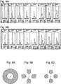
- the results are shown in Figs. 3A and 3B , where Fig. 3A is the result of applying an appropriate AC voltage to the auxiliary electrode 6, and Fig. 3B is the result of applying no voltage.
- Fig. 3B a large portion of the ions coming to the orifice 70 collide with the wall 7 and with the conical wall 71 around the orifice 70.
- the ions are confined near the ion optical axis C, and most ions pass through the orifice 70.
- Figs. 4A and 4B correspond to the cases of Figs. 3A and 3B respectively.
- Both Figs. 4A and 4B show mass spectra of several ions of different mass to charge ratios, where their values are, from left to right, 168.10, 256.15, 344.20, 520.35, 740.45, 872.55, 1048.65 and 1268.75. Since the scale of the ordinate of the graphs of Figs. 4A and 4B is the same, the height of the peaks can be compared as they are.
- the ion detection signal is larger in the case of the present invention ( Fig. 4A ) at all mass to charge ratios tested. This proves that the present invention is effective in improving the sensitivity of a mass analysis, and makes it possible to analyze a tiny amount of sample.
- the auxiliary electrode 6 is provided in the first intermediate vacuum chamber 4 in the above embodiment.
- the auxiliary electrode 6 may be placed in the second intermediate vacuum chamber 8.
- the wall 7 between the two intermediate vacuum chambers 4 and 8 can be used to form the above described confining electric field.
- the wall 7 is generally electrically grounded in actual mass spectrometers. Therefore it is preferable to provide an auxiliary electrode 6 separately from the wall 7.
- auxiliary electrode 6 it is further preferable to place the auxiliary electrode 6 just before the wall 7, and shape the orifice 70 conical as shown in Fig. 2 in order to form an adequate AC electric field in the space 72 of the orifice 70.
- the auxiliary electrode 6 can be shaped other than as a ring as described above and shown in Fig. 5A , but it may be formed by separate plates or discs as shown in Fig. 5B or 5C .
Landscapes
- Chemical & Material Sciences (AREA)
- Analytical Chemistry (AREA)
- Other Investigation Or Analysis Of Materials By Electrical Means (AREA)
- Electron Tubes For Measurement (AREA)
Claims (6)
- Spectromètre de masse qui adopte un système de pompage différentiel comprenant :une chambre d'ionisation (1) sensiblement à pression atmosphérique ;une chambre d'analyse de masse (10) basse pression ;une ou plusieurs chambre(s) à vide intermédiaire(s) (4, 8) qui est/sont prévue(s) entre la chambre d'ionisation (1) et la chambre d'analyse de masse (10), dont toutes forment une série de chambres selon un ordre qui va de la pression plus élevée à la pression plus basse ;un trou (70) qui est prévu entre des chambres contiguës pour permettre que des ions qui sont destinés à être analysés en termes de masse passent au travers ; etune lentille ionique (5, 9) dans les une ou plusieurs chambres sous vide intermédiaires (4, 8) ;caractérisé en ce que le spectromètre de masse comprend en outre :
un générateur de champ électrique alternatif (6, 13) pour générer un champ électrique alternatif dans l'espace autour du trou (70) pour confiner un ion sur le trou (70) ; dans lequel :le générateur de champ électrique alternatif (6, 13) est une combinaison d'une électrode (6) qui comporte une ouverture qui est placée à proximité du trou (70), entre le trou (70) et la lentille ionique (5, 9), et d'un générateur de tension (13) pour appliquer une tension alternative sur l'électrode (6) ;l'ouverture est placée sur un côté d'une chambre (4) de pression plus élevée ;le trou (70) est de forme conique avec un diamètre plus grand sur le côté de la chambre de pression plus élevée (4) ; etle spectromètre de masse est configuré de telle sorte que le champ électrique alternatif soit introduit à l'intérieur de l'espace (72) qui est entouré par une paroi conique (71) du trou (70). - Spectromètre de masse selon la revendication 1, dans lequel l'électrode (6) est prévue dans une chambre à vide intermédiaire (4) qui est contiguë à la chambre d'ionisation (1).
- Procédé d'amélioration d'une sensibilité d'un spectromètre de masse qui adopte un système de pompage différentiel et qui comprend :une chambre d'ionisation (1) sensiblement à pression atmosphérique ;une chambre d'analyse de masse (10) basse pression ;une ou plusieurs chambre(s) à vide intermédiaire(s) (4, 8) qui est/sont prévue(s) entre la chambre d'ionisation (1) et la chambre d'analyse de masse (10), dont toutes forment une série de chambres selon un ordre qui va de la pression plus élevée à la pression plus basse ;un trou (70) qui est prévu entre des chambres contiguës pour permettre que des ions qui sont destinés à être analysés en termes de masse passent au travers ; etune lentille ionique (5, 9) dans les une ou plusieurs chambres sous vide intermédiaires (4, 8) ;caractérisé en ce qu'un champ électrique alternatif est généré dans un espace à l'intérieur du trou (70) pour confiner des ions dans l'espace au moyen d'un générateur de champ électrique alternatif (6, 13) ; dans lequel :le générateur de champ électrique alternatif (6, 13) est une combinaison d'une électrode (6) qui comporte une ouverture qui est placée à proximité du trou (70), entre le trou (70) et la lentille ionique (5, 9), et d'un générateur de tension (13) pour appliquer une tension alternative sur l'électrode (6) ;l'ouverture est placée sur un côté d'une chambre (4) de pression plus élevée ;le trou (70) est de forme conique avec un diamètre plus grand sur le côté de la chambre de pression plus élevée (4) ; etle spectromètre de masse est configuré de telle sorte que le champ électrique alternatif soit introduit à l'intérieur de l'espace (72) qui est entouré par une paroi conique (71) du trou (70).
- Procédé selon la revendication 3, dans lequel l'électrode (6) est prévue dans une chambre sous vide intermédiaire qui est contiguë à la chambre d'ionisation (1).
- Procédé selon la revendication 3, dans lequel une fréquence et une amplitude de la tension alternative sont déterminées conformément à un rapport masse sur charge d'un ion qui est destiné à être analysé.
- Procédé selon la revendication 5, dans lequel l'amplitude et la fréquence de la tension alternative sont déterminées de telle sorte qu'un champ électrique alternatif qui est généré dans le trou (70) satisfasse la formule qui suit :

Applications Claiming Priority (2)
| Application Number | Priority Date | Filing Date | Title |
|---|---|---|---|
| JP2004068365A JP4193734B2 (ja) | 2004-03-11 | 2004-03-11 | 質量分析装置 |
| JP2004068365 | 2004-03-11 |
Publications (3)
| Publication Number | Publication Date |
|---|---|
| EP1580791A2 EP1580791A2 (fr) | 2005-09-28 |
| EP1580791A3 EP1580791A3 (fr) | 2006-10-25 |
| EP1580791B1 true EP1580791B1 (fr) | 2018-08-15 |
Family
ID=34858333
Family Applications (1)
| Application Number | Title | Priority Date | Filing Date |
|---|---|---|---|
| EP05005176.2A Ceased EP1580791B1 (fr) | 2004-03-11 | 2005-03-09 | Spectromètre de masse |
Country Status (3)
| Country | Link |
|---|---|
| US (1) | US7230237B2 (fr) |
| EP (1) | EP1580791B1 (fr) |
| JP (1) | JP4193734B2 (fr) |
Families Citing this family (18)
| Publication number | Priority date | Publication date | Assignee | Title |
|---|---|---|---|---|
| US8890058B2 (en) * | 2005-11-16 | 2014-11-18 | Shimadzu Corporation | Mass spectrometer |
| EP2013895B8 (fr) * | 2006-04-28 | 2019-07-17 | Micromass UK Limited | Spectrometre de masse |
| GB0608470D0 (en) | 2006-04-28 | 2006-06-07 | Micromass Ltd | Mass spectrometer |
| US20090283674A1 (en) | 2006-11-07 | 2009-11-19 | Reinhold Pesch | Efficient Atmospheric Pressure Interface for Mass Spectrometers and Method |
| JP4816426B2 (ja) * | 2006-11-22 | 2011-11-16 | 株式会社島津製作所 | 質量分析計 |
| CN101675496B (zh) * | 2007-05-21 | 2013-01-02 | 株式会社岛津制作所 | 带电粒子凝聚装置 |
| FI123930B (fi) * | 2008-04-03 | 2013-12-31 | Environics Oy | Menetelmä kaasujen mittaamiseksi |
| JP5135073B2 (ja) * | 2008-06-18 | 2013-01-30 | 出光興産株式会社 | 有機薄膜トランジスタ |
| US7915580B2 (en) * | 2008-10-15 | 2011-03-29 | Thermo Finnigan Llc | Electro-dynamic or electro-static lens coupled to a stacked ring ion guide |
| WO2011131142A1 (fr) * | 2010-04-22 | 2011-10-27 | 岛津分析技术研发(上海)有限公司 | Procédé et appareil pour générer et analyser des ions |
| CN102221576B (zh) | 2010-04-15 | 2015-09-16 | 岛津分析技术研发(上海)有限公司 | 一种产生、分析离子的方法与装置 |
| JP2012009290A (ja) | 2010-06-25 | 2012-01-12 | Hitachi High-Technologies Corp | 質量分析装置 |
| GB2488429B (en) * | 2011-02-28 | 2016-09-28 | Agilent Technologies Inc | Ion slicer with acceleration and deceleration optics |
| TWI539154B (zh) | 2012-12-19 | 2016-06-21 | 英福康公司 | 雙重偵測殘餘氣體分析器 |
| US10229823B2 (en) * | 2015-08-06 | 2019-03-12 | Shimadzu Corporation | Mass spectrometer |
| WO2020129199A1 (fr) * | 2018-12-19 | 2020-06-25 | 株式会社島津製作所 | Spectromètre de masse |
| US11658020B2 (en) | 2020-11-24 | 2023-05-23 | Inficon, Inc. | Ion source assembly with multiple ionization volumes for use in a mass spectrometer |
| US20240153753A1 (en) * | 2022-11-07 | 2024-05-09 | Inficon Inc. | Atmospheric pressure ionization coupled to an electron ionization mass spectrometer |
Citations (1)
| Publication number | Priority date | Publication date | Assignee | Title |
|---|---|---|---|---|
| JP2000149865A (ja) * | 1998-09-02 | 2000-05-30 | Shimadzu Corp | 質量分析装置 |
Family Cites Families (9)
| Publication number | Priority date | Publication date | Assignee | Title |
|---|---|---|---|---|
| US6002130A (en) * | 1991-09-12 | 1999-12-14 | Hitachi, Ltd. | Mass spectrometry and mass spectrometer |
| AU1932095A (en) * | 1994-02-28 | 1995-09-11 | Analytica Of Branford, Inc. | Multipole ion guide for mass spectrometry |
| GB9612070D0 (en) * | 1996-06-10 | 1996-08-14 | Micromass Ltd | Plasma mass spectrometer |
| JP4350242B2 (ja) * | 1999-11-29 | 2009-10-21 | パナソニック株式会社 | 超音波振動発生装置及び方法、並びにバンプ接合装置 |
| US6788066B2 (en) * | 2000-01-19 | 2004-09-07 | Baker Hughes Incorporated | Method and apparatus for measuring resistivity and dielectric in a well core in a measurement while drilling tool |
| US6646258B2 (en) * | 2001-01-22 | 2003-11-11 | Agilent Technologies, Inc. | Concave electrode ion pipe |
| JP2004014177A (ja) | 2002-06-04 | 2004-01-15 | Shimadzu Corp | 質量分析装置 |
| US7064319B2 (en) * | 2003-03-31 | 2006-06-20 | Hitachi High-Technologies Corporation | Mass spectrometer |
| CA2431603C (fr) * | 2003-06-10 | 2012-03-27 | Micromass Uk Limited | Spectrometre de masse |
-
2004
- 2004-03-11 JP JP2004068365A patent/JP4193734B2/ja not_active Expired - Fee Related
-
2005
- 2005-03-09 EP EP05005176.2A patent/EP1580791B1/fr not_active Ceased
- 2005-03-10 US US11/075,719 patent/US7230237B2/en not_active Expired - Fee Related
Patent Citations (1)
| Publication number | Priority date | Publication date | Assignee | Title |
|---|---|---|---|---|
| JP2000149865A (ja) * | 1998-09-02 | 2000-05-30 | Shimadzu Corp | 質量分析装置 |
Also Published As
| Publication number | Publication date |
|---|---|
| US7230237B2 (en) | 2007-06-12 |
| EP1580791A3 (fr) | 2006-10-25 |
| EP1580791A2 (fr) | 2005-09-28 |
| JP4193734B2 (ja) | 2008-12-10 |
| JP2005259483A (ja) | 2005-09-22 |
| US20050199803A1 (en) | 2005-09-15 |
Similar Documents
| Publication | Publication Date | Title |
|---|---|---|
| EP1580791B1 (fr) | Spectromètre de masse | |
| EP3577677B1 (fr) | Spectromètre de masse à transformée de fourier | |
| US20120056085A1 (en) | Ion analysis apparatus and method of use | |
| US8822915B2 (en) | Atmospheric pressure ionization mass spectrometer | |
| US20030034451A1 (en) | Multipole ion guide for mass spectrometry | |
| US9916971B2 (en) | Systems and methods of suppressing unwanted ions | |
| US12230489B2 (en) | High pressure mass analyzer | |
| US6646255B2 (en) | Liquid chromatograph/mass spectrometer and its ionization interface | |
| US7145136B2 (en) | Atmospheric pressure ionization with optimized drying gas flow | |
| US11152202B2 (en) | Time-of-flight mass spectrometer | |
| US6075243A (en) | Mass spectrometer | |
| US20250140544A1 (en) | Mass spectrometer ion source | |
| JP3052929B2 (ja) | 質量分析装置 | |
| JP7117371B2 (ja) | ガス混合物を使用してイオンを選択するシステムおよび方法 | |
| US20240162027A1 (en) | System and Method for Variable FFT Analysis Windows in Mass Spectrometry | |
| US12456615B2 (en) | Identification of harmonics in RF quadrupole Fourier transform mass spectra | |
| Bruins | ESI source design | |
| US20230290630A1 (en) | Signal-to-Noise Improvement in Fourier Transform Quadrupole Mass Spectrometer | |
| Heintz | Comprehensive characterization of deeply penetrating charged droplet signatures in the high-vacuum region of electrospray ionization mass spectrometry |
Legal Events
| Date | Code | Title | Description |
|---|---|---|---|
| PUAI | Public reference made under article 153(3) epc to a published international application that has entered the european phase |
Free format text: ORIGINAL CODE: 0009012 |
|
| AK | Designated contracting states |
Kind code of ref document: A2 Designated state(s): AT BE BG CH CY CZ DE DK EE ES FI FR GB GR HU IE IS IT LI LT LU MC NL PL PT RO SE SI SK TR |
|
| AX | Request for extension of the european patent |
Extension state: AL BA HR LV MK YU |
|
| PUAL | Search report despatched |
Free format text: ORIGINAL CODE: 0009013 |
|
| AK | Designated contracting states |
Kind code of ref document: A3 Designated state(s): AT BE BG CH CY CZ DE DK EE ES FI FR GB GR HU IE IS IT LI LT LU MC NL PL PT RO SE SI SK TR |
|
| AX | Request for extension of the european patent |
Extension state: AL BA HR LV MK YU |
|
| 17P | Request for examination filed |
Effective date: 20061222 |
|
| AKX | Designation fees paid |
Designated state(s): DE GB |
|
| 17Q | First examination report despatched |
Effective date: 20111222 |
|
| REG | Reference to a national code |
Ref country code: DE Ref legal event code: R079 Ref document number: 602005054410 Country of ref document: DE Free format text: PREVIOUS MAIN CLASS: H01J0049040000 Ipc: H01J0049060000 |
|
| GRAP | Despatch of communication of intention to grant a patent |
Free format text: ORIGINAL CODE: EPIDOSNIGR1 |
|
| STAA | Information on the status of an ep patent application or granted ep patent |
Free format text: STATUS: GRANT OF PATENT IS INTENDED |
|
| RIC1 | Information provided on ipc code assigned before grant |
Ipc: H01J 49/06 20060101AFI20180201BHEP |
|
| INTG | Intention to grant announced |
Effective date: 20180222 |
|
| GRAS | Grant fee paid |
Free format text: ORIGINAL CODE: EPIDOSNIGR3 |
|
| GRAA | (expected) grant |
Free format text: ORIGINAL CODE: 0009210 |
|
| STAA | Information on the status of an ep patent application or granted ep patent |
Free format text: STATUS: THE PATENT HAS BEEN GRANTED |
|
| AK | Designated contracting states |
Kind code of ref document: B1 Designated state(s): DE GB |
|
| REG | Reference to a national code |
Ref country code: GB Ref legal event code: FG4D |
|
| REG | Reference to a national code |
Ref country code: DE Ref legal event code: R096 Ref document number: 602005054410 Country of ref document: DE |
|
| REG | Reference to a national code |
Ref country code: DE Ref legal event code: R097 Ref document number: 602005054410 Country of ref document: DE |
|
| PLBE | No opposition filed within time limit |
Free format text: ORIGINAL CODE: 0009261 |
|
| STAA | Information on the status of an ep patent application or granted ep patent |
Free format text: STATUS: NO OPPOSITION FILED WITHIN TIME LIMIT |
|
| 26N | No opposition filed |
Effective date: 20190516 |
|
| REG | Reference to a national code |
Ref country code: DE Ref legal event code: R119 Ref document number: 602005054410 Country of ref document: DE |
|
| GBPC | Gb: european patent ceased through non-payment of renewal fee |
Effective date: 20190309 |
|
| PG25 | Lapsed in a contracting state [announced via postgrant information from national office to epo] |
Ref country code: GB Free format text: LAPSE BECAUSE OF NON-PAYMENT OF DUE FEES Effective date: 20190309 Ref country code: DE Free format text: LAPSE BECAUSE OF NON-PAYMENT OF DUE FEES Effective date: 20191001 |