EP1580793A2 - Verfahren und Gerät zur Auswahl von Einlässen eines FAIMS mit mehreren Einlässen - Google Patents
Verfahren und Gerät zur Auswahl von Einlässen eines FAIMS mit mehreren Einlässen Download PDFInfo
- Publication number
- EP1580793A2 EP1580793A2 EP05405218A EP05405218A EP1580793A2 EP 1580793 A2 EP1580793 A2 EP 1580793A2 EP 05405218 A EP05405218 A EP 05405218A EP 05405218 A EP05405218 A EP 05405218A EP 1580793 A2 EP1580793 A2 EP 1580793A2
- Authority
- EP
- European Patent Office
- Prior art keywords
- ions
- ion
- electrode
- inlet orifice
- ion inlet
- Prior art date
- Legal status (The legal status is an assumption and is not a legal conclusion. Google has not performed a legal analysis and makes no representation as to the accuracy of the status listed.)
- Withdrawn
Links
- 238000000766 differential mobility spectroscopy Methods 0.000 title claims description 129
- 238000000034 method Methods 0.000 title claims description 18
- 150000002500 ions Chemical class 0.000 claims abstract description 407
- 239000000203 mixture Substances 0.000 claims description 33
- 238000000926 separation method Methods 0.000 claims description 21
- 239000000523 sample Substances 0.000 claims description 17
- 238000004891 communication Methods 0.000 claims description 16
- 150000001875 compounds Chemical class 0.000 claims description 14
- 230000005540 biological transmission Effects 0.000 claims description 7
- 239000002243 precursor Substances 0.000 claims description 7
- 230000000694 effects Effects 0.000 claims description 6
- 239000012530 fluid Substances 0.000 claims description 6
- 230000005684 electric field Effects 0.000 claims description 5
- 239000012491 analyte Substances 0.000 claims 1
- 230000007246 mechanism Effects 0.000 abstract description 3
- 239000007789 gas Substances 0.000 description 25
- 238000000132 electrospray ionisation Methods 0.000 description 10
- 238000010586 diagram Methods 0.000 description 9
- 238000004128 high performance liquid chromatography Methods 0.000 description 7
- 238000004949 mass spectrometry Methods 0.000 description 6
- 230000009471 action Effects 0.000 description 4
- 238000010828 elution Methods 0.000 description 4
- 239000012159 carrier gas Substances 0.000 description 3
- 239000012777 electrically insulating material Substances 0.000 description 3
- 238000005259 measurement Methods 0.000 description 3
- 238000004458 analytical method Methods 0.000 description 2
- 238000013459 approach Methods 0.000 description 2
- 230000008901 benefit Effects 0.000 description 2
- 239000004020 conductor Substances 0.000 description 2
- 238000001514 detection method Methods 0.000 description 2
- 239000012212 insulator Substances 0.000 description 2
- 238000012163 sequencing technique Methods 0.000 description 2
- 238000005507 spraying Methods 0.000 description 2
- 230000032258 transport Effects 0.000 description 2
- 239000004696 Poly ether ether ketone Substances 0.000 description 1
- 239000000654 additive Substances 0.000 description 1
- 230000000996 additive effect Effects 0.000 description 1
- 238000000065 atmospheric pressure chemical ionisation Methods 0.000 description 1
- 230000004888 barrier function Effects 0.000 description 1
- JUPQTSLXMOCDHR-UHFFFAOYSA-N benzene-1,4-diol;bis(4-fluorophenyl)methanone Chemical compound OC1=CC=C(O)C=C1.C1=CC(F)=CC=C1C(=O)C1=CC=C(F)C=C1 JUPQTSLXMOCDHR-UHFFFAOYSA-N 0.000 description 1
- 230000015572 biosynthetic process Effects 0.000 description 1
- 230000000903 blocking effect Effects 0.000 description 1
- 230000008859 change Effects 0.000 description 1
- 230000001419 dependent effect Effects 0.000 description 1
- 238000005516 engineering process Methods 0.000 description 1
- 239000011888 foil Substances 0.000 description 1
- 239000011810 insulating material Substances 0.000 description 1
- 238000002955 isolation Methods 0.000 description 1
- 239000007788 liquid Substances 0.000 description 1
- 238000004519 manufacturing process Methods 0.000 description 1
- 238000000816 matrix-assisted laser desorption--ionisation Methods 0.000 description 1
- 238000012986 modification Methods 0.000 description 1
- 230000004048 modification Effects 0.000 description 1
- 230000037361 pathway Effects 0.000 description 1
- 229920002530 polyetherether ketone Polymers 0.000 description 1
- 230000004044 response Effects 0.000 description 1
- 230000000717 retained effect Effects 0.000 description 1
- 230000035945 sensitivity Effects 0.000 description 1
- 239000007921 spray Substances 0.000 description 1
- 239000000126 substance Substances 0.000 description 1
- 239000003643 water by type Substances 0.000 description 1
Images








Classifications
-
- G—PHYSICS
- G01—MEASURING; TESTING
- G01N—INVESTIGATING OR ANALYSING MATERIALS BY DETERMINING THEIR CHEMICAL OR PHYSICAL PROPERTIES
- G01N27/00—Investigating or analysing materials by the use of electric, electrochemical, or magnetic means
- G01N27/62—Investigating or analysing materials by the use of electric, electrochemical, or magnetic means by investigating the ionisation of gases, e.g. aerosols; by investigating electric discharges, e.g. emission of cathode
- G01N27/622—Ion mobility spectrometry
- G01N27/624—Differential mobility spectrometry [DMS]; Field asymmetric-waveform ion mobility spectrometry [FAIMS]
-
- H—ELECTRICITY
- H01—ELECTRIC ELEMENTS
- H01J—ELECTRIC DISCHARGE TUBES OR DISCHARGE LAMPS
- H01J49/00—Particle spectrometers or separator tubes
- H01J49/02—Details
- H01J49/06—Electron- or ion-optical arrangements
- H01J49/067—Ion lenses, apertures, skimmers
Definitions
- This invention relates generally to High-Field Asymmetric Waveform Ion Mobility Spectrometry (FAIMS) and more particularly to a selection system for multiple inlet FAIMS.
- FAIMS High-Field Asymmetric Waveform Ion Mobility Spectrometry
- an ionization source such as for example electrospray ionization (ESI)
- an atmospheric pressure gas phase ion separator such as for example a high-field asymmetric waveform ion mobility spectrometer (FAIMS)
- a detection system such as for example mass spectrometry (MS)
- ESI electrospray ionization
- FIMS atmospheric pressure gas phase ion separator
- MS mass spectrometry
- ions optionally are introduced via multiple inlets.
- a version of FAIMS with openings around the circumference of the outer electrode have been described previously, such as for instance in United States Patent 6,753,522 which issued on June 22, 2004 in the name of Guevremont et al.
- the ions originating from one of a plurality of ESI sources are selected by moving a ring version of the curtain plate around the FAIMS such that a single opening in the ring is situated in front of each opening in turn.
- the ring-shaped electrode is mechanically very difficult and inconvenient to actuate in an automated manner.
- the ring-shaped electrode does not readily support introduction of ions from different ionization sources via inlet orifices that are disposed at different positions along the length of the FAIMS analyzer.
- an apparatus for separating ions comprising: a first electrode; a second electrode disposed in a spaced-apart relationship with the first electrode, a space between the first electrode and the second electrode defining a FAIMS analyzer region therebetween, the FAIMS analyzer region in fluid communication with an ion outlet orifice; a first ion inlet orifice defined within a first portion of the first electrode such that ions introduced via the first ion inlet orifice travel a first distance between the first ion inlet orifice and the ion outlet orifice; a second ion inlet orifice defined within a second portion of the first electrode such that ions introduced via the second ion inlet orifice travel a second distance between the second ion inlet orifice and the ion outlet orifice, the second distance being shorter than the first distance; and, an ion inlet orifice selector comprising a selector electrode having an opening defined therethrough, the
- a method for separating ions comprising: providing a FAIMS analyzer region in fluid communication with an ion detector; providing a first ionization source in communication with a sample material including a precursor of an ion type of interest; providing a second ionization source in communication with a sample material including the precursor of the ion type of interest; using the first ionization source, producing a mixture of ions comprising different types of ions including the ion type of interest; during a first period of time, directing the ions from the first ionization source along a path of a first length through the FAIMS analyzer region, the first length being sufficient to effect at least a partial separation of the ion type of interest from other types of ions in the mixture; using the ion detector, detecting ions after the ions have traveled the first length; using the second ionization source, producing a mixture of ions comprising different types of ions including the ion type of interest; during
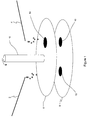
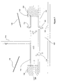
- Figure 1 shows a side view of a single-hole selector electrode according to an embodiment of the instant invention
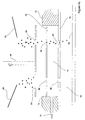
- Figure 2a is a schematic diagram of a single-hole selector electrode disposed adjacent and parallel to an outer electrode of a FAIMS analyzer, in a condition for introducing ions via a first ion inlet orifice;
- Figure 2b is a schematic diagram of a single-hole selector electrode disposed adjacent and parallel to an outer electrode of a FAIMS analyzer, in a condition for introducing ions via a second ion inlet orifice;
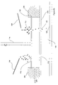
- Figure 3a is a schematic diagram of a single-hole selector electrode disposed adjacent and parallel to an outer electrode of a FAIMS analyzer, in a condition for selectively introducing ions in a FAIMS separation mode via a first ion inlet orifice into the FAIMS analyzer;
- Figure 3b is a schematic diagram of a single-hole selector electrode disposed adjacent and parallel to an outer electrode of a FAIMS analyzer, in a condition for selectively introducing ions in a total ion mode via a second ion inlet orifice into the FAIMS analyzer;
- Figure 4a shows an embodiment of the instant invention including both a rotating selector electrode and a curtain plate, in a first mode of operation
- Figure 5 shows patterns of the flow of gases supplied to the curtain region of the system of Figures 4a and 4b, when in the second mode of operation;
- Figure 6 shows the system of Figures 4a and 4b adapted for the special case of LockSprayTM
- Figure 8a shows the system of Figure 7 in a first mode of operation
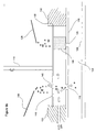
- Figure 8b shows the system of Figure 7 in a second mode of operation
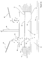
- Figure 9a shows a cross sectional view of an ion introduction region of a system according to another embodiment of the instant invention, in a first mode of operation
- Figure 9b shows the system of Figure 9a in a second mode of operation
- Figure 10a shows a top view of a single-hole selector electrode
- Figure 10b shows a top view of a multiple-hole selector electrode
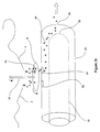
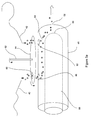
- Figure 10c shows a top view of a notched selector electrode
- Figure 11 is a simplified flow diagram of a method of separating ions according to an embodiment of the instant invention.
- Figure 12 is a simplified flow diagram of another method of separating ions according to an embodiment of the instant invention.
- Figure 1 is a schematic diagram that shows two atmospheric pressure ionization sources, in the form of a first electrospray needle 2 and a second electrospray needle 4, spraying ions toward a single-hole selector electrode 6 that is positioned adjacent and parallel to a lower plate 8 which has two openings 10 and 12 defined therethrough.
- Lower plate 8 with the two openings 10 and 12 is a portion of one of a curtain plate and an outer electrode of a not illustrated FAIMS analyzer. Both cases will be considered in greater detail, below.
- the single-hole selector electrode 6 includes a single opening 14 defined therethrough and is mounted to a drive shaft 16.
- FIG. 2a shown is a single-hole selector electrode disposed adjacent and parallel to an outer electrode of FAIMS. Elements labeled with the same numerals have the same function as those illustrated in Figure 1.
- the outer electrode 20 of FAIMS has two ion inlet orifices 22 and 24 defined therethrough and also defines an ion outlet orifice 26.
- An analyzer region 28 is defined by a space between the outer electrode 20 and an inner electrode 30 of the FAIMS.
- the inner electrode 30 includes a domed terminus 32 for directing ions along an average ion flow path within the analyzer region 28 that passes outwardly through the ion outlet orifice 26.
- both the first electrospray needle 2 and the second electrospray needle 4 are in continuous operation.
- the opening 14 in the single-hole selector electrode 6 is controllably alignable with the first ion inlet orifice 22 or the second ion inlet orifice 24 by rotation of the single-hole selector electrode 6 about a rotation axis aligned with the drive shaft 16.
- a not illustrated motor or other mechanical device actuates the drive shaft 16 to rotate the single-hole selector electrode 6 to adopt one of two possible rotational orientations.
- the single opening 14 is positioned adjacent to one of the ion inlet orifices 22 and 24 into FAIMS. By positioning this selector electrode, the user has the option of introducing ions from either, but not both, ion sources 2 and 4 into the FAIMS system at a time.
- the opening 14 is positioned to allow ions from the first electrospray needle 2 to pass into the analyzer region 28. Accordingly, a mixture of ions including different types of ions including an ion type of interest is introduced into the analyzer region 28 in Figure 2a.
- the ions of the mixture are separated according to the FAIMS principle as they traverse the analyzer region 28, and the ions passing out of FAIMS via the ion outlet orifice 26 are enriched in the ion type of interest.
- Types of ions other than the ion type of interest are selectively lost as a result of collisions with an electrode surface of the FAIMS.
- Ions produced by the first ionization source 2 impinge upon the single-hole selector electrode 6 at a point away from the opening 14 and are neutralized. Accordingly, in Figure 2b ions from the first ionization source 2 do not enter the FAIMS analyzer region 28.
- the first ionization source 2 is in communication with an outlet of a HPLC system and the second ionization source is in communication with the outlet of a GC system.
- sample eluted from one of the HPLC system and the GC system may be analyzed using the FAIMS system during a time of no sample elution from the other one of the HPLC system and the GC system. Since analysis by chromatographic or electrophoretic techniques is characterized by long periods of separation followed by a relatively short elution period, multiplexing several chromatographic or electrophoretic systems into a single FAIMS with rapid switching between sources is efficient.
- FIG. 3a and 3b shown is a single-hole selector electrode disposed adjacent and parallel to an outer electrode of FAIMS.
- the system shown at Figures 3a and 3b is a special case of the system that was described with reference to Figures 2a and 2b, above.
- Two atmospheric pressure ionization sources in the form of a first electrospray needle 40 and a second electrospray needle 42, are disposed for spraying ions toward a single-hole selector electrode 44 that is positioned adjacent and parallel to an outer electrode 46 of FAIMS.
- Two ion inlet orifices 48 and 50 are defined through the outer electrode 46.
- the outer electrode 46 also defines an ion outlet orifice 52.
- the first ion inlet orifice 48 is defined within a first portion of the outer electrode 46 such that ions introduced via the first ion inlet orifice 48 travel a first distance between the first ion inlet orifice 48 and the ion outlet orifice 52.
- the first distance is selected to provide an average ion flow path through the analyzer region 54 that is sufficiently long to support at least partial separation of a first type of ion contained in a mixture of ions introduced via the first ion inlet orifice 48, from a second type of ion contained in the same mixture.
- ions introduced into the analyzer region 54 via the first ion inlet orifice 48 are separated according to the FAIMS principle.
- the second ion inlet orifice 50 is defined within a second portion of the outer electrode 46 such that ions introduced via the second ion inlet orifice 50 travel a second distance between the second ion inlet orifice 50 and the ion outlet orifice 52, the second distance being shorter than the first distance.
- the second distance is selected to provide an average ion flow path through the analyzer region 54 that is sufficiently short to support transmission of plural types of ions contained in a mixture of ions introduced via the second ion inlet orifice 50.
- the FAIMS separation mechanism is effectively "turned off” for those ions introduced into the analyzer region 54 via the second ion inlet orifice 50.
- One non-limiting example of an application for the system that is shown in Figures 3a and 3b is for supporting a "total ion" mode of operation with the electric fields removed, and optionally a partial-separation FAIMS mode of operation without the need for changing electric field conditions within the FAIMS analyzer region 54.
- Another non-limiting example of an application for the system that is shown in Figures 3a and 3b is for supporting use of a LockMassTM or other calibration compound.
- both the first electrospray needle 40 and the second electrospray needle 42 are producing ions from a same sample material.
- FIG 3a when the opening 60 of the single-hole selector electrode 44 is aligned with the first ion inlet orifice 48, a mixture of ions is introduced via the first ion inlet orifice 48 and some types of ions are selectively transmitted through the analyzer region 54 to the ion outlet orifice 52.
- asymmetric waveform and compensation voltages only one or a relatively few types of ions are expected to be transmitted between the first ion inlet orifice 48 and the ion outlet orifice 52.
- the opening 60 of the single-hole selector electrode 44 is aligned with the second ion inlet orifice 50, a mixture of ions is introduced via the second ion inlet orifice 50.
- the voltages applied to the FAIMS electrodes are optionally removed, and may be replaced with voltages that result in very low electric fields in the analyzer region. Since the distance between the second ion inlet orifice 50 and the ion outlet 52 is short, substantially all types of ions are transmitted between the second ion inlet orifice 50 and the ion outlet orifice 52. Optionally, the applied asymmetric waveform and compensation voltages may remain applied. In this case some separation will proceed, but with limited effectiveness because of the short distance between the second ion inlet orifice 50 and the ion outlet orifice 52.
- FIG. 3a and 3b Another non-limiting example of an application for the system that is shown in Figures 3a and 3b is for supporting use of a LockMassTM or other calibration compounds.
- the calibration sample may contain precursor chemicals to provide one or more ions of known mass-to-charge (m/z) ratio so that the mass spectrometer mass-scale may be corrected regularly. Because of small physical changes inside the mass spectrometer the mass-scale may be highly accurate for limited periods of time, are therefore the mass-scale requires small refinements on a regular bases during the time when other types of ions of interest are being analyzed.
- the single-hole selector electrode 44 is aligned with the second ion inlet orifice 50 to support introduction of LockMassTM from the second electrospray needle 42. Since the LockMassTM compound can be provided at relatively high abundance, it is advantageous to be able to transmit the LockMassTM ions along a flow path through the analyzer region 54 that is short compared to a flow path for separating ions. In this way, the LockMassTM ions are introduced and pass through the FAIMS analyzer region 54 to a not illustrated mass spectrometer very rapidly. A delay time associated with the ions passing through a longer portion of the analyzer region 54 is avoided.
- the flows of gas have been omitted for the sake of clarity. It is advantageous to provide a curtain gas between the single-hole selector electrode and the outer electrode of FAIMS.
- a flow of a carrier gas is provided within the analyzer region between the inner and outer FAIMS electrodes, to carry the ions along a direction toward the ion outlet.
- electrospray sources have been shown in the figures, many other ion sources can be used in this system including, but not restricted to atmospheric pressure chemical ionization, corona discharge, radioactivity (Ni foil), laser or high energy photons (MALDI, photoionization).
- each electrospray needle or other ion source components
- the rotating selector electrode to the curtain plate and outer FAIMS electrode to form a voltage gradient to drive the ions from the electrospray needle into the FAIMS analyzer region.
- a strong electric field around the tip of the electrospray needle is required to produce a fine spray of liquid droplets, and the formation of ions.
- Typical voltages applied for production of positive ions would be: needles at about 3000 volts, the selector electrode at 1000 volts, the curtain plate slightly lower than 1000 and the outer electrode at close to zero volts respectively.
- FIG. 4a and 4b shown is a system in which a single-hole selector electrode is disposed adjacent and parallel to a curtain plate of a FAIMS analyzer.
- the curtain plate 70 is mounted into gas tight connection with an insulator 72 that forms a chamber 74 between the curtain plate 70 and an upper electrode 76 of FAIMS.
- a flow of curtain gas 78 is delivered to the chamber 74.
- Figures 4a and 4b show ions being selected from one of a first electrospray needle 80 and a second electrospray needle 82, respectively, by rotation of a single-hole selector electrode 84 so that a single hole 86 in the single-hole selector electrode 84 is adjacent to one of the first electrospray needle 80 and second electrospray needle 82, respectively.
- a not illustrated motor or other mechanical device actuates a drive shaft 99 to rotate the single-hole selector electrode 84 to adopt one of two possible rotational orientations.
- the single-hole selector electrode 84 the user has the option of permitting ions from either, but not both, the first electrospray needle 80 and second electrospray needle 82 to enter the FAIMS system.
- the single-hole selector electrode 84 is parallel and adjacent to the curtain plate 70, which has two orifices 88 and 90 defined therethrough.
- the upper electrode 76 of FAIMS also has two openings 92 and 94 defined therethrough and that are aligned with the orifices 88 and 90 in the curtain plate 70.
- a not illustrated portion of the curtain gas 78 flows outward through the curtain plate towards the ion source helping to desolvate the ions as they approach the curtain plate.
- a second (optional) portion of the gas 78 flows into FAIMS to contribute to (or constitute) the carrier gas that transports the ions through the analyzer region 96 of FAIMS.
- the flow of gases that are chosen is dependent on the type ion ionization source that is employed with the present invention. The gases discussed here are specific for the operation of an atmospheric pressure electrospray ionization system. Additionally, in some cases the source of ions may be operated at elevated or reduced temperatures, requiring isolation of FAIMS in order to operate FAIMS at optimum temperature for ion separation and ion transmission.
- FIG. 5 shown is the system of Figures 4a and 4b in which gas flows are illustrated but ions have been omitted for clarity. Elements labeled with the same numerals have the same function as those illustrated in Figures 4a and 4b. Since there are two openings 92 and 94 through the outer electrode 76 of FAIMS, a portion of the curtain gas optionally flows into each of these openings. The flow from the curtain region 74 into FAIMS through these two openings 92 and 94 optionally is reduced to approximately zero by providing a carrier gas to the analyzer region 96 independently.
- the transmission of ions into the FAIMS analyzer is more efficient if a flow of gas aids transport of the ions from the chamber 74 between the curtain plate 70 and outer electrode 76 and into FAIMS.
- the curtain gas preferably flows outward through both openings 88 and 90 in the curtain plate 70, as shown in Figure 5.
- the single-hole selector electrode 84 is in close proximity or in sliding contact (and at the same electrical potential) with the curtain plate 70, thus always covering one (or both) of the holes in the curtain plate 70. It is advantageous in this case to switch rapidly between the two positions, to minimize the disturbance in the gas flows when the two holes in the curtain plate are simultaneously closed.
- FIG. 6 illustrates the special case of LockSprayTM used with Waters high resolution TOF mass spectrometers.
- the first electrospray needle 80 is used to produce ions of the samples that are being analyzed, while the second electrospray needle 82 is used for producing ions of the calibration compound.
- the ions from the second electrospray needle 82 are used for calibrating the mass-scale of the high resolution TOF mass spectrometer, and are passed only occasionally along a calibration channel through FAIMS for short periods of time to permit re-calibration of the mass spectrometer.
- the opening 100 in the curtain plate 70 and the opening 102 in the outer electrode 76 of FAIMS are smaller for the calibration channel than the openings used for the analytical channel.
- the number of ions of the calibration compound arriving at the detector is increased by increasing the concentration of the calibration compound delivered to second electrospray needle 82, thus minimizing the need for high sensitivity through use of large apertures through the curtain plate and outer electrode of FAIMS along the calibration channel.
- FIG 7 illustrates in cross section an ion introduction region of a system according to an embodiment of the instant invention.
- a single-hole selector electrode 110 replaces the curtain plate 70 that is shown in Figures 4a through 6.
- the single-hole selector electrode 110 includes a single opening 112 defined therethrough and is mounted to a drive shaft 114.
- an upper electrode 116 of FAIMS has a first ion inlet orifice 118 and a second ion inlet orifice 120 defined therethrough.
- An analyzer region 122 is defined by a space between the upper electrode 116 and a lower electrode 124 of the FAIMS.
- both a first electrospray needle 126 and a second electrospray needle 128 are in continuous operation.
- the opening 112 in the single-hole selector electrode 110 is controllably alignable with the first ion inlet orifice 118 or the second ion inlet orifice 120 by rotation of the single-hole selector electrode 110 about a rotation axis aligned with the drive shaft 114.
- a not illustrated motor or other mechanical device actuates the drive shaft 114 to rotate the single-hole selector electrode 110 to adopt one of two possible rotational orientations.
- the single opening 112 is positioned adjacent to one of the ion inlet orifices 118 and 120 into FAIMS.
- the electrically insulating material 130 is disposed adjacent to the upper electrode 116 and forms a substantially gas-tight seal with the upper electrode 116, so as to define a curtain gas region proximate the first ion inlet orifice 118 and the second ion inlet orifice 120.
- the curtain plate 70 of Figure 6 is a part of the gas-tight region into which curtain gas is delivered, and it is easier to maintain a gas-tight seal with a stationary, non-moving curtain plate 70.
- Figures 8a and 8b illustrate the flow of ions through the system of Figure 7 when the single-hole selector electrode 110 is aligned with the first ion inlet orifice 118 and the second ion inlet orifice 120, respectively. Elements labeled with the same numerals have the same function as those illustrated in Figure 7.
- the periods of time at each of the two possible points of rotation, and the timing of the selection of each ion source is controlled from a master computer system (not shown).
- Figures 9a and 9b show an ion introduction region similar to that discussed with reference to Figures 7 through 8b, but including a modified single-hole selector electrode. Elements labeled with the same numerals have the same function as those illustrated in Figures 7, 8a and 8b.
- a single-hole selector electrode 140 has an extension 144 from the surface facing the upper electrode 116 of FAIMS, which extension 144 serves to reduce or eliminate the flow of gas into the non-active orifice (e.g. the first ion inlet orifice 118 in Figure 9a and the second ion inlet orifice 120 in Figure 9b) in the upper electrode 116 of FAIMS.
- the non-active orifice e.g. the first ion inlet orifice 118 in Figure 9a and the second ion inlet orifice 120 in Figure 9b
- an active orifice e.g. the second ion inlet orifice 120 in Figure 9a and the first ion inlet orifice 118 in Figure 9b
- an active orifice e.g. the second ion inlet orifice 120 in Figure 9a and the first ion inlet orifice 118 in Figure 9b
- Figure 9a ions from the second electrospray needle 128 are selectively passed into the FAIMS analyzer region 122 after passing through the opening 142 and the second ion inlet orifice 120.
- ions from the first electrospray needle 126 are selectively passed into the FAIMS analyzer region 122 after passing through the opening 142 and the first ion inlet orifice 118.
- the extension 144 is optionally a small disc of insulating material, such as for instance PEEK or TeflonTM, that makes contact with the upper electrode 116 of FAIMS, so as to make gas-tight contact with the upper electrode 116 while covering one of the ion inlet orifices 118 and 120.
- the extension 144 is optionally a short cylinder only slightly wider in diameter than a larger one of the ion inlet orifices 118 and 120 (e.g. if one of the orifices 118 and 120 is dimensioned smaller than the other for LockMassTM applications), and therefore does not interfere substantially with the gas flow elsewhere in the region between the single-hole selector electrode 140 and the upper electrode 116 of FAIMS.
- extension 144 is a conductive material, electrical contact with the upper electrode 116 must be avoided.
- a small disc of insulator is mounted to the lower surface of the extension 144 to avoid electrical contact when the extension 144 is fabricated from a conductive material, and to provide complete closure of the opening in the upper electrode 116 of FAIMS. Since during use the pressure differences are small between the analyzer region and the curtain gas region, absolute gas-tight closure is not essential for significantly reducing the flow of gas through the non-active orifice in the upper electrode of FAIMS 116.
- first ion inlet orifice is defined within a first portion of the upper FAIMS electrode such that ions introduced via the first ion inlet orifice travel a first distance between the first ion inlet orifice and an ion outlet orifice.
- the first distance is selected to provide an average ion flow path through the analyzer region of FAIMS that is sufficiently long to support at least partial separation of a first type of ion contained in a mixture of ions introduced via the first ion inlet orifice, from a second type of ion contained in the same mixture.
- ions introduced into the analyzer region of FAIMS via the first ion inlet orifice are separated according to the FAIMS principle.
- the second ion inlet orifice is defined within a second portion of the upper electrode of FAIMS such that ions introduced via the second ion inlet orifice travel a second distance between the second ion inlet orifice and the ion outlet orifice, the second distance being shorter than the first distance.
- the second distance is selected to provide an average ion flow path through the analyzer region of FAIMS that is sufficiently short to support transmission of all types of ions contained in a mixture of ions introduced via the second ion inlet orifice.
- this optional arrangement supports both a “total ion” mode of operation and use of a LockMassTM or other calibration compound, as described above with reference to Figures 3a and 3b.
- the second ion inlet orifice is defined within a second portion of the upper electrode of FAIMS such that ions introduced via the second ion inlet orifice travel a second distance between the second ion inlet orifice and the ion outlet orifice.
- the second distance is shorter than the first distance but is sufficiently long to support at least partial separation of a first type of ion contained in a mixture of ions introduced via the second ion inlet orifice, from a second type of ion contained in the same mixture.
- this latter arrangement supports rapid sequencing between different ionization sources and/or different samples.
- the ion type of interest produced by the first electrospray needle and the ion type of interest produced by the second electrospray are different types of ions.
- one of the first electrospray needle and the second electrospray needle is substituted by a different type of ionization source.
- the sample is provided to each of the first electrospray needle and the second electrospray needle after separation using a chromatographic or electrophoretic technique.
- the first electrospray needle is in communication with an outlet of a HPLC system and the second electrospray needle is in communication with the outlet of a GC system.
- sample eluted from one of the HPLC system and the GC system may be analyzed using the FAIMS system during a time of no sample elution from the other one of the HPLC system and the GC system. Since analysis by chromatographic or electrophoretic techniques is characterized by long periods of separation followed by a relatively short elution period, multiplexing several chromatographic or electrophoretic systems into a single FAIMS with rapid switching between sources is efficient.
- the FAIMS of Figures 4a-9b was described in terms of an upper electrode and a lower electrode, such as for instance is found in a parallel plate geometry FAIMS, the description of the instant invention is equally applicable to other geometries of FAIMS, including but not limited to concentric cylinder geometry electrodes with or without a domed inner electrode; parallel plate geometry electrodes with either curved or flat electrode plates; concentric cylinder geometry electrodes operating in a side-to-side mode; spherical electrodes; quadrupolar electrodes; etc.
- the upper electrode is equivalent to an outer cylindrical electrode and the lower electrode is equivalent to an inner cylindrical electrode.
- Figure 10a shows a top view of a single-hole selector electrode similar to the one described with reference to Figures 1 through 8b.
- Figure 10b shows a double-hole selector electrode, in which rotation by 90° about a centrally mounted drive shaft is sufficient for switching between two ion inlet orifices into FAIMS.
- Figure 10c shows a notched selector electrode, in which a portion of the selector electrode is cut away or the electrode is formed absent at least a portion of a sector.
- the shape of the notch in Figure 10c is for illustrative purposes only, and other suitable shapes may be envisaged.
- Figure 10d shows an alternative arrangement in which a drive shaft is eccentrically mounted to the ion selector electrode. Only a relatively small amount of rotation, relative to other embodiments, about the drive shaft is required to switch between two ion inlet orifices into FAIMS. Preferably, a not-illustrated barrier is provided between the openings in the selector electrode so as to prevent possible cross-talk between the sources and the openings.
- a FAIMS analyzer region is provided in fluid communication with an ion detector.
- a first ionization source is provided in communication with a sample material including a precursor of an ion type of interest.
- a second ionization source is provided in communication with a sample material including the precursor of the ion type of interest.
- a mixture of ions is produced at step 1006, the mixture of ions comprising different types of ions including the ion type of interest.
- the ions are directed at step 1008 from the first ionization source along a path of a first length through the FAIMS analyzer region, the first length being sufficient to effect at least a partial separation of the ion type of interest from other types of ions that may be in the mixture.
- ions are detected at step 1010 after the ions have traveled the first length.
- a mixture of ions is produced at step 1012 comprising different types of ions including the ion type of interest.
- the ions are directed at step 1014 from the second ionization source along a path of a second length through the FAIMS analyzer region, the second length being insufficient to effect a separation of the ion type of interest from most other types of ions in the mixture.
- the ions are detected after the ions have traveled the second length.
- a FAIMS analyzer region is provided in fluid communication with an ion detector.
- a mixture of different types of ions including an ion type of interest is introduced into the analyzer region via a first ion inlet orifice.
- the ion type of interest is selectively transmited through the analyzer region and to the ion detector.
- ions of a calibration compound are introduced into the analyzer region via a second ion inlet orifice.
- the ions of a calibration compound are transmitted to the ion detector.
- the ion detector In dependence upon a response of the ion detector to the ions of a calibration compound, the ion detector initiates corrective action, if needed, at step 1030. Upon completion of this corrective action, the mixture of different types of ions including an ion type of interest is introduced into the analyzer region via a first ion inlet orifice, and this ion of interest is selectively transmitted through the analyzer region and to the ion detector. The measurements of the ion of interest taken after the corrective action are improved relative to those that would have been taken absent the corrective action.
Landscapes
- Physics & Mathematics (AREA)
- Chemical & Material Sciences (AREA)
- Spectroscopy & Molecular Physics (AREA)
- Analytical Chemistry (AREA)
- Life Sciences & Earth Sciences (AREA)
- Health & Medical Sciences (AREA)
- Electrochemistry (AREA)
- Chemical Kinetics & Catalysis (AREA)
- Biochemistry (AREA)
- General Health & Medical Sciences (AREA)
- General Physics & Mathematics (AREA)
- Immunology (AREA)
- Pathology (AREA)
- Other Investigation Or Analysis Of Materials By Electrical Means (AREA)
- Electron Tubes For Measurement (AREA)
Applications Claiming Priority (2)
| Application Number | Priority Date | Filing Date | Title |
|---|---|---|---|
| US54917004P | 2004-03-03 | 2004-03-03 | |
| US549170P | 2004-03-03 |
Publications (2)
| Publication Number | Publication Date |
|---|---|
| EP1580793A2 true EP1580793A2 (de) | 2005-09-28 |
| EP1580793A3 EP1580793A3 (de) | 2006-07-19 |
Family
ID=34860533
Family Applications (1)
| Application Number | Title | Priority Date | Filing Date |
|---|---|---|---|
| EP05405218A Withdrawn EP1580793A3 (de) | 2004-03-03 | 2005-03-02 | Verfahren und Gerät zur Auswahl von Einlässen eines FAIMS mit mehreren Einlässen |
Country Status (3)
| Country | Link |
|---|---|
| US (2) | US7223971B2 (de) |
| EP (1) | EP1580793A3 (de) |
| CA (2) | CA2499247A1 (de) |
Cited By (1)
| Publication number | Priority date | Publication date | Assignee | Title |
|---|---|---|---|---|
| KR102133334B1 (ko) * | 2020-02-25 | 2020-07-14 | 영인에이스 주식회사 | 질량분석기 |
Families Citing this family (31)
| Publication number | Priority date | Publication date | Assignee | Title |
|---|---|---|---|---|
| US7157700B2 (en) * | 2001-06-30 | 2007-01-02 | Sionex Corporation | System for collection of data and identification of unknown ion species in an electric field |
| US6806463B2 (en) * | 1999-07-21 | 2004-10-19 | The Charles Stark Draper Laboratory, Inc. | Micromachined field asymmetric ion mobility filter and detection system |
| US7399958B2 (en) | 1999-07-21 | 2008-07-15 | Sionex Corporation | Method and apparatus for enhanced ion mobility based sample analysis using various analyzer configurations |
| US6815669B1 (en) * | 1999-07-21 | 2004-11-09 | The Charles Stark Draper Laboratory, Inc. | Longitudinal field driven ion mobility filter and detection system |
| US7005632B2 (en) * | 2002-04-12 | 2006-02-28 | Sionex Corporation | Method and apparatus for control of mobility-based ion species identification |
| US7122794B1 (en) | 2002-02-21 | 2006-10-17 | Sionex Corporation | Systems and methods for ion mobility control |
| US7223971B2 (en) * | 2004-03-03 | 2007-05-29 | Thermo Finnigan Llc | Method and apparatus for selecting inlets of a multiple inlet FAIMS |
| CA2550088A1 (en) * | 2003-12-18 | 2005-07-07 | Sionex Corporation | Methods and apparatus for enhanced ion based sample detection using selective pre-separation and amplification |
| CA2551991A1 (en) * | 2004-01-13 | 2005-07-28 | Sionex Corporation | Methods and apparatus for enhanced sample identification based on combined analytical techniques |
| WO2005074584A2 (en) * | 2004-02-02 | 2005-08-18 | Sionex Corporation | Compact sample analysis systems and related methods using combined chromatography and mobility spectrometry techniques |
| EP1756561A1 (de) * | 2004-04-28 | 2007-02-28 | Sionex Corporation | System und verfahren zur ionenspeziesanalyse mit verbesserter zustandskontrolle und dateninterpretation unter verwendung differentieller mobilitätsspektrometer |
| CA2507480A1 (en) * | 2004-05-19 | 2005-11-19 | Ionalytics Corporation | Multiple nano-spray delivery system for faims |
| GB0424426D0 (en) | 2004-11-04 | 2004-12-08 | Micromass Ltd | Mass spectrometer |
| GB0503010D0 (en) * | 2005-02-14 | 2005-03-16 | Micromass Ltd | Mass spectrometer |
| EP1920243B1 (de) * | 2005-04-29 | 2015-09-09 | DH Technologies Development Pte. Ltd. | Kompakte auf gaschromatographie und ionenmobilität basierende probenanalysesysteme, -verfahren und -vorrichtungen |
| US7579589B2 (en) | 2005-07-26 | 2009-08-25 | Sionex Corporation | Ultra compact ion mobility based analyzer apparatus, method, and system |
| US7687771B2 (en) | 2006-01-12 | 2010-03-30 | Ionics Mass Spectrometry Group | High sensitivity mass spectrometer interface for multiple ion sources |
| GB0624740D0 (en) | 2006-12-12 | 2007-01-17 | Micromass Ltd | Mass spectrometer |
| US8158932B2 (en) * | 2010-04-16 | 2012-04-17 | Thermo Finnigan Llc | FAIMS having a displaceable electrode for on/off operation |
| GB201021360D0 (en) | 2010-12-16 | 2011-01-26 | Thermo Fisher Scient Bremen Gmbh | Apparatus and methods for ion mobility spectrometry |
| CN102568994B (zh) * | 2010-12-31 | 2014-08-06 | 同方威视技术股份有限公司 | 用于离子迁移谱仪的进样装置及其使用方法和离子迁移谱仪 |
| US9239279B1 (en) * | 2011-06-03 | 2016-01-19 | Arkansas State University—Jonesboro | Sequential differential mobility analyzer and method of using same |
| US8450681B2 (en) * | 2011-06-08 | 2013-05-28 | Mks Instruments, Inc. | Mass spectrometry for gas analysis in which both a charged particle source and a charged particle analyzer are offset from an axis of a deflector lens, resulting in reduced baseline signal offsets |
| GB201122267D0 (en) * | 2011-12-23 | 2012-02-01 | Micromass Ltd | Multi-pass ion mobility separation device with moving exit aperture |
| US9188570B2 (en) | 2012-11-13 | 2015-11-17 | Valco Instruments Company, L.P. | Photo ionization detector for gas chromatography having at least two separately ionizing sources |
| US8829914B2 (en) * | 2012-11-13 | 2014-09-09 | Valco Instruments Company, L.P. | Photo ionization detector for gas chromatography having two separately ionizing sources and methods of use |
| US10734213B2 (en) | 2013-07-31 | 2020-08-04 | Smiths Detection Inc. | Intermittent mass spectrometer inlet |
| CN106783505B (zh) * | 2016-12-30 | 2018-11-20 | 聚光科技(杭州)股份有限公司 | 大气压离子源的真空接口 |
| CN111812187B (zh) * | 2020-06-18 | 2022-11-29 | 桂林电子科技大学 | 应用于faims的多线程一体化集成式主控系统 |
| US20240085373A1 (en) * | 2021-02-24 | 2024-03-14 | Dh Technologies Development Pte. Ltd. | Dynamic heating of a differential mobility spectrometer cell |
| CN114334598A (zh) * | 2021-12-25 | 2022-04-12 | 广州禾信仪器股份有限公司 | 质谱仪、样品电离平台及其离子源 |
Family Cites Families (12)
| Publication number | Priority date | Publication date | Assignee | Title |
|---|---|---|---|---|
| US5420424A (en) * | 1994-04-29 | 1995-05-30 | Mine Safety Appliances Company | Ion mobility spectrometer |
| US6066848A (en) * | 1998-06-09 | 2000-05-23 | Combichem, Inc. | Parallel fluid electrospray mass spectrometer |
| US6621077B1 (en) | 1998-08-05 | 2003-09-16 | National Research Council Canada | Apparatus and method for atmospheric pressure-3-dimensional ion trapping |
| US6504149B2 (en) | 1998-08-05 | 2003-01-07 | National Research Council Canada | Apparatus and method for desolvating and focussing ions for introduction into a mass spectrometer |
| US7148477B2 (en) * | 1999-07-21 | 2006-12-12 | Sionex Corporation | System for trajectory-based ion species identification |
| US6690004B2 (en) * | 1999-07-21 | 2004-02-10 | The Charles Stark Draper Laboratory, Inc. | Method and apparatus for electrospray-augmented high field asymmetric ion mobility spectrometry |
| US6495823B1 (en) | 1999-07-21 | 2002-12-17 | The Charles Stark Draper Laboratory, Inc. | Micromachined field asymmetric ion mobility filter and detection system |
| EP1277045A2 (de) * | 1999-12-15 | 2003-01-22 | MDS Inc. | Parallele probenzufuhr in einem eletrosprühmassenspektrometer mit hilfe von elektronischer indexierung, basierend auf einer merzahl von ioneneilässen |
| EP1273029B8 (de) | 2000-03-14 | 2006-01-11 | National Research Council Canada | Faims apparatur und verfahren mit lasergestützter ionisationsquelle |
| AU2003201232A1 (en) * | 2002-02-08 | 2003-09-02 | Ionalytics Corporation | Faims with non-destructive detection of selectively transmitted ions |
| US7034286B2 (en) | 2002-02-08 | 2006-04-25 | Ionalytics Corporation | FAIMS apparatus having plural ion inlets and method therefore |
| US7223971B2 (en) * | 2004-03-03 | 2007-05-29 | Thermo Finnigan Llc | Method and apparatus for selecting inlets of a multiple inlet FAIMS |
-
2005
- 2005-03-02 US US11/068,767 patent/US7223971B2/en not_active Expired - Fee Related
- 2005-03-02 CA CA002499247A patent/CA2499247A1/en not_active Abandoned
- 2005-03-02 US US11/068,764 patent/US7041969B2/en not_active Expired - Fee Related
- 2005-03-02 CA CA002499115A patent/CA2499115A1/en not_active Abandoned
- 2005-03-02 EP EP05405218A patent/EP1580793A3/de not_active Withdrawn
Cited By (1)
| Publication number | Priority date | Publication date | Assignee | Title |
|---|---|---|---|---|
| KR102133334B1 (ko) * | 2020-02-25 | 2020-07-14 | 영인에이스 주식회사 | 질량분석기 |
Also Published As
| Publication number | Publication date |
|---|---|
| US20050194527A1 (en) | 2005-09-08 |
| US7223971B2 (en) | 2007-05-29 |
| US20050194532A1 (en) | 2005-09-08 |
| EP1580793A3 (de) | 2006-07-19 |
| US7041969B2 (en) | 2006-05-09 |
| CA2499247A1 (en) | 2005-09-03 |
| CA2499115A1 (en) | 2005-09-03 |
Similar Documents
| Publication | Publication Date | Title |
|---|---|---|
| US7223971B2 (en) | Method and apparatus for selecting inlets of a multiple inlet FAIMS | |
| US7034286B2 (en) | FAIMS apparatus having plural ion inlets and method therefore | |
| US6753522B2 (en) | FAIMS apparatus having plural ion inlets and method therefore | |
| JP4560656B2 (ja) | 質量分析計及び質量分析方法 | |
| EP1419517B1 (de) | Vorrichtung und verfahren zum multiplexen von sprühvorrichtungen in einer electrospray-ionenquelle | |
| US8759757B2 (en) | Interchangeable ion source for electrospray and atmospheric pressure chemical ionization | |
| US7005633B2 (en) | Method and apparatus for desolvating ions for introduction into a FAIMS analyzer region | |
| US20260079128A1 (en) | Structural analysis of ionised molecules | |
| CA2598305C (en) | Ion mobility spectrometer | |
| US7417225B2 (en) | Apparatus and method for adjustment of ion separation resolution in FAIMS | |
| US7217921B2 (en) | Method and apparatus for FAIMS for in-line analysis of multiple samples | |
| CA2603888A1 (en) | Atmospheric pressure ion source for mass spectrometry | |
| WO2009155082A1 (en) | A radio-frequency-free hybrid electrostatic/magnetostatic cell for transporting, trapping, and dissociating ions in mass spectrometers | |
| GB2501027A (en) | Solvent assisted inlet ionization (SAII) interfaces | |
| CA2418212C (en) | Multi-inlet mass spectrometer | |
| US7274014B2 (en) | Apparatus and method for adjustment of ion separation resolution in FAIMS | |
| Smith | An evaluation of miniaturised field asymmetric waveform ion mobility spectrometry hyphenated with time-of-flight mass spectrometry |
Legal Events
| Date | Code | Title | Description |
|---|---|---|---|
| PUAI | Public reference made under article 153(3) epc to a published international application that has entered the european phase |
Free format text: ORIGINAL CODE: 0009012 |
|
| AK | Designated contracting states |
Kind code of ref document: A2 Designated state(s): AT BE BG CH CY CZ DE DK EE ES FI FR GB GR HU IE IS IT LI LT LU MC NL PL PT RO SE SI SK TR |
|
| AX | Request for extension of the european patent |
Extension state: AL BA HR LV MK YU |
|
| PUAL | Search report despatched |
Free format text: ORIGINAL CODE: 0009013 |
|
| AK | Designated contracting states |
Kind code of ref document: A3 Designated state(s): AT BE BG CH CY CZ DE DK EE ES FI FR GB GR HU IE IS IT LI LT LU MC NL PL PT RO SE SI SK TR |
|
| AX | Request for extension of the european patent |
Extension state: AL BA HR LV MK YU |
|
| RIC1 | Information provided on ipc code assigned before grant |
Ipc: H01J 49/42 20060101ALI20060609BHEP Ipc: H01J 49/40 20060101ALI20060609BHEP Ipc: H01J 49/10 20060101ALI20060609BHEP Ipc: H01J 49/04 20060101AFI20050628BHEP |
|
| 17P | Request for examination filed |
Effective date: 20070117 |
|
| AKX | Designation fees paid |
Designated state(s): DE GB |
|
| RAP1 | Party data changed (applicant data changed or rights of an application transferred) |
Owner name: THERMO FINNIGAN LLC |
|
| 17Q | First examination report despatched |
Effective date: 20081008 |
|
| STAA | Information on the status of an ep patent application or granted ep patent |
Free format text: STATUS: THE APPLICATION IS DEEMED TO BE WITHDRAWN |
|
| 18D | Application deemed to be withdrawn |
Effective date: 20111001 |