EP1580838A1 - Dispositif de communication portatif avec rendement d'antenne élévé - Google Patents
Dispositif de communication portatif avec rendement d'antenne élévé Download PDFInfo
- Publication number
- EP1580838A1 EP1580838A1 EP04006810A EP04006810A EP1580838A1 EP 1580838 A1 EP1580838 A1 EP 1580838A1 EP 04006810 A EP04006810 A EP 04006810A EP 04006810 A EP04006810 A EP 04006810A EP 1580838 A1 EP1580838 A1 EP 1580838A1
- Authority
- EP
- European Patent Office
- Prior art keywords
- board
- antenna
- communication device
- portable communication
- ground plane
- Prior art date
- Legal status (The legal status is an assumption and is not a legal conclusion. Google has not performed a legal analysis and makes no representation as to the accuracy of the status listed.)
- Granted
Links
- 239000004020 conductor Substances 0.000 claims abstract description 12
- 230000002708 enhancing effect Effects 0.000 claims abstract description 4
- 239000000463 material Substances 0.000 claims description 10
- 230000001413 cellular effect Effects 0.000 claims description 5
- PEZNEXFPRSOYPL-UHFFFAOYSA-N (bis(trifluoroacetoxy)iodo)benzene Chemical group FC(F)(F)C(=O)OI(OC(=O)C(F)(F)F)C1=CC=CC=C1 PEZNEXFPRSOYPL-UHFFFAOYSA-N 0.000 claims 1
- 230000005855 radiation Effects 0.000 description 5
- 239000002184 metal Substances 0.000 description 3
- 238000010521 absorption reaction Methods 0.000 description 2
- 230000005540 biological transmission Effects 0.000 description 2
- 230000015556 catabolic process Effects 0.000 description 2
- 238000006731 degradation reaction Methods 0.000 description 2
- 230000009977 dual effect Effects 0.000 description 2
- 239000007787 solid Substances 0.000 description 2
- 230000001419 dependent effect Effects 0.000 description 1
- 230000000694 effects Effects 0.000 description 1
- 238000005538 encapsulation Methods 0.000 description 1
- 238000004804 winding Methods 0.000 description 1
Images
Classifications
-
- H—ELECTRICITY
- H01—ELECTRIC ELEMENTS
- H01Q—ANTENNAS, i.e. RADIO AERIALS
- H01Q9/00—Electrically-short antennas having dimensions not more than twice the operating wavelength and consisting of conductive active radiating elements
- H01Q9/04—Resonant antennas
- H01Q9/0407—Substantially flat resonant element parallel to ground plane, e.g. patch antenna
- H01Q9/0421—Substantially flat resonant element parallel to ground plane, e.g. patch antenna with a shorting wall or a shorting pin at one end of the element
-
- H—ELECTRICITY
- H01—ELECTRIC ELEMENTS
- H01Q—ANTENNAS, i.e. RADIO AERIALS
- H01Q1/00—Details of, or arrangements associated with, antennas
- H01Q1/12—Supports; Mounting means
- H01Q1/22—Supports; Mounting means by structural association with other equipment or articles
- H01Q1/24—Supports; Mounting means by structural association with other equipment or articles with receiving set
- H01Q1/241—Supports; Mounting means by structural association with other equipment or articles with receiving set used in mobile communications, e.g. GSM
- H01Q1/242—Supports; Mounting means by structural association with other equipment or articles with receiving set used in mobile communications, e.g. GSM specially adapted for hand-held use
- H01Q1/243—Supports; Mounting means by structural association with other equipment or articles with receiving set used in mobile communications, e.g. GSM specially adapted for hand-held use with built-in antennas
-
- H—ELECTRICITY
- H01—ELECTRIC ELEMENTS
- H01Q—ANTENNAS, i.e. RADIO AERIALS
- H01Q1/00—Details of, or arrangements associated with, antennas
- H01Q1/44—Details of, or arrangements associated with, antennas using equipment having another main function to serve additionally as an antenna, e.g. means for giving an antenna an aesthetic aspect
-
- H—ELECTRICITY
- H01—ELECTRIC ELEMENTS
- H01Q—ANTENNAS, i.e. RADIO AERIALS
- H01Q1/00—Details of, or arrangements associated with, antennas
- H01Q1/52—Means for reducing coupling between antennas; Means for reducing coupling between an antenna and another structure
- H01Q1/528—Means for reducing coupling between antennas; Means for reducing coupling between an antenna and another structure reducing the re-radiation of a support structure
-
- H—ELECTRICITY
- H04—ELECTRIC COMMUNICATION TECHNIQUE
- H04M—TELEPHONIC COMMUNICATION
- H04M1/00—Substation equipment, e.g. for use by subscribers
- H04M1/02—Constructional features of telephone sets
- H04M1/03—Constructional features of telephone transmitters or receivers, e.g. telephone hand-sets
Definitions
- the present invention relates to the field of antennas and more particularly to a portable communication device including an in-built antenna.
- PIFA Planar Inverted-F Antenna
- Antenna Planar Inverted-F Antenna
- Antenna Planar Inverted-F Antenna
- Antenna Planar Inverted-F Antenna
- Antenna Planar Inverted-F Antenna
- the space between the antenna element and the ground plane inside the L defines an antenna volume, which is interesting to use for placing of components and other units. It is in this regard interesting to use it in relation to acoustic elements, because these might not be that sensitive to the radiation from the antenna.
- a speaker can then for instance be provided in relation to a hole in the board in or close to the antenna volume.
- EP-1317116 describes a cellular phone having a board with a ground plane above which is placed a PIFA antenna for defining an antenna volume.
- the antenna volume is used for the placing of a loudspeaker.
- the loudspeaker is in the preferred embodiment of the document placed inside the antenna volume.
- Radiation is here partly absorbed by the speaker, which absorption is here limited through varying the escape path impedance for the created radiation. This varying is in the preferred embodiment provided through inserting inductances between the windings of the speaker and the electrical feeding connections of the speaker, which stops the radiofrequencies received by the speaker from reaching the ground plane.
- the speaker is placed on one side of the board, with one part extending into the antenna volume through a hole of the board, while the antenna is provided on the opposite side of the board.
- the hole is here the element that varies the escape path.
- the present invention is directed towards solving the problem of enhancing the performance of the in-built antenna in a portable communication device when the ground plane for the antenna has holes close to an antenna element.
- One object of the present invention is thus to provide a portable communication device that enhances the performance of an included in-built antenna when the ground plane for the antenna has holes close to an antenna element.
- a portable communication device comprising:
- a second aspect of the present invention is directed towards a portable communication device including the features of the first aspect, wherein the antenna element is positioned with at least one part at a distance above the board, for defining an antenna volume between the board and the antenna element, and said at least one hole is provided under the antenna element.
- a third aspect of the present invention is directed towards a portable communication device including the features of the second aspect, wherein the acoustic element is provided on another opposite side of the board.
- a fourth aspect of the present invention is directed towards a portable communication device including the features of the third aspect, wherein an acoustic box associated with the acoustic element is provided in the antenna volume.
- a fifth aspect of the present invention is directed towards a portable communication device including the features of the first aspect, wherein the material is a cover of the acoustic element made of an electrically conducting material.
- a sixth aspect of the present invention is directed towards a portable communication device including the features of the fifth aspect, wherein the cover is provided with sound apertures.
- a seventh aspect of the present invention is directed towards a portable communication device including the features of the first aspect, wherein the material is a mesh made of an electrically conducting material placed between the cover of the acoustic element and the board.
- An eighth aspect of the present invention is directed towards a portable communication device including the features of the first aspect, wherein the material is connected to the ground plane using electrically conducting springs.
- a ninth aspect of the present invention is directed towards a portable communication device including the features of the first aspect, wherein the material is connected to the ground plane using an electrically conducting gasket.
- a tenth aspect of the present invention is directed towards a portable communication device including the features of the first aspect, wherein the antenna element is a PIFA antenna element.
- An eleventh aspect of the present invention is directed towards a portable communication device including the features of the first aspect, wherein it is a cellular phone.
- the invention has the following advantages. It is cheap to produce. It allows dual use of the space on the board harbouring the antenna, such that an acoustic element is combined with the antenna, which saves space within the portable communication device for other units.
- the problem with degraded antenna efficiency is greater the bigger the holes are that are needed.
- This degraded antenna efficiency because of the holes is limited by the grounding made of conducting material related to the exterior of the acoustic element. It also allows the use of big speakers that have good sound properties while limiting the degradation of the antenna efficiency to a minimum.
- a portable communication device will now be described in relation to a cellular phone, which is a preferred variation of the invention.
- the phone is furthermore preferably a so-called stick type phone, but it can be other types of phones like clamshell phones.
- the portable communication device can also be another type of device, like a cordless phone, a communication module, a PDA or any other type of portable device communicating with radio waves.
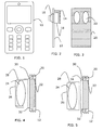
- Fig. 1 schematically shows a front view of a stick type phone according to the invention.
- the phone 10 includes a display and a keypad for viewing and entering information into the phone. It should be noted that the view does not show an antenna since this is inbuilt in the phone.
- Fig. 2 schematically shows a side view of a board 12 on which a number of elements relevant to the invention are shown. It should be realised that a lot more different elements in the form of components and units are in reality connected to this board, for instance a radio circuit for driving the antenna. The number of units has however been limited to a minimum in order to better explain the invention.
- the board 12 may either be a printed wire board or a printed circuit board.
- the board 12 has two sides, where an acoustic element in the form of a speaker 16 is provided on a first upper side facing a throughhole in the board, shown as a dashed area in the figure, and an antenna element 14 is provided on a second lower side opposite the first side and the speaker.
- the antenna element 14 is preferably a so called PIFA antenna (Planar Inverted-F Antenna), which has an L-shape, where one leg of the L is connected to the board at right angles and the other leg of the L is provided at a distance from the board essentially parallel with the board surface.
- the antenna element 14 is connected via electrical leads to both the ground plane and to the radio circuit provided on the board 12 for enabling transmission at suitable radio frequencies.
- the antenna element furthermore provides an antenna volume inside the "L”, in which an acoustic box 18 is provided, into which the speaker 16 emits sound.
- the board 12 also includes a ground plane (not shown), which runs in a layer within the board and stretches essentially along the whole length and width of the board. The hole provided for the speaker however also goes through this ground plane.
- Fig. 3 shows a front view of the ground plane 20 as a dashed area with the throughholes 22 provided for the previously described speakers.
- the holes are dimensioned according to the speakers and are here shown as being oval in shape. It should however be realised that they can have any shape that is suitable for connecting the speaker to the acoustic box of fig. 2, for instance having a circular shape. The shape can furthermore be dependent on the desired acoustical properties.
- the holes with the speaker and acoustic box together provide good acoustical properties for the speakers.
- the present invention is directed towards solving the problem associated with this degraded performance.
- this problem is solved through connecting electrically conducting material related to the exterior of the speaker to the ground plane.
- This material is preferably associated with the encapsulation of the speaker.
- the material is in one embodiment the casing of the speaker and in another embodiment a mesh provided between the hole and the speaker. In this way the performance is greatly enhanced.
- Fig. 4 shows one way of doing this according to a first embodiment of the invention.
- the speaker has a sound coil 24, which is encircled at its back and sides by a plastic casing 26.
- a metallic cover 28 On the front side of the plastic casing 26 there is provided a metallic cover 28, which also stretches down the sides of the speaker.
- the metallic cover 28 is provided with sound apertures on its front side, which is indicated by the cover being shown with a dashed line in this front area. The apertures are provided in order to allow the speaker to emit sound into the acoustic box provided in the antenna volume (not shown).
- the cover 28 and the rest of the speaker are positioned above the hole 22 in the board 12, in which board there is also shown the ground plane 20.
- the hole 22 is indicated in the drawing as a dashed area.
- this metallic cover 28 is connected to the ground plane 20 via two connections 30 and 32 one on each side of the hole 22, which greatly enhances the performance of the antenna.
- the other hole of the board has not been described here, but it has a speaker fastened to it in the same way as for the above-described hole.
- the speaker In operation of the speaker, the speaker emits sound into the acoustic box, which sound is then submitted to a user of the phone via an ear port connected to the box.
- the ear port is not shown in any of the drawings. This type of speaker is described in more detail in European patent application number 04003111.4, which is herein incorporated by reference.
- the ground plane is thus enlarged and the effect of the holes beneath the antenna volume are minimised. In this way unnecessary radiation that would be wasted if going through the hole is furthermore more or less eliminated.
- Fig. 5 shows another embodiment of the invention in the same view as fig. 4.
- This figure includes all the elements of fig. 4, but with one difference.
- a metallic mesh 34 which is connected to the ground plane 20 with connections 30 and 32 in the same way as the cover in fig. 4.
- the mesh 34 is indicated with a dashed line in fig. 5.
- the reason for this solution is that the cover 28 is not of an electrically conductive material. In order to provide the enlargement of the ground plane, the mesh 34 is therefore inserted, which provides the necessary enlargement of the ground plane.
- connection of the cover or the mesh to the ground plane could be provided in a multitude of ways. They can be provided using an electrically conducting gasket surrounding the cover and/or mesh. They can be provided using metal springs that are fastened in the hole of the board. Yet another alternative is that an electrically conducting speaker holder is soldered to the board in contact with the ground plane, into which holder the speaker including cover and/or mesh is attached using for instance springs. These are just a few of the ways in which the speaker can be attached to the ground plane.
- the antenna element can be a multiband antenna element designed for enabling transmission and reception at several frequency bands.
- the portable communication device has several advantages. It is cheap to produce. It allows dual use of the antenna volume, such that an acoustic element is combined with the antenna, which saves space within the portable communication device for other components and units.
- the problem with degraded antenna efficiency is greater the more and bigger holes that are needed. This degraded antenna efficiency because of the holes is limited by the grounding made of conducting material related to the exterior of the speaker. It also allows the use of big speakers that have good sound properties while limiting the degradation of the antenna efficiency to a minimum.
- the present invention can be varied in many ways in addition to those mentioned earlier. There can be more holes, but there might just be one.
- the grounding can furthermore be provided in only one position, two as in fig. 4 and 5 or more. In the case of a gasket, the grounding can be made along the whole circumference of the hole. It is also possible to provide the speaker inside the antenna volume instead of outside.
- the mesh and casing that are grounded need not be metallic. It is sufficient that they are made of electrically conducting materials. Thus the present invention is only to be limited by the following claims.
Landscapes
- Engineering & Computer Science (AREA)
- Computer Networks & Wireless Communication (AREA)
- Signal Processing (AREA)
- Telephone Set Structure (AREA)
- Support Of Aerials (AREA)
- Waveguide Aerials (AREA)
- Transceivers (AREA)
- Details Of Aerials (AREA)
Priority Applications (6)
| Application Number | Priority Date | Filing Date | Title |
|---|---|---|---|
| DE602004012227T DE602004012227T2 (de) | 2004-03-22 | 2004-03-22 | Tragbares Kommunikationsgerät |
| AT04006810T ATE388500T1 (de) | 2004-03-22 | 2004-03-22 | Tragbares kommunikationsgerät mit verbessertem antennenwirkungsgrad |
| EP04006810A EP1580838B1 (fr) | 2004-03-22 | 2004-03-22 | Dispositif de communication portatif avec rendement d'antenne élévé |
| US10/593,997 US7760145B2 (en) | 2004-03-22 | 2005-02-17 | Raising antenna efficiency for a portable communication device |
| PCT/EP2005/001582 WO2005096438A1 (fr) | 2004-03-22 | 2005-02-17 | Augmentation de l'efficacite d'une antenne pour un dispositif de communication portatif |
| CN2005800091866A CN1934749B (zh) | 2004-03-22 | 2005-02-17 | 提高便携式通信装置的天线功效 |
Applications Claiming Priority (1)
| Application Number | Priority Date | Filing Date | Title |
|---|---|---|---|
| EP04006810A EP1580838B1 (fr) | 2004-03-22 | 2004-03-22 | Dispositif de communication portatif avec rendement d'antenne élévé |
Publications (2)
| Publication Number | Publication Date |
|---|---|
| EP1580838A1 true EP1580838A1 (fr) | 2005-09-28 |
| EP1580838B1 EP1580838B1 (fr) | 2008-03-05 |
Family
ID=34854572
Family Applications (1)
| Application Number | Title | Priority Date | Filing Date |
|---|---|---|---|
| EP04006810A Expired - Lifetime EP1580838B1 (fr) | 2004-03-22 | 2004-03-22 | Dispositif de communication portatif avec rendement d'antenne élévé |
Country Status (6)
| Country | Link |
|---|---|
| US (1) | US7760145B2 (fr) |
| EP (1) | EP1580838B1 (fr) |
| CN (1) | CN1934749B (fr) |
| AT (1) | ATE388500T1 (fr) |
| DE (1) | DE602004012227T2 (fr) |
| WO (1) | WO2005096438A1 (fr) |
Cited By (3)
| Publication number | Priority date | Publication date | Assignee | Title |
|---|---|---|---|---|
| WO2008031276A1 (fr) * | 2006-09-13 | 2008-03-20 | E28 (Shanghai) Limited | Procédé destiné à augmenter l'efficacité de rayonnement d'une antenne de téléphone mobile |
| EP1936926A1 (fr) * | 2006-12-21 | 2008-06-25 | Sagem Communications | Dispositif de communication à écoute amplifiée omnidirectionnelle |
| WO2008157725A1 (fr) * | 2007-06-21 | 2008-12-24 | Apple Inc. | Antennes de dispositif électronique portable |
Families Citing this family (3)
| Publication number | Priority date | Publication date | Assignee | Title |
|---|---|---|---|---|
| KR101829835B1 (ko) * | 2011-08-03 | 2018-02-19 | 엘지전자 주식회사 | 이동 단말기 |
| US9876273B2 (en) | 2015-09-03 | 2018-01-23 | Apple Inc. | Electronic device having antenna on grounded speaker box |
| KR102567498B1 (ko) * | 2018-09-13 | 2023-08-16 | 삼성디스플레이 주식회사 | 커버 윈도우 및 이를 포함하는 표시장치 |
Citations (4)
| Publication number | Priority date | Publication date | Assignee | Title |
|---|---|---|---|---|
| WO2002035810A1 (fr) * | 2000-10-25 | 2002-05-02 | Siemens Aktiengesellschaft | Terminal de communication |
| US20020187758A1 (en) * | 2001-06-06 | 2002-12-12 | Juha Ylitalo | Method for improving acoustic properties of a terminal device and a terminal device |
| US20030068987A1 (en) * | 2001-09-13 | 2003-04-10 | Alcatel | Component for a wireless communication terminal constituting an antenna, loudspeaker and ringer |
| FR2837036A1 (fr) * | 2002-03-08 | 2003-09-12 | Sagem | Telephone mobile avec un organe integre dans le volume de l'antenne |
Family Cites Families (5)
| Publication number | Priority date | Publication date | Assignee | Title |
|---|---|---|---|---|
| US6262364B1 (en) * | 1997-06-24 | 2001-07-17 | Bridgestone Corporation | Electromagnetic-wave shielding and light transmitting plate |
| US6259418B1 (en) * | 2000-01-20 | 2001-07-10 | 3Com Corp. | Modified monopole antenna |
| US6266019B1 (en) * | 2000-07-21 | 2001-07-24 | Ericsson Inc. | System for increasing antenna efficiency |
| ES2239700T3 (es) * | 2001-11-30 | 2005-10-01 | Sagem Sa | Telefono movil con un elemento integrado en el espacio entre la antena y la placa base. |
| US6879849B2 (en) * | 2002-02-21 | 2005-04-12 | Telefonaktiebolaget L M Ericsson (Publ) | In-built antenna for mobile communication device |
-
2004
- 2004-03-22 EP EP04006810A patent/EP1580838B1/fr not_active Expired - Lifetime
- 2004-03-22 DE DE602004012227T patent/DE602004012227T2/de not_active Expired - Lifetime
- 2004-03-22 AT AT04006810T patent/ATE388500T1/de not_active IP Right Cessation
-
2005
- 2005-02-17 US US10/593,997 patent/US7760145B2/en not_active Expired - Fee Related
- 2005-02-17 CN CN2005800091866A patent/CN1934749B/zh not_active Expired - Fee Related
- 2005-02-17 WO PCT/EP2005/001582 patent/WO2005096438A1/fr not_active Ceased
Patent Citations (4)
| Publication number | Priority date | Publication date | Assignee | Title |
|---|---|---|---|---|
| WO2002035810A1 (fr) * | 2000-10-25 | 2002-05-02 | Siemens Aktiengesellschaft | Terminal de communication |
| US20020187758A1 (en) * | 2001-06-06 | 2002-12-12 | Juha Ylitalo | Method for improving acoustic properties of a terminal device and a terminal device |
| US20030068987A1 (en) * | 2001-09-13 | 2003-04-10 | Alcatel | Component for a wireless communication terminal constituting an antenna, loudspeaker and ringer |
| FR2837036A1 (fr) * | 2002-03-08 | 2003-09-12 | Sagem | Telephone mobile avec un organe integre dans le volume de l'antenne |
Cited By (5)
| Publication number | Priority date | Publication date | Assignee | Title |
|---|---|---|---|---|
| WO2008031276A1 (fr) * | 2006-09-13 | 2008-03-20 | E28 (Shanghai) Limited | Procédé destiné à augmenter l'efficacité de rayonnement d'une antenne de téléphone mobile |
| EP1936926A1 (fr) * | 2006-12-21 | 2008-06-25 | Sagem Communications | Dispositif de communication à écoute amplifiée omnidirectionnelle |
| FR2910765A1 (fr) * | 2006-12-21 | 2008-06-27 | Sagem Comm | Dispositif de communication a ecoute amplifiee omnidirectionnelle. |
| WO2008157725A1 (fr) * | 2007-06-21 | 2008-12-24 | Apple Inc. | Antennes de dispositif électronique portable |
| US7911387B2 (en) | 2007-06-21 | 2011-03-22 | Apple Inc. | Handheld electronic device antennas |
Also Published As
| Publication number | Publication date |
|---|---|
| ATE388500T1 (de) | 2008-03-15 |
| DE602004012227D1 (de) | 2008-04-17 |
| WO2005096438A1 (fr) | 2005-10-13 |
| CN1934749A (zh) | 2007-03-21 |
| US20070290945A1 (en) | 2007-12-20 |
| CN1934749B (zh) | 2011-07-06 |
| US7760145B2 (en) | 2010-07-20 |
| DE602004012227T2 (de) | 2009-03-19 |
| EP1580838B1 (fr) | 2008-03-05 |
Similar Documents
| Publication | Publication Date | Title |
|---|---|---|
| KR101787384B1 (ko) | 휴대용 단말기의 안테나 장치 | |
| CN202353552U (zh) | 电子设备 | |
| US7107016B2 (en) | Component for a wireless communication terminal constituting an antenna, loudspeaker and ringer | |
| US7183983B2 (en) | Dual-layer antenna and method | |
| KR101606145B1 (ko) | 휴대용 단말기의 안테나 장치 | |
| US8462056B2 (en) | Built-in antenna for portable terminal | |
| KR20010052509A (ko) | 다중 주파수 대역 안테나 | |
| EP1930981A1 (fr) | Appareil à antenne de type intégré pour terminal mobile | |
| EP1580838B1 (fr) | Dispositif de communication portatif avec rendement d'antenne élévé | |
| JP2006067133A (ja) | 折り畳み式携帯無線機 | |
| TW202220286A (zh) | 天線結構及具有該天線結構的無線通訊裝置 | |
| WO2007129410A1 (fr) | Module d'antenne et terminal de communication radio | |
| CN101728635B (zh) | 用于便携式无线终端的天线装置 | |
| US7250911B2 (en) | Placing of components on an antenna arrangement | |
| KR20120029988A (ko) | 휴대용 단말기의 안테나 장치 | |
| KR100881469B1 (ko) | 저주파 대역용 내장형 안테나 및 이를 이용한 안테나 장치 | |
| KR100987271B1 (ko) | 저주파 대역용 내장형 안테나 장치 | |
| KR100987238B1 (ko) | 저주파 대역용 내장형 안테나 | |
| CN1839513B (zh) | 天线装置上部件的放置 | |
| KR101783254B1 (ko) | 휴대용 단말기의 안테나 장치 | |
| EP1558008B1 (fr) | Dispositif de communication électronique mobile avec deux haut-parleurs plats | |
| JP2003037411A (ja) | 携帯用無線機 |
Legal Events
| Date | Code | Title | Description |
|---|---|---|---|
| PUAI | Public reference made under article 153(3) epc to a published international application that has entered the european phase |
Free format text: ORIGINAL CODE: 0009012 |
|
| AK | Designated contracting states |
Kind code of ref document: A1 Designated state(s): AT BE BG CH CY CZ DE DK EE ES FI FR GB GR HU IE IT LI LU MC NL PL PT RO SE SI SK TR |
|
| AX | Request for extension of the european patent |
Extension state: AL LT LV MK |
|
| 17P | Request for examination filed |
Effective date: 20060314 |
|
| AKX | Designation fees paid |
Designated state(s): AT BE BG CH CY CZ DE DK EE ES FI FR GB GR HU IE IT LI LU MC NL PL PT RO SE SI SK TR |
|
| 17Q | First examination report despatched |
Effective date: 20060508 |
|
| GRAP | Despatch of communication of intention to grant a patent |
Free format text: ORIGINAL CODE: EPIDOSNIGR1 |
|
| GRAS | Grant fee paid |
Free format text: ORIGINAL CODE: EPIDOSNIGR3 |
|
| GRAA | (expected) grant |
Free format text: ORIGINAL CODE: 0009210 |
|
| AK | Designated contracting states |
Kind code of ref document: B1 Designated state(s): AT BE BG CH CY CZ DE DK EE ES FI FR GB GR HU IE IT LI LU MC NL PL PT RO SE SI SK TR |
|
| REG | Reference to a national code |
Ref country code: GB Ref legal event code: FG4D |
|
| REG | Reference to a national code |
Ref country code: CH Ref legal event code: EP |
|
| REG | Reference to a national code |
Ref country code: IE Ref legal event code: FG4D |
|
| REF | Corresponds to: |
Ref document number: 602004012227 Country of ref document: DE Date of ref document: 20080417 Kind code of ref document: P |
|
| PG25 | Lapsed in a contracting state [announced via postgrant information from national office to epo] |
Ref country code: ES Free format text: LAPSE BECAUSE OF FAILURE TO SUBMIT A TRANSLATION OF THE DESCRIPTION OR TO PAY THE FEE WITHIN THE PRESCRIBED TIME-LIMIT Effective date: 20080616 Ref country code: FI Free format text: LAPSE BECAUSE OF FAILURE TO SUBMIT A TRANSLATION OF THE DESCRIPTION OR TO PAY THE FEE WITHIN THE PRESCRIBED TIME-LIMIT Effective date: 20080305 |
|
| PG25 | Lapsed in a contracting state [announced via postgrant information from national office to epo] |
Ref country code: AT Free format text: LAPSE BECAUSE OF FAILURE TO SUBMIT A TRANSLATION OF THE DESCRIPTION OR TO PAY THE FEE WITHIN THE PRESCRIBED TIME-LIMIT Effective date: 20080305 |
|
| NLV1 | Nl: lapsed or annulled due to failure to fulfill the requirements of art. 29p and 29m of the patents act | ||
| PG25 | Lapsed in a contracting state [announced via postgrant information from national office to epo] |
Ref country code: BE Free format text: LAPSE BECAUSE OF FAILURE TO SUBMIT A TRANSLATION OF THE DESCRIPTION OR TO PAY THE FEE WITHIN THE PRESCRIBED TIME-LIMIT Effective date: 20080305 Ref country code: SI Free format text: LAPSE BECAUSE OF FAILURE TO SUBMIT A TRANSLATION OF THE DESCRIPTION OR TO PAY THE FEE WITHIN THE PRESCRIBED TIME-LIMIT Effective date: 20080305 Ref country code: PL Free format text: LAPSE BECAUSE OF FAILURE TO SUBMIT A TRANSLATION OF THE DESCRIPTION OR TO PAY THE FEE WITHIN THE PRESCRIBED TIME-LIMIT Effective date: 20080305 |
|
| PG25 | Lapsed in a contracting state [announced via postgrant information from national office to epo] |
Ref country code: PT Free format text: LAPSE BECAUSE OF FAILURE TO SUBMIT A TRANSLATION OF THE DESCRIPTION OR TO PAY THE FEE WITHIN THE PRESCRIBED TIME-LIMIT Effective date: 20080805 Ref country code: SE Free format text: LAPSE BECAUSE OF FAILURE TO SUBMIT A TRANSLATION OF THE DESCRIPTION OR TO PAY THE FEE WITHIN THE PRESCRIBED TIME-LIMIT Effective date: 20080605 Ref country code: NL Free format text: LAPSE BECAUSE OF FAILURE TO SUBMIT A TRANSLATION OF THE DESCRIPTION OR TO PAY THE FEE WITHIN THE PRESCRIBED TIME-LIMIT Effective date: 20080305 Ref country code: SK Free format text: LAPSE BECAUSE OF FAILURE TO SUBMIT A TRANSLATION OF THE DESCRIPTION OR TO PAY THE FEE WITHIN THE PRESCRIBED TIME-LIMIT Effective date: 20080305 Ref country code: CZ Free format text: LAPSE BECAUSE OF FAILURE TO SUBMIT A TRANSLATION OF THE DESCRIPTION OR TO PAY THE FEE WITHIN THE PRESCRIBED TIME-LIMIT Effective date: 20080305 Ref country code: MC Free format text: LAPSE BECAUSE OF NON-PAYMENT OF DUE FEES Effective date: 20080331 |
|
| REG | Reference to a national code |
Ref country code: CH Ref legal event code: PL |
|
| ET | Fr: translation filed | ||
| PG25 | Lapsed in a contracting state [announced via postgrant information from national office to epo] |
Ref country code: RO Free format text: LAPSE BECAUSE OF FAILURE TO SUBMIT A TRANSLATION OF THE DESCRIPTION OR TO PAY THE FEE WITHIN THE PRESCRIBED TIME-LIMIT Effective date: 20080305 |
|
| PLBE | No opposition filed within time limit |
Free format text: ORIGINAL CODE: 0009261 |
|
| STAA | Information on the status of an ep patent application or granted ep patent |
Free format text: STATUS: NO OPPOSITION FILED WITHIN TIME LIMIT |
|
| PG25 | Lapsed in a contracting state [announced via postgrant information from national office to epo] |
Ref country code: CH Free format text: LAPSE BECAUSE OF NON-PAYMENT OF DUE FEES Effective date: 20080331 Ref country code: IE Free format text: LAPSE BECAUSE OF NON-PAYMENT OF DUE FEES Effective date: 20080325 Ref country code: LI Free format text: LAPSE BECAUSE OF NON-PAYMENT OF DUE FEES Effective date: 20080331 Ref country code: EE Free format text: LAPSE BECAUSE OF FAILURE TO SUBMIT A TRANSLATION OF THE DESCRIPTION OR TO PAY THE FEE WITHIN THE PRESCRIBED TIME-LIMIT Effective date: 20080305 Ref country code: DK Free format text: LAPSE BECAUSE OF FAILURE TO SUBMIT A TRANSLATION OF THE DESCRIPTION OR TO PAY THE FEE WITHIN THE PRESCRIBED TIME-LIMIT Effective date: 20080305 |
|
| 26N | No opposition filed |
Effective date: 20081208 |
|
| PG25 | Lapsed in a contracting state [announced via postgrant information from national office to epo] |
Ref country code: BG Free format text: LAPSE BECAUSE OF FAILURE TO SUBMIT A TRANSLATION OF THE DESCRIPTION OR TO PAY THE FEE WITHIN THE PRESCRIBED TIME-LIMIT Effective date: 20080605 |
|
| PG25 | Lapsed in a contracting state [announced via postgrant information from national office to epo] |
Ref country code: IT Free format text: LAPSE BECAUSE OF FAILURE TO SUBMIT A TRANSLATION OF THE DESCRIPTION OR TO PAY THE FEE WITHIN THE PRESCRIBED TIME-LIMIT Effective date: 20080305 |
|
| PG25 | Lapsed in a contracting state [announced via postgrant information from national office to epo] |
Ref country code: CY Free format text: LAPSE BECAUSE OF FAILURE TO SUBMIT A TRANSLATION OF THE DESCRIPTION OR TO PAY THE FEE WITHIN THE PRESCRIBED TIME-LIMIT Effective date: 20080305 |
|
| PG25 | Lapsed in a contracting state [announced via postgrant information from national office to epo] |
Ref country code: LU Free format text: LAPSE BECAUSE OF NON-PAYMENT OF DUE FEES Effective date: 20080322 Ref country code: HU Free format text: LAPSE BECAUSE OF FAILURE TO SUBMIT A TRANSLATION OF THE DESCRIPTION OR TO PAY THE FEE WITHIN THE PRESCRIBED TIME-LIMIT Effective date: 20080906 |
|
| PG25 | Lapsed in a contracting state [announced via postgrant information from national office to epo] |
Ref country code: TR Free format text: LAPSE BECAUSE OF FAILURE TO SUBMIT A TRANSLATION OF THE DESCRIPTION OR TO PAY THE FEE WITHIN THE PRESCRIBED TIME-LIMIT Effective date: 20080305 |
|
| PG25 | Lapsed in a contracting state [announced via postgrant information from national office to epo] |
Ref country code: GR Free format text: LAPSE BECAUSE OF FAILURE TO SUBMIT A TRANSLATION OF THE DESCRIPTION OR TO PAY THE FEE WITHIN THE PRESCRIBED TIME-LIMIT Effective date: 20080606 |
|
| REG | Reference to a national code |
Ref country code: FR Ref legal event code: PLFP Year of fee payment: 13 |
|
| PGFP | Annual fee paid to national office [announced via postgrant information from national office to epo] |
Ref country code: DE Payment date: 20160315 Year of fee payment: 13 |
|
| PGFP | Annual fee paid to national office [announced via postgrant information from national office to epo] |
Ref country code: FR Payment date: 20160223 Year of fee payment: 13 Ref country code: GB Payment date: 20160316 Year of fee payment: 13 |
|
| REG | Reference to a national code |
Ref country code: DE Ref legal event code: R119 Ref document number: 602004012227 Country of ref document: DE |
|
| GBPC | Gb: european patent ceased through non-payment of renewal fee |
Effective date: 20170322 |
|
| REG | Reference to a national code |
Ref country code: FR Ref legal event code: ST Effective date: 20171130 |
|
| PG25 | Lapsed in a contracting state [announced via postgrant information from national office to epo] |
Ref country code: DE Free format text: LAPSE BECAUSE OF NON-PAYMENT OF DUE FEES Effective date: 20171003 Ref country code: FR Free format text: LAPSE BECAUSE OF NON-PAYMENT OF DUE FEES Effective date: 20170331 |
|
| PG25 | Lapsed in a contracting state [announced via postgrant information from national office to epo] |
Ref country code: GB Free format text: LAPSE BECAUSE OF NON-PAYMENT OF DUE FEES Effective date: 20170322 |