EP1580863A1 - Halterung eines tragbaren elektronischen Gerätes mit Wärmefähigkeit - Google Patents
Halterung eines tragbaren elektronischen Gerätes mit Wärmefähigkeit Download PDFInfo
- Publication number
- EP1580863A1 EP1580863A1 EP04007342A EP04007342A EP1580863A1 EP 1580863 A1 EP1580863 A1 EP 1580863A1 EP 04007342 A EP04007342 A EP 04007342A EP 04007342 A EP04007342 A EP 04007342A EP 1580863 A1 EP1580863 A1 EP 1580863A1
- Authority
- EP
- European Patent Office
- Prior art keywords
- cradle
- electronic device
- handheld electronic
- casing
- air flow
- Prior art date
- Legal status (The legal status is an assumption and is not a legal conclusion. Google has not performed a legal analysis and makes no representation as to the accuracy of the status listed.)
- Granted
Links
Images



Classifications
-
- H—ELECTRICITY
- H04—ELECTRIC COMMUNICATION TECHNIQUE
- H04M—TELEPHONIC COMMUNICATION
- H04M1/00—Substation equipment, e.g. for use by subscribers
- H04M1/02—Constructional features of telephone sets
- H04M1/04—Supports for telephone transmitters or receivers
-
- G—PHYSICS
- G06—COMPUTING OR CALCULATING; COUNTING
- G06F—ELECTRIC DIGITAL DATA PROCESSING
- G06F1/00—Details not covered by groups G06F3/00 - G06F13/00 and G06F21/00
- G06F1/16—Constructional details or arrangements
- G06F1/1613—Constructional details or arrangements for portable computers
- G06F1/1632—External expansion units, e.g. docking stations
-
- G—PHYSICS
- G06—COMPUTING OR CALCULATING; COUNTING
- G06F—ELECTRIC DIGITAL DATA PROCESSING
- G06F1/00—Details not covered by groups G06F3/00 - G06F13/00 and G06F21/00
- G06F1/16—Constructional details or arrangements
- G06F1/20—Cooling means
-
- H—ELECTRICITY
- H02—GENERATION; CONVERSION OR DISTRIBUTION OF ELECTRIC POWER
- H02J—ELECTRIC POWER NETWORKS; CIRCUIT ARRANGEMENTS OR SYSTEMS FOR SUPPLYING OR DISTRIBUTING ELECTRIC POWER; SYSTEMS FOR STORING ELECTRIC ENERGY
- H02J7/00—Circuit arrangements for charging or discharging batteries or for supplying loads from batteries
- H02J7/70—Circuit arrangements for charging or discharging batteries or for supplying loads from batteries characterised by the mechanical construction
- H02J7/731—Circuit arrangements for charging or discharging batteries or for supplying loads from batteries characterised by the mechanical construction specially adapted for holding portable devices containing batteries
Definitions
- the present invention relates to a cradle for a handheld electronic device. More particularly, the present invention relates to a handheld electronic device cradle with enhanced heat-dissipating capability.
- handheld electronic devices are no longer used mainly for single-purposed information processing.
- the handheld electronic devices are now often used as a converged device for performing wireless communication, connecting to Internet, playing games and serving as a multi-media unit.
- the handheld electronic device is usually powered by a rechargeable battery, battery capacity is a principal factor determining the duration of operation of the handheld electronic device.
- the user When the electrical power of the rechargeable battery runs out, the user usually puts the handheld electronic device on a cradle which is connected with a power supply, whereby the battery can be charged.
- the temperature of the handheld electronic device will increase due to heat generated for charging the battery.
- the lift of the temperature of the handheld electronic device is exacerbated for a converged handheld electronic device, for example a smart phone, which has a variety of functions combined in a single device.
- the smart phone When the smart phone is put on the cradle, it simultaneously executes data exchange with a host computer connected with the cradle, and wireless communication with other mobile phones through a cellular phone network, in addition to the work that the battery in the smart phone is charged by the cradle.
- the temperature increased may exceed the rated temperature limitation of the smart phone. When this happens, the smart phone is not able to function normally. Moreover, the temperature increased may cause the battery to overheat, which could lead to a disastrous explosion. Therefore, how to effectively remove heat generated by the handheld electronic device from the device when it is put on the cradle for charging its battery becomes an issue to handheld electronic device manufacturers.
- an objective of the present invention is to provide a cradle for a handheld electronic device.
- the cradle can generate forced heat-dissipating air flow to cool down the temperature of the handheld electronic device mounted on the cradle for charging the battery of the device.
- the cradle can generate an air flow flowing from an interior of the handheld electronic device to an interior of the cradle to thereby take away heat generated by the device when it is mounted on the cradle for charging the battery of the device.
- the cradle can generate an air flow blowing toward a hot spot of a handheld electronic device seated on the cradle for battery charging.
- the invention provides a cradle for a handheld electronic device.
- the cradle provides electrical power to the handheld electronic device and connects the handheld electronic device to a host computer so that the handheld electronic device can exchange data with the host computer.
- the cradle also provides a forced air circulation to carry heat away from the handheld electronic device inserted in the cradle, thereby to prevent the handheld electronic device from overheating.
- the handheld electronic device has a first connection port.
- the cradle mainly comprises a casing, a second connection port and an electrical fan.
- the casing has an insertion slot.
- the second connection port is set up in the insertion slot of the casing for engaging with the first connection port of the handheld electronic device.
- the electrical fan is set up within the casing and is electrically connected to a power supply.
- the electrical fan is an axial fan..
- the casing has at least a ventilation slot that permits air inside the casing to leave therefrom.
- the cradle further includes a sealing element and a third connection port. The sealing element is set up inside the casing around the second connection port for fittingly engaging a bottom of the handheld electronic device.
- the third connection port is set up on the casing for electrically connecting with the power supply. Furthermore, the third connection port is electrically connected with the second connection port and can charge a spare rechargeable battery.
- the cradle further comprises a data exchange module.
- the data exchange module is set up inside the casing and electrically coupled to the second connection port.
- the data exchange module connects with a host computer through an electrical cable extending from the cradle so that the handheld electronic device can exchange data with the host computer.
- the bottom of the handheld electronic device has a heat-dissipating opening.
- the handheld electronic device further comprises a valve.
- the valve is a movable component capable of closing the heat-dissipating opening. When not inserted into the cradle, the valve closes the opening.
- the valve When inserted into the cradle, the valve is activated the leave the opening so that the opening is opened to an interior of the cradle.
- the electrical fan is activated to generate an air flow following from an interior of the handheld electronic device to enter the interior of the cradle via the heat-dissipating opening. Then, the air flow flows out of the cradle via the ventilation slot provided in the casing of the cradle.
- the cradle has an outer casing having an air inlet, an air outlet and an insertion slot.
- a fan-mounting seat is set up inside the outer casing and a blower type electrical fan is fastened to the fan-mounting seat.
- the cradle further comprises a cable for connecting with a host computer. When the handheld electronic device is plugged into the insertion slot, the cradle provides power to charge a rechargeable battery inside the handheld electronic device. Furthermore, the cradle provides a connection for exchanging data between the handheld electronic device and the host computer. Meanwhile, the electrical fan is activated to draw air into the cradle through the air inlet.
- the air entering the cradle is then blown out of the cradle through the air outlet and finally impinges at a region of an outer surface of the handheld electronic device where the battery of the handheld electronic device neighbors so that most of the heat produced by the device during its insertion in the cradle can be effectively carried away.
- Fig. 1 is a perspective view showing a cradle for handheld electronic device according to a first preferred embodiment of the present invention.
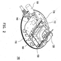
- Fig. 2 is a perspective view showing an interior of the cradle of Fig. 1.
- Fig. 3 is a perspective view showing a handheld electronic device for use with the cradle according to the first embodiment of the present invention.
- Fig. 4 is a perspective view showing the cradle of the first embodiment with the handheld electronic device of FIG. 3 and a spare rechargeable battery inserted therein.
- Fig. 5 is a partially enlarged view of a bottom of the handheld electronic device of Fig. 3 showing a heat dissipation opening thereof.
- Fig. 6 is a perspective view showing a cradle for handheld electronic device according to a second embodiment of the present invention, wherein a handheld electronic device is inserted in the cradle.
- Fig. 1 is a perspective view showing a cradle 100 for handheld electronic device according to a first preferred embodiment of the present invention.
- Fig. 2 is a perspective view showing that a casing 110 of the cradle 100 of Fig. 1 is removed so that an interior of the cradle 100 can be seen.
- Fig. 3 is a perspective view of a handheld electronic device 200 for use with the cradle 100.
- the cradle 100 mainly comprises the casing 110, a second connection port 120 and an electrical fan 150.
- the cradle 100 provides electrical power to a handheld electronic device 200 for charging a battery (not shown) inside the handheld electronic device 200 and performing data exchange for the handheld electronic device 200 with a host computer (not shown) connected to the cradle 100 via a cable 101 of the cradle 100.
- the handheld electronic device 200 has a first connection port 210.
- the handheld electronic device 200 in the present embodiment is, for example, a smart mobile phone with data processing and wireless communication capabilities, which is a CDMA (Code-Division Multiple Access) smart phone in particular.
- CDMA Code-Division Multiple Access
- the casing 110 has an insertion slot 114 for accommodating the handheld electronic device 200.
- the second connection port 120 is set up inside the insertion slot 114 of the casing 110 for engaging with the first connection port 210 of the handheld electronic device 200 and electrically connecting to an external power supply 130.
- the power supply 130 is a common indoor AC/DC adapter for connecting with an AC socket.
- the cradle 100 further comprises a data exchange module 140 set up inside the casing 110 and electrically connected to the second connection port 120.
- the data exchange module 140 is connected to a host computer through the electrical cable 101 having a universal serial bus (USB) connector (not shown) or other type connector that can electrically connect with the host computer.
- the host computer can be a notebook computer or a desktop computer.
- all the functions (including wireless communication) provided by the handheld electronic device 200 can operate normally without any overheating when the handheld electronic device 200 is plugged into the insertion slot 114 of the cradle 100 to charge the battery and perform data exchange and wireless communication.
- the electrical fan 150 is set up inside the casing 110 and electrically connected to the power supply 130 for cooling the handheld electronic device 200.
- the fan 150 in this embodiment is a mass flow axial fan for drawing hot air from the handheld electronic device 200.
- the casing 110 has at least a ventilation slot 112 to provide the cradle 110 with an air outlet.
- the ventilation slot 112 is positioned close to the second connection port 120 so that heat can be directly removed from the handheld electronic device 200.
- An activation of the fan 150 forms an air flow to flow from an interior of the handheld electronic device 200 into the interior of the casing 100. Then the air flow leaves the interior of the casing 100 via the ventilation slot 112.
- heat produced by the handheld electronic device 200 during its insertion in the cradle 100 is carried away.
- the heat is generated mainly by an operation of a CPU (not shown) and the charging of the battery of handheld electronic device 200.
- the cradle 100 further comprises a sealing element 160.
- the sealing element 160 is set up inside the casing 110 around the second connection port 120.
- the sealing element 160 fittingly engages a bottom of the handheld electronic device 200 around the first connection port 210.
- the sealing element 160 is fabricated using an elastic material such as rubber.
- Fig. 4 is a perspective view showing a handheld electronic device 200 and a spare rechargeable battery 220 inserted into the cradle 100 according to the first preferred embodiment of the present invention.
- the cradle 100 further comprises a third connection port 170.
- the third connection port 170 is set up on the casing 110 and electrically connected to the power supply 130.
- the third connection port 110 is electrically connected to the spare rechargeable battery 220 for recharging the spare rechargeable battery 220.
- the cradle 100 can provide electrical power to charge the spare rechargeable battery 220 and the built-in battery inside the handheld electronic device 200 in addition to providing the electrical power necessary for the handheld electronic device 200 to perform the data exchange operation with the host computer and wireless communication with other wireless device via a wireless communication network.
- the handheld electronic device 200 has an outer casing 205 with a heat-dissipating opening 240 therein.
- the first connection port 210 is set up in the bottom of the outer casing 205, and used for connecting with the second connection port 120 in the cradle 100.
- the air flow generated by the fan 150 draws the hot air in the handheld device out via the opening 240.
- Fig. 5 is a partially enlarged view of the bottom of the outer casing 205 of the handheld electronic device 200 shown in Fig. 3.
- the handheld electronic device 200 further comprises a valve 250.
- the valve 250 is a movable flap mounted on the outer casing 205.
- the valve 250 is devised to open or block the heat-dissipating opening 240. In normal use when the handheld electronic device 200 is not inserted in the cradle 100, the valve 250 covers the heat-dissipating opening 240 to prevent dust and dirt from entering the handheld electronic device 200.
- the cradle 100 has a valve-opening element (not shown) for opening the valve 250 when the handheld electronic device 200 is placed in the cradle 100.
- the valve 250 is a spring-loaded, pivotably connected door, and the valve-opening element is a post.
- the valve-opening element pushes the valve upwardly to open the opening 240 so that the interior of the handheld electronic device communicates with the interior of the cradle.
- Fig. 6 is a perspective view showing a handheld electronic device 380 plugged into a cradle 300 according to a second preferred embodiment of the present invention.
- the cradle 300 has a casing 310 with an insertion slot 311 and a cable 314 for connecting with a host computer (not shown).
- the handheld electronic device 380 is inserted into the insertion slot 311.
- the cradle 300 charges a built-in battery (not shown) inside the handheld electronic device 380 and connects the handheld electronic device 380 with the host computer to perform data exchange.
- the handheld electronic device 380 also communicates with other electronic devices by wireless communication.
- the casing 310 has substantially vertically oriented air inlet slots 352 facing rearwards and substantially horizontally oriented air outlet slots 312 facing upwards.
- the air inlet slots 352 and the air outlet slots 312 are generally perpendicular to each other.
- a fan-mounting seat 350 is set up in the casing 310 between the air inlet slots 352 and the air outlet slots 312.
- An electric fan 351, for example, a blower type fan is fixed to the fan-mounting seat 350. When the fan 351 is activated, the fan 351 generates an air flow that enters the cradle 300 via the air inlet slots 352 and leaves the cradle 300 via the air outlet slots 312.
- the air flow After leaving the outlet slots 312, the air flow impinges at a region of a rear side of handheld electronic device 380 where the built-in battery of the handheld electronic device 380 neighbors.
- heat generated by handheld electronic device 380 during its insertion in the cradle 380 can be carried away by the air flow.
- the handheld electronic devices 200, 380 in the two embodiments are prevented from performing some functions, like the wireless communication, if the handheld electronic devices are not charged by the cradles 100, 300, but by a traveling charger which does not have the forced-air cooling ability of the cradles according to the present invention.
- the invention provides a cradle with an electric fan for producing a forced air circulation.
- the forced air circulation heat produced by any handheld electronic device placed in the cradle is rapidly carried away so that the worry that the device may be damaged due to too heat can be ceased.
Landscapes
- Engineering & Computer Science (AREA)
- Theoretical Computer Science (AREA)
- Human Computer Interaction (AREA)
- Physics & Mathematics (AREA)
- General Engineering & Computer Science (AREA)
- General Physics & Mathematics (AREA)
- Power Engineering (AREA)
- Signal Processing (AREA)
- Computer Hardware Design (AREA)
- Charge And Discharge Circuits For Batteries Or The Like (AREA)
- Cooling Or The Like Of Electrical Apparatus (AREA)
- Telephone Function (AREA)
Priority Applications (2)
| Application Number | Priority Date | Filing Date | Title |
|---|---|---|---|
| EP10165328A EP2221939A3 (de) | 2004-03-26 | 2004-03-26 | Halterung eines tragbaren elektronischen Gerätes mit Wärmefähigkeit |
| EP04007342.1A EP1580863B1 (de) | 2004-03-26 | 2004-03-26 | Halterung eines tragbaren elektronischen Gerätes mit verbesserter Wärmeableitungsfähigkeit |
Applications Claiming Priority (1)
| Application Number | Priority Date | Filing Date | Title |
|---|---|---|---|
| EP04007342.1A EP1580863B1 (de) | 2004-03-26 | 2004-03-26 | Halterung eines tragbaren elektronischen Gerätes mit verbesserter Wärmeableitungsfähigkeit |
Related Child Applications (1)
| Application Number | Title | Priority Date | Filing Date |
|---|---|---|---|
| EP10165328A Division-Into EP2221939A3 (de) | 2004-03-26 | 2004-03-26 | Halterung eines tragbaren elektronischen Gerätes mit Wärmefähigkeit |
Publications (2)
| Publication Number | Publication Date |
|---|---|
| EP1580863A1 true EP1580863A1 (de) | 2005-09-28 |
| EP1580863B1 EP1580863B1 (de) | 2016-11-23 |
Family
ID=34854634
Family Applications (2)
| Application Number | Title | Priority Date | Filing Date |
|---|---|---|---|
| EP04007342.1A Expired - Lifetime EP1580863B1 (de) | 2004-03-26 | 2004-03-26 | Halterung eines tragbaren elektronischen Gerätes mit verbesserter Wärmeableitungsfähigkeit |
| EP10165328A Withdrawn EP2221939A3 (de) | 2004-03-26 | 2004-03-26 | Halterung eines tragbaren elektronischen Gerätes mit Wärmefähigkeit |
Family Applications After (1)
| Application Number | Title | Priority Date | Filing Date |
|---|---|---|---|
| EP10165328A Withdrawn EP2221939A3 (de) | 2004-03-26 | 2004-03-26 | Halterung eines tragbaren elektronischen Gerätes mit Wärmefähigkeit |
Country Status (1)
| Country | Link |
|---|---|
| EP (2) | EP1580863B1 (de) |
Cited By (1)
| Publication number | Priority date | Publication date | Assignee | Title |
|---|---|---|---|---|
| EP3375268A4 (de) * | 2015-11-09 | 2019-04-24 | Gogoro Inc. | Systeme und verfahren zur wärmeverwaltung von tragbaren stromspeicherungsvorrichtungen |
Families Citing this family (2)
| Publication number | Priority date | Publication date | Assignee | Title |
|---|---|---|---|---|
| WO2020028212A1 (en) | 2018-07-30 | 2020-02-06 | Milwaukee Electric Tool Corporation | Battery charger |
| CN210120406U (zh) | 2018-10-17 | 2020-02-28 | 米沃奇电动工具公司 | 电池充电器 |
Citations (5)
| Publication number | Priority date | Publication date | Assignee | Title |
|---|---|---|---|---|
| US5230016A (en) * | 1990-12-28 | 1993-07-20 | Sony Corporation | Holder for portable electronic equipment |
| US6356054B1 (en) * | 2000-12-24 | 2002-03-12 | Motorola, Inc. | Desktop stand for an electronic device having embedded charging control |
| EP1217710A1 (de) * | 2000-12-21 | 2002-06-26 | Makita Corporation | Batterieladeeinrichtung und batterieblock |
| US20020094849A1 (en) * | 2001-01-17 | 2002-07-18 | Cannon Joseph M. | Methods and systems for indicating cellular telephone battery- charging information |
| US6645666B1 (en) * | 1998-03-05 | 2003-11-11 | Black & Decker Inc. | Battery cooling system |
Family Cites Families (13)
| Publication number | Priority date | Publication date | Assignee | Title |
|---|---|---|---|---|
| US5317691A (en) * | 1989-05-02 | 1994-05-31 | Norand Corporation | Data communication system with communicating and recharging docking apparatus for hand-held terminal |
| JP2879694B2 (ja) * | 1990-01-29 | 1999-04-05 | 株式会社日立製作所 | 情報処理システム及び外部記憶装置 |
| US5930110A (en) * | 1994-03-28 | 1999-07-27 | Kabushiki Kaisha Toshiba | Computer system having detachable expansion unit |
| US6275945B1 (en) * | 1996-11-26 | 2001-08-14 | Kabushiki Kaisha Toshiba | Apparatus for radiating heat for use in computer system |
| US5974556A (en) * | 1997-05-02 | 1999-10-26 | Intel Corporation | Circuit and method for controlling power and performance based on operating environment |
| JP2000172378A (ja) * | 1998-12-04 | 2000-06-23 | Sony Corp | 冷却補助装置、冷却補助方法、電子機器、および情報処理装置 |
| US6453378B1 (en) * | 1998-12-16 | 2002-09-17 | Gateway, Inc. | Portable computer with enhanced performance management |
| US6094347A (en) * | 1999-01-08 | 2000-07-25 | Intel Corporation | Airflow heat exchanger for a portable electronic device and port replicator, docking station, or mini-docking station |
| EP1126377A3 (de) * | 2000-01-03 | 2004-05-26 | Texas Instruments Incorporated | Ladehalter für fahrbares Gerät und System |
| WO2002093708A1 (en) * | 2001-02-01 | 2002-11-21 | Skowronski Richard E | Portable docking station and cord reel assembly |
| TW587901U (en) * | 2001-06-01 | 2004-05-11 | Inventec Corp | Heat dissipation structure for electronic component |
| JP2002366259A (ja) * | 2001-06-11 | 2002-12-20 | Matsushita Electric Ind Co Ltd | 可搬型情報処理装置 |
| KR100539530B1 (ko) * | 2002-02-01 | 2005-12-30 | 엘지전자 주식회사 | 일체형 무선 가입자 망 단말기 |
-
2004
- 2004-03-26 EP EP04007342.1A patent/EP1580863B1/de not_active Expired - Lifetime
- 2004-03-26 EP EP10165328A patent/EP2221939A3/de not_active Withdrawn
Patent Citations (5)
| Publication number | Priority date | Publication date | Assignee | Title |
|---|---|---|---|---|
| US5230016A (en) * | 1990-12-28 | 1993-07-20 | Sony Corporation | Holder for portable electronic equipment |
| US6645666B1 (en) * | 1998-03-05 | 2003-11-11 | Black & Decker Inc. | Battery cooling system |
| EP1217710A1 (de) * | 2000-12-21 | 2002-06-26 | Makita Corporation | Batterieladeeinrichtung und batterieblock |
| US6356054B1 (en) * | 2000-12-24 | 2002-03-12 | Motorola, Inc. | Desktop stand for an electronic device having embedded charging control |
| US20020094849A1 (en) * | 2001-01-17 | 2002-07-18 | Cannon Joseph M. | Methods and systems for indicating cellular telephone battery- charging information |
Cited By (3)
| Publication number | Priority date | Publication date | Assignee | Title |
|---|---|---|---|---|
| EP3375268A4 (de) * | 2015-11-09 | 2019-04-24 | Gogoro Inc. | Systeme und verfahren zur wärmeverwaltung von tragbaren stromspeicherungsvorrichtungen |
| TWI687150B (zh) * | 2015-11-09 | 2020-03-01 | 英屬開曼群島商睿能創意公司 | 電池充電裝置、熱能傳遞系統及熱能傳遞方法 |
| US11916415B2 (en) | 2015-11-09 | 2024-02-27 | Gogoro Inc. | Systems and apparatus for charging portable electrical energy storage devices |
Also Published As
| Publication number | Publication date |
|---|---|
| EP2221939A3 (de) | 2011-03-16 |
| EP2221939A2 (de) | 2010-08-25 |
| EP1580863B1 (de) | 2016-11-23 |
Similar Documents
| Publication | Publication Date | Title |
|---|---|---|
| US7116554B2 (en) | Handheld electronic device cradle with enhanced heat-dissipating capability | |
| CN212129013U (zh) | 吹风机 | |
| US11022131B2 (en) | Dual operation centrifugal fan apparatus and methods of using same | |
| US6735078B2 (en) | High efficiency heat dissipated power supply | |
| US7106585B2 (en) | Holding dock for portable computers | |
| US11586260B2 (en) | Device holder and solar powered charger unit for smart device cooler | |
| US20230205285A1 (en) | Device holder and solar powered charger unit for smart device cooler | |
| CN110402619A (zh) | 用于智能装置的太阳能供电冷却器 | |
| CN213988993U (zh) | 一种电池背包、电池背包组件以及吹风机 | |
| CN112636432A (zh) | 一种充电装置、充电装置控制方法以及充电系统 | |
| CN113852144A (zh) | 无线充电装置 | |
| EP1580863A1 (de) | Halterung eines tragbaren elektronischen Gerätes mit Wärmefähigkeit | |
| JP4250785B2 (ja) | 充電装置 | |
| US7990104B2 (en) | Mobile charger receptacle configured with universal serial bus (USB), cigarette lighter adapter (CLA) plug and control firmware | |
| KR101429261B1 (ko) | 데이터 저장 장치가 포함된 휴대용 배터리 충전 장치 | |
| CN214154058U (zh) | 充电装置 | |
| CN214479672U (zh) | 一种充电装置以及充电系统 | |
| JP2006325343A (ja) | Acアダプタおよび電子機器 | |
| CN210610138U (zh) | 一种散热器及保护壳 | |
| CN220798853U (zh) | 保护壳和电子设备组件 | |
| CN222107646U (zh) | 一种可双向散热的车载无线充电器 | |
| CN218920012U (zh) | 一种多功能充电宝 | |
| CN114552685B (zh) | 充电装置 | |
| CN101276923A (zh) | 燃料电池单元和电子设备 | |
| CN223168061U (zh) | 一种ac插脚充电宝 |
Legal Events
| Date | Code | Title | Description |
|---|---|---|---|
| PUAI | Public reference made under article 153(3) epc to a published international application that has entered the european phase |
Free format text: ORIGINAL CODE: 0009012 |
|
| 17P | Request for examination filed |
Effective date: 20050112 |
|
| AK | Designated contracting states |
Kind code of ref document: A1 Designated state(s): AT BE BG CH CY CZ DE DK EE ES FI FR GB GR HU IE IT LI LU MC NL PL PT RO SE SI SK TR |
|
| AX | Request for extension of the european patent |
Extension state: AL LT LV MK |
|
| AKX | Designation fees paid |
Designated state(s): DE FR GB |
|
| 17Q | First examination report despatched |
Effective date: 20080130 |
|
| RAP1 | Party data changed (applicant data changed or rights of an application transferred) |
Owner name: HTC CORPORATION |
|
| RAP1 | Party data changed (applicant data changed or rights of an application transferred) |
Owner name: HTC CORPORATION |
|
| GRAP | Despatch of communication of intention to grant a patent |
Free format text: ORIGINAL CODE: EPIDOSNIGR1 |
|
| RIC1 | Information provided on ipc code assigned before grant |
Ipc: H02J 7/00 20060101AFI20160308BHEP Ipc: G06F 1/16 20060101ALI20160308BHEP Ipc: H04M 1/04 20060101ALI20160308BHEP Ipc: G06F 1/20 20060101ALI20160308BHEP |
|
| INTG | Intention to grant announced |
Effective date: 20160405 |
|
| GRAS | Grant fee paid |
Free format text: ORIGINAL CODE: EPIDOSNIGR3 |
|
| GRAA | (expected) grant |
Free format text: ORIGINAL CODE: 0009210 |
|
| AK | Designated contracting states |
Kind code of ref document: B1 Designated state(s): DE FR GB |
|
| REG | Reference to a national code |
Ref country code: GB Ref legal event code: FG4D |
|
| REG | Reference to a national code |
Ref country code: DE Ref legal event code: R096 Ref document number: 602004050348 Country of ref document: DE |
|
| REG | Reference to a national code |
Ref country code: FR Ref legal event code: PLFP Year of fee payment: 14 |
|
| REG | Reference to a national code |
Ref country code: DE Ref legal event code: R097 Ref document number: 602004050348 Country of ref document: DE |
|
| PLBE | No opposition filed within time limit |
Free format text: ORIGINAL CODE: 0009261 |
|
| STAA | Information on the status of an ep patent application or granted ep patent |
Free format text: STATUS: NO OPPOSITION FILED WITHIN TIME LIMIT |
|
| 26N | No opposition filed |
Effective date: 20170824 |
|
| REG | Reference to a national code |
Ref country code: FR Ref legal event code: PLFP Year of fee payment: 15 |
|
| PGFP | Annual fee paid to national office [announced via postgrant information from national office to epo] |
Ref country code: FR Payment date: 20230208 Year of fee payment: 20 |
|
| PGFP | Annual fee paid to national office [announced via postgrant information from national office to epo] |
Ref country code: GB Payment date: 20230202 Year of fee payment: 20 Ref country code: DE Payment date: 20230131 Year of fee payment: 20 |
|
| REG | Reference to a national code |
Ref country code: DE Ref legal event code: R071 Ref document number: 602004050348 Country of ref document: DE |
|
| REG | Reference to a national code |
Ref country code: GB Ref legal event code: PE20 Expiry date: 20240325 |
|
| PG25 | Lapsed in a contracting state [announced via postgrant information from national office to epo] |
Ref country code: GB Free format text: LAPSE BECAUSE OF EXPIRATION OF PROTECTION Effective date: 20240325 |