EP1580896A2 - Procédé pour codage et appareil pour codage - Google Patents
Procédé pour codage et appareil pour codage Download PDFInfo
- Publication number
- EP1580896A2 EP1580896A2 EP05250979A EP05250979A EP1580896A2 EP 1580896 A2 EP1580896 A2 EP 1580896A2 EP 05250979 A EP05250979 A EP 05250979A EP 05250979 A EP05250979 A EP 05250979A EP 1580896 A2 EP1580896 A2 EP 1580896A2
- Authority
- EP
- European Patent Office
- Prior art keywords
- parity
- information
- row
- check matrix
- values
- Prior art date
- Legal status (The legal status is an assumption and is not a legal conclusion. Google has not performed a legal analysis and makes no representation as to the accuracy of the status listed.)
- Withdrawn
Links
Images






Classifications
-
- H—ELECTRICITY
- H03—ELECTRONIC CIRCUITRY
- H03M—CODING; DECODING; CODE CONVERSION IN GENERAL
- H03M13/00—Coding, decoding or code conversion, for error detection or error correction; Coding theory basic assumptions; Coding bounds; Error probability evaluation methods; Channel models; Simulation or testing of codes
- H03M13/03—Error detection or forward error correction by redundancy in data representation, i.e. code words containing more digits than the source words
- H03M13/05—Error detection or forward error correction by redundancy in data representation, i.e. code words containing more digits than the source words using block codes, i.e. a predetermined number of check bits joined to a predetermined number of information bits
- H03M13/11—Error detection or forward error correction by redundancy in data representation, i.e. code words containing more digits than the source words using block codes, i.e. a predetermined number of check bits joined to a predetermined number of information bits using multiple parity bits
- H03M13/1102—Codes on graphs and decoding on graphs, e.g. low-density parity check [LDPC] codes
- H03M13/1191—Codes on graphs other than LDPC codes
- H03M13/1194—Repeat-accumulate [RA] codes
-
- H—ELECTRICITY
- H03—ELECTRONIC CIRCUITRY
- H03M—CODING; DECODING; CODE CONVERSION IN GENERAL
- H03M13/00—Coding, decoding or code conversion, for error detection or error correction; Coding theory basic assumptions; Coding bounds; Error probability evaluation methods; Channel models; Simulation or testing of codes
- H03M13/03—Error detection or forward error correction by redundancy in data representation, i.e. code words containing more digits than the source words
- H03M13/05—Error detection or forward error correction by redundancy in data representation, i.e. code words containing more digits than the source words using block codes, i.e. a predetermined number of check bits joined to a predetermined number of information bits
- H03M13/11—Error detection or forward error correction by redundancy in data representation, i.e. code words containing more digits than the source words using block codes, i.e. a predetermined number of check bits joined to a predetermined number of information bits using multiple parity bits
- H03M13/1102—Codes on graphs and decoding on graphs, e.g. low-density parity check [LDPC] codes
- H03M13/1148—Structural properties of the code parity-check or generator matrix
- H03M13/116—Quasi-cyclic LDPC [QC-LDPC] codes, i.e. the parity-check matrix being composed of permutation or circulant sub-matrices
-
- H—ELECTRICITY
- H03—ELECTRONIC CIRCUITRY
- H03M—CODING; DECODING; CODE CONVERSION IN GENERAL
- H03M13/00—Coding, decoding or code conversion, for error detection or error correction; Coding theory basic assumptions; Coding bounds; Error probability evaluation methods; Channel models; Simulation or testing of codes
- H03M13/03—Error detection or forward error correction by redundancy in data representation, i.e. code words containing more digits than the source words
- H03M13/05—Error detection or forward error correction by redundancy in data representation, i.e. code words containing more digits than the source words using block codes, i.e. a predetermined number of check bits joined to a predetermined number of information bits
- H03M13/11—Error detection or forward error correction by redundancy in data representation, i.e. code words containing more digits than the source words using block codes, i.e. a predetermined number of check bits joined to a predetermined number of information bits using multiple parity bits
- H03M13/1102—Codes on graphs and decoding on graphs, e.g. low-density parity check [LDPC] codes
- H03M13/1148—Structural properties of the code parity-check or generator matrix
- H03M13/118—Parity check matrix structured for simplifying encoding, e.g. by having a triangular or an approximate triangular structure
-
- H—ELECTRICITY
- H03—ELECTRONIC CIRCUITRY
- H03M—CODING; DECODING; CODE CONVERSION IN GENERAL
- H03M13/00—Coding, decoding or code conversion, for error detection or error correction; Coding theory basic assumptions; Coding bounds; Error probability evaluation methods; Channel models; Simulation or testing of codes
- H03M13/03—Error detection or forward error correction by redundancy in data representation, i.e. code words containing more digits than the source words
- H03M13/05—Error detection or forward error correction by redundancy in data representation, i.e. code words containing more digits than the source words using block codes, i.e. a predetermined number of check bits joined to a predetermined number of information bits
- H03M13/11—Error detection or forward error correction by redundancy in data representation, i.e. code words containing more digits than the source words using block codes, i.e. a predetermined number of check bits joined to a predetermined number of information bits using multiple parity bits
- H03M13/1102—Codes on graphs and decoding on graphs, e.g. low-density parity check [LDPC] codes
- H03M13/1148—Structural properties of the code parity-check or generator matrix
- H03M13/118—Parity check matrix structured for simplifying encoding, e.g. by having a triangular or an approximate triangular structure
- H03M13/1185—Parity check matrix structured for simplifying encoding, e.g. by having a triangular or an approximate triangular structure wherein the parity-check matrix comprises a part with a double-diagonal
Definitions
- the present invention relates to an encoding apparatus and an encoding method.
- Linear codes for realizing an error correcting code technology using an algebraic process include, for example, quasi-cyclic codes and IRA (Irregular Repeat Accumulate) codes.
- a quasi-cyclic code having a code length n is a code whose parity-check matrix is expressed as a matrix having m ⁇ m cyclic square matrixes as elements where m represents a divisor of n.
- the parity-check matrix H QC includes a 2 (rows) x 3 (columns) matrix having 5 ⁇ 5 cyclic square matrixes as elements.
- An encoding apparatus for encoding supplied data into quasi-cyclic codes having such a parity-check matrix can simply be constructed using shift registers.
- n0 and l represent the number of columns and the number of rows, respectively, of a parity-check matrix having m ⁇ m cyclic square matrixes as elements.
- n0, k0, and l represent a code length, an information length, and a parity number.
- An IRA code having a code length n and an information length k is generally a code whose parity-check matrix includes an (n-k) information part where zero elements (e.g., 0) and nonzero elements (e.g., 1) are arranged in an arbitrary pattern and a k parity part where nonzero elements are arranged in a step-like pattern and zero elements are placed as remaining entries.
- IRA codes are known as high-performance codes in the art, as disclosed in H. Jin, A. Khandekar, R. J. McEliece, "Irregular Repeat-Accumulate Codes", in Proc. 2nd International Symposium on Turbo Codes and Related Topics, Brest, France, PP. 1-8, Sept. 2000.
- the parity-check matrix H IRA includes an information part 11 as a 10 (rows) ⁇ 5 (columns) matrix and a parity part 12 as a 10 (rows) ⁇ 10 (columns) matrix.
- the parity-check matrix H IRA can be expressed using a Tanner graph shown in FIG. 3 of the accompanying drawings.
- solid circles represent variable nodes, and squares check nodes.
- the variable nodes correspond to the columns of the parity-check matrix H IRA .
- the parity-check matrix H IRA includes an information part 21 having (n-k) (5 in FIG. 3) variable nodes and a parity part 22 having k (10 in FIG. 3) variable nodes with degree 2 (the number of edges).
- the check nodes correspond to the rows of the parity-check matrix H IRA .
- the parity-check matrix H IRA has a check node part 23 having k (10 in FIG. 3) check nodes.
- the check nodes and the variable nodes are connected to each other by edges which correspond to the nonzero elements of the parity-check matrix H IRA .
- the encoding apparatus includes a puncture circuit 31, a random interleaver 32, and an accumulator 33.
- the puncture circuit 31 withdraws input information bits according to predetermined rules, and supplies the withdrawn information bits as data to the random interleaver 32.
- the random interleaver 32 rearranges the data withdrawn by the puncture circuit 31, and supplies the rearranged data to the accumulator 33.
- the accumulator 33 includes an arithmetic unit 41 and a shift register 42 having a plurality of memory elements.
- the arithmetic unit 41 adds the data from the random interleaver 32 and data supplied from the shift register 42 on a finite field F 2 , i.e., exclusive-ORs the data from the random interleaver 32 and data supplied from the shift register 42, and supplies the sum to the shift register 42.
- the shift register 42 stores the value supplied from the arithmetic unit 41, and supplies the stored value, i.e., the sum produced by the arithmetic unit 41 in a preceding cycle, to the arithmetic unit 41 and outputs the stored value to a following stage.
- the encoding apparatus shown in FIG. 4 outputs a sequence of encoded bits which is a combination of the input data and the value output from the accumulator 33 as IRA-encoded input data to a communication path.
- the encoding apparatus for encoding supplied data into quasi-cyclic codes is of a simple arrangement and can easily be implemented as it includes shift registers. However, since parity-check matrixes for IRA codes are not quasi-cyclic, the encoding apparatus for encoding supplied data into quasi-cyclic codes cannot be used to encode supplied data into high-performance codes such as IRA codes.
- Embodiments of the present invention seek to provide an encoding apparatus and an encoding method which are capable of encoding supplied data into high-performance codes with a simple arrangement.
- an apparatus for encoding data into linear codes on a ring R including as many shift registers as the length of information input thereto, the shift registers having a plurality of memory elements, a shift adding unit for adding values which are cyclically input depending on a check matrix for the linear codes, from the shift registers, a storage unit for storing parity values of the linear codes, and an accumulative adding unit for adding a sum from the shift adding unit and the parity values of the linear codes stored in the storage unit to each other to determine new parity values of the linear codes, and supplying the new parity values to the storage unit.
- the check matrix for the linear codes may be of a low density.
- the ring R may include a finite field having elements represented by a power of a prime number.
- the apparatus may further include a selecting unit for selecting the sum from the shift adding unit depending on the check matrix for the linear codes, and the accumulative adding unit may add the sum selected by the selecting unit and the parity values of the linear codes stored in the storage unit to each other to determine the new parity values of the linear codes, and supply the new parity values to the storage unit.
- a method of encoding data into linear codes on a ring R including the steps of adding values which are cyclically input depending on a check matrix for the linear codes from as many shift registers as the length of information input thereto, the shift registers having a plurality of memory elements, storing parity values of the linear codes in a storage unit, and accumulatively adding a sum from the adding step and the parity values of the linear codes stored in the storage unit to each other to determine new parity values of the linear codes, and supplying the new parity values to the storage unit.
- the check matrix for the linear codes may be of a low density.
- the ring R may include a finite field having elements represented by a power of a prime number.
- the method may further include the step of selecting the sum from the adding step depending on the check matrix for the linear codes, and the accumulatively adding step may add the sum selected by the selecting step and the parity values of the linear codes stored in the storage unit to each other to determine the new parity values of the linear codes, and supply the new parity values to the storage unit.
- the values which are cyclically input depending on the check matrix for the linear codes from as many shift registers as the length of information input thereto, the shift registers having a plurality of memory elements, are added to each other, and the sum is added to the parity values of the linear codes stored in the storage unit, determining new parity values of the linear codes.
- the determined new parity values are supplied to the storage unit.
- the encoding apparatus may be an independent apparatus, or may be an encoding block in a recording and reproducing apparatus or a communication apparatus.
- the encoding apparatus and the encoding method according to embodiments of the present invention are capable of encoding supplied data into high-performance codes with a simple arrangement.
- An apparatus for encoding data into linear codes on a ring R includes as many shift registers (e.g., shift registers 134-1 through 134-15 in FIG. 6) as the length (e.g., k) of information input thereto, the shift registers having a plurality of memory elements, a shift adding unit (e.g., an adder 135-1 or 135-2 in FIG. 6) for adding values which are cyclically input depending on a check matrix (e.g., a parity-check matrix H QCIRA1 in FIG. 5) for the linear codes, from the shift registers, a storage unit (e.g., a register 142 in FIG.
- an accumulative adding unit e.g., an arithmetic unit 141 in FIG. 6 for adding a sum from the shift adding unit and the parity values of the linear codes stored in the storage unit to each other to determine new parity values of the linear codes, and supplying the new parity values to the storage unit.
- An apparatus further includes a selecting unit (e.g., a switch 136 in FIG. 6) for selecting the sum from the shift adding unit depending on the check matrix for the linear codes, wherein the accumulative adding unit adds the sum selected by the selecting unit and the parity values of the linear codes stored in the storage unit to each other to determine the new parity values of the linear codes, and supplies the new parity values to the storage unit.
- a selecting unit e.g., a switch 136 in FIG. 6
- the accumulative adding unit adds the sum selected by the selecting unit and the parity values of the linear codes stored in the storage unit to each other to determine the new parity values of the linear codes, and supplies the new parity values to the storage unit.
- step S15 shown in FIG. 7
- step S14 e.g., step S14 in FIG. 7
- a method further includes the step of selecting the sum from the adding step depending on the check matrix for the linear codes (e.g., step S12 shown in FIG. 7 executed by a switch 136 in FIG. 6), wherein the accumulatively adding step adds the sum selected by the selecting step and the parity values of the linear codes stored in the storage unit to each other to determine the new parity values of the linear codes, and supplies the new parity values to the storage unit.
- step S12 shown in FIG. 7 executed by a switch 136 in FIG. 6
- FIG. 5 shows a parity-check matrix H QCIRA1 for IRA-type quasi-cyclic codes according to an embodiment of the present invention.
- IRA-type quasi-cyclic codes are linear codes having a parity-check matrix having properties of both a parity-check matrix for quasi-cyclic codes and a parity-check matrix for IRA codes.
- the parity-check matrix H QCIRA1 on a finite field F 2 having elements presented by 2 (a power of a prime number) will be described.
- n0 and 1 represent the number of columns and the number of rows, respectively, of a parity-check matrix having m ⁇ m cyclic square matrixes as elements, as with the conventional quasi-cyclic codes.
- n0, k0, and 1 represent a code length, an information length, and a parity number.
- the parity-check matrix H QCIRA1 has 10 (rows) x 25 (columns) elements.
- the parity-check matrix H QCIRA1 includes an information part 101 having elements represented by the information length k (15) and a parity part 102 having elements represented by code length n - information length k (10).
- the information part 101 is multiplied by the information bits of the IRA-type quasi-cyclic code
- the parity part 102 is multiplied by the parity bits of the IRA-type quasi-cyclic code.
- the information part 101 includes a 2 (rows) x 3 (columns) quasi-cyclic matrix having, as elements, a matrix HI 11 , a matrix HI 12 , a matrix HI 13 , a matrix HI 21 , a matrix HI 22 , and a matrix HI 23 (matrixes HI xy (1 ⁇ x ⁇ 2), (1 ⁇ y ⁇ 3), each being a cyclic square matrix having 5 (rows) x 5 (columns) elements. Therefore, the information part 101 includes a 1 (rows) x k0 (columns) quasi-cyclic matrix.
- the matrix HI 11 of the information part 101 is a 5 x 5 cyclic square matrix made up of a first row of "11000”, a second row of "01100", a third row of "00110", a fourth row of "00011", and a fifth row of "10001".
- the matrix HI 12 of the information part 101 is a 5 x 5 cyclic square matrix made up of a first row of "10100", a second row of "01010", a third row of "00101", a fourth row of "10010", and a fifth row of "01001".
- the matrix HI 13 of the information part 101 is a 5 x 5 cyclic square matrix made up of a first row of "11100", a second row of "01110", a third row of "00111", a fourth row of "10011”, and a fifth row of "11001".
- the matrix HI 21 of the information part 101 is a 5 x 5 cyclic square matrix made up of a first row of "10110", a second row of "01011", a third row of "10101", a fourth row of "11010", and a fifth row of "01101”.
- the matrix HI 22 of the information part 101 is a 5 x 5 cyclic square matrix made up of a first row of "01100", a second row of "00110", a third row of "00011”, a fourth row of "10001”, and a fifth row of "11000".
- the matrix HI 23 of the information part 101 is a 5 x 5 cyclic square matrix made up of a first row of "01000”, a second row of "00100", a third row of "00010", a fourth row of "00001”, and a fifth row of "10000".
- each of the horizontal arrays of the rows of the matrixes HI 1y (1 ⁇ y ⁇ 3) in the first row (hereinafter also referred to as "upper block") of the information part 101 of the parity-check matrix H QCIRA1 as a quasi-cyclic matrix is made up of seven is and eight 0s, and each row of each of the matrixes HI 1y is produced by shifting, to the right, the values of the immediately above row by one position.
- Each of the horizontal arrays of the rows of the matrixes HI 2y (1 ⁇ y ⁇ 3) in the second row (hereinafter also referred to as "lower block") of the information part 101 of the parity-check matrix H QCIRA1 as a quasi-cyclic matrix is made up of six is and nine 0s, and each row of each of the matrixes HI 2y is produced by shifting, to the right, the values of the immediately above row by one position. Stated otherwise, the values of each row of each of the matrixes HI xy of the information part 101 are produced by cyclically shifting the values of the immediately above row.
- the parity part 102 includes a matrix HP which is a 10 (rows) x 10 (columns) square matrix having nonzero elements ("1" in FIG. 5) arranged in a step-like pattern and zero elements ("0") placed as remaining entries.
- the matrix HP of the parity part 102 includes a 10 x 10 square matrix having a first row of "1000000000”, a second row of "1100000000”, a third row of "0110000000”, a fourth row of "0011000000”, a fifth row of "0001100000”, a sixth row of "0000110000", a seventh row of "0000011000”, an eighth row of "0000001100”, a ninth row of "0000000110", and a tenth row of "0000000011".
- each row is produced by shifting, to the right, two is of the immediately above row by one position, and has a step-like structure, except that the first row has only one 1.
- the encoding apparatus may generate code words c such that the sum on F 2 of code words c corresponding to the positions of "0s" in the rows of the parity-check matrix H.
- the first row of the parity-check matrix H QCIRA1 shown in FIG. 5 has seven is in the information part 101 and one 1 in the first column (the 16th column counted from the first column of the information part 101) of the parity part 102.
- the encoding apparatus calculates the sum on F 2 of (exclusive-ORs) the values of code words c corresponding to the positions of is in the first row of the information part 101, i.e., the sum of all information bits (seven information bits) which correspond to the positions of is in the information part 101, of the values of information of 15 bits (information bits) of the code words c, and sets the calculated sum as a 16th-bit parity value of the code words c, so that the sum on F 2 of the values of code words c corresponding to the positions of is in the first row becomes 0.
- the encoding apparatus sets the 16th-bit parity value of the code words c to "1". Since the sum on F 2 of seven information bits which correspond to the positions of is in the first row of the information part 101 is "1" and the 16th-bit parity value of the code words c is "1", the sum on F 2 of values of the code words c which correspond to the positions of is in the first row of the parity-check matrix H QCIRA1 is 0.
- the second row of the parity-check matrix H QCIRA1 has seven is in the information part 101 and two is in the first and second columns (the 16th and 17th columns counted from the first column of the information part 101) of the parity part 102. Therefore, the encoding apparatus calculates the sum on F 2 of seven information bits which correspond to the positions of is in the second row of the information part 101 and the 16th-bit parity value of the code words c which has already been determined by the calculation of the first row, and sets the calculated sum as a 17th-bit parity value of the code words c, so that the sum on F 2 of the values of code words c corresponding to the positions of is in the second row becomes 0.
- the encoding apparatus sets the 17th-bit parity value of the code words c to "1". Since the sum on F 2 of seven information bits which correspond to the positions of is in the first row of the information part 101 is "0", the 16th-bit parity value of the code words c is "1", and the 17th-bit parity value of the code words c is "1", the sum on F 2 of values of the code words c which correspond to the positions of is in the second row of the parity-check matrix H QCIRA1 is 0.
- the encoding apparatus For each of the third through fifth rows of the parity-check matrix H QCIRA1 , the encoding apparatus also calculates the sum on F 2 of seven information bits which correspond to the positions of is in the row of the parity-check matrix H QCIRA1 and the parity bit determined in the immediately above cycle, thereby determining one parity (bit) value at a time. For each of the sixth through tenth rows of the parity-check matrix H QCIRA1 , the encoding apparatus calculates the sum on F 2 of six information bits which correspond to the positions of is in the row of the parity-check matrix H QCIRA1 and the parity bit determined in the immediately above cycle, thereby determining one parity (bit) value at a time.
- the encoding apparatus finally determines 10 parity bits.
- the encoding apparatus combines the 15 information bits and the 10 parity bits into 25-bit code words c, thus encoding information into an IRA-type quasi-cyclic code using the parity-check matrix H QCIRA1 .
- the positions of is in each row of the information part 101 are not random, unlike the conventional parity-check matrix for IRA codes described above with reference to FIG. 2, but are produced by shifting, to the right, the values of the immediately above row by one position in each of the matrixes HI xy . That is, the information corresponding to the positions of is in each row of the information part 101 can easily be determined using shift registers, as with the encoding apparatus for encoding data into a quasi-cyclic code.
- the encoding apparatus determines the sum on F 2 of information corresponding to nonzero elements in the information part of a parity-check matrix, using shift registers, and calculates the sum on F 2 (exclusive-ORs) of the sum on F 2 of the information and the parity value determined in the immediately previous cycle to determine a new parity value.
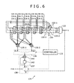
- FIG. 6 shows an arrangement of an encoding apparatus 121 according to an embodiment of the present invention.
- the encoding apparatus 121 encodes input data (information bits) into an IRA-type quasi-cyclic code according to the parity-check matrix H QCIRA1 shown in FIG. 5, and outputs the encoded data as code bits. It is assumed that information bits corresponding to ith rows (1 ⁇ i ⁇ 15) of the matrixes HI xy in the information part 101 of the parity-check matrix H QCIRA1 are represented by m i and code bits output from the encoding apparatus 121 are represented by c i (1 ⁇ i ⁇ 25).
- the encoding apparatus 121 is supplied with information bits m 1 , m 2 , m 3 , ..., m 15 at respective times t1 through t15.
- the controller 131 sets the switches 133 to terminals P, cyclically shifting the information bits m i stored in the registers 134-1 through 134-15, and sets the switch 138 to a terminal P, outputting parity bits calculated in the encoding apparatus 121 as code bits C 16 , C 17 , C 18 , ..., C 25 to the subsequent stage.
- the controller 131 sets the switch 136 to a terminal Al, supplying a calculated result from an adder 135-1 to an arithmetic unit 141.
- the controller 131 sets the switch 136 to a terminal A2, supplying a calculated result from an adder 135-2 to the arithmetic unit 141.
- a separator 132 separates the serially input information bits m i into k0 parallel sequences (three parallel sequences) of information bits so that information bits m i will be stored in the corresponding registers 134-1 through 134-15, and supplies the separated information bits m i to the switch 133.
- the separator 132 separates the information bits m i into the three parallel sequences so that the information bits m 1 , m 2 , m 3 , m 4 , m 5 will be stored in the respective registers 134-1 through 134-5, the information bits m 6 , m 7 , m 8 , m 9 , m 10 will be stored in the respective registers 134-6 through 134-10, and the information bits m 11 , m 12 , m 13 , m 14 , m 15 will be stored in the respective registers 134-11 through 134-15.
- the switch 133 includes a switch 133-1 connected to the registers 134-1 through 134-5, a switch 133-2 connected to the registers 134-6 through 134-10, and a switch 133-3 connected to the registers 134-11 through 134-15.
- Each of the switches 133-1 through 133-3 have terminals P, D and is set to the terminal P or D at a time by the controller 131.
- the switches 133-1 through 133-3 are set to the terminal D by the controller 131, they store the information bits m i from the separator 132 into the registers 134-1 through 134-15.
- the switches 133-1 through 133-3 are set to the terminal P by the controller 131, they cyclically shift the information bits m i stored in the registers 134-1 through 134-15 through three loops.
- the switch 133-1 when the switch 133-1 is set to the terminal D by the controller 131, it stores the information bits m 1 , m 2 , m 3 , m 4 , m 5 from the separator 132 in the respective registers 134-1 through 134-5, and when the switch 133-1 is set to the terminal P by the controller 131, it cyclically shifts the information bits stored in the registers 134-1 through 134-5 through a loop having the registers 134-1 through 134-5.
- the switch 133-2 When the switch 133-2 is set to the terminal D by the controller 131, it stores the information bits m 6 , m 7 , m 8 , m 9 , m 10 from the separator 132 in the respective registers 134-6 through 134-10, and when the switch 133-2 is set to the terminal P by the controller 131, it cyclically shifts the information bits stored in the registers 134-6 through 134-10 through a loop having the registers 134-6 through 134-10.
- the switch 133-3 When the switch 133-3 is set to the terminal D by the controller 131, it stores the information bits m 11 , m 12 , m 13 , m 14 , m 15 from the separator 132 in the respective registers 134-11 through 134-15, and when the switch 133-3 is set to the terminal P by the controller 131, it cyclically shifts the information bits stored in the registers 134-11 through 134-15 through a loop having the registers 134-11 through 134-15.
- the registers 134-1 through 134-15 include as many shift registers as the number of input information bits, and store the information bits m i input thereto.
- the registers 134-1 through 134-15 are divided into groups to provide k0 (i.e., three) loops, i.e., groups each having m (i.e., five) registers, i.e., groups having registers 134-1 through 134-5, registers 134-6 through 134-10, and registers 134-11 through 134-15, respectively.
- the adders 135-1, 135-2 are supplied with values depending on the nonzero elements in the rows of the information part 101 of the parity-check matrix H QCIRA1 .
- the adder 135-1 is supplied with the seven values from the registers 134-1, 134-2, 134-6, 134-8, 134-11, 134-12, 134-13 as the values depending on the nonzero elements in the rows of the upper block (HI 1y (1 ⁇ y ⁇ 3) of the information part 101 of the parity-check matrix H QCIRA1
- the adder 135-2 is supplied with the six values from the registers 134-1, 134-3, 134-4, 134-7, 134-8, 134-12 as the values depending on the nonzero elements in the rows of the lower block (HI 2y (1 ⁇ y ⁇ 3) of the information part 101 of the parity-check matrix H QCIRA1 ,
- the adders 135-1, 135-2 calculates the sum on F 2 of the supplied values.
- the switch 136 has the terminal Al connected to the adder 135-1 and the terminal A2 connected to the adder 135-2.
- the switch 136 is controlled by the controller 131 to supply the accumulator 137 with the sum on F 2 of the values depending on the nonzero elements in the rows of the information part 101 as the calculated sum from the adder 135 that is connected to the selected terminal of the switch 136.
- the accumulator 137 includes an arithmetic unit 141 and a register 142.
- the arithmetic unit 141 calculates the sum on F 2 of the calculated sum from the switch 136 and the parity bit determined in the immediately previous cycle and stored in the register 142 to determine parity bits of IRA-type quasi-cycle codes, and supplies the determined parity bits to the register 142.
- the register 142 includes a shift register, for example, and stores the parity bits from the arithmetic unit 141, supplies the stored parity bits to the arithmetic unit 141, and also outputs the stored parity bits as code bits c 16 , c 17 , c 18 , ..., c 25 through the switch 138 with the terminal P selected to the subsequent stage.
- the switch 138 When the switch 138 is set to the terminal P by the controller 131, the switch 138 outputs the input information bits m i as code bits c i to the subsequent stage. When the switch 138 is set to the terminal D by the controller 131, the switch 138 outputs the parity bits from the accumulator 137 directly as code bits c i to the subsequent stage.
- the switch 133-1 when the switch 133-1 is set to the terminal D, the information bits m 1 , m 2 , m 3 , m 4 , m 5 from the separator 132 are stored successively in the respective registers 134-1 through 134-5, and when the switch 133-2 is set to the terminal D, the information bits m 6 , m 7 , m 8 , m 9 , m 10 from the separator 132 are stored successively in the respective registers 134-6 through 134-10, and when the switch 133-3 is set to the terminal D, the information bits m 11 , m 12 , m 13 , m 14 , m 15 from the separator 132 are stored successively in the respective registers 134-11 through 134-15.
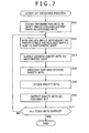
- step S12 the controller 131 sets the switches 133, 138 to the terminals P and sets the switch 136 depending on the parity-check matrix H QCIRA1 in step S12, after which control goes to step S13.
- the adders 135 are supplied with values depending on the parity-check matrix H QCIRA1 , and calculate the sum on F 2 of the supplied values, i.e., exclusive-OR the supplied values, and supply the calculated sum to the arithmetic unit 141.
- step S12 the controller 131 starts cyclically shifting the information bits m i stored in the registers 134-1 through 134-15.
- the switch 133-1 is set to the terminal P
- the information bits m 1 , m 2 , m 3 , m 4 , m 5 stored in the registers 134-1 through 134-5 start being cyclically shifted through the loop having the registers 134-1 through 134-5.
- the switch 133-2 is set to the terminal P, the information bits m 6 , m 7 , m 8 , m 9 , m 10 stored in the registers 134-6 through 134-10 start being cyclically shifted through the loop having the registers 134-6 through 134-10.
- the switch 133-2 When the switch 133-2 is set to the terminal P, the information bits m 11 , m 12 , m 13 , m 14 , m 15 stored in the registers 134-11 through 134-15 start being cyclically shifted through the loop having the registers 134-11 through 134-15.
- the adders 135 are supplied with values depending on the parity-check matrix H QCIRA1 , i.e., values depending on the nonzero elements in the rows of the information part 101 of the parity-check matrix H QCIRA1 .
- the adder 135-1 is supplied with the seven information values (information bits) stored in the registers 134-1, 134-2, 134-6, 134-8, 134-11, 134-12, 134-13, and the adder 135-2 is supplied with the six information values stored in the registers 134-1, 134-3, 134-4, 134-7, 134-8, 134-12.
- the controller 131 sets the switch 136 to the terminal Al depending on the rows of the information part 101 of the parity-check matrix H QCIRA1 , supplying the calculated sum from the adder 135-1 to the arithmetic unit 141.
- the controller 131 sets the switch 136 to the terminal A2 depending on the rows of the information part 101 of the parity-check matrix H QCIRA1 , supplying the calculated sum from the adder 135-2 to the arithmetic unit 141.
- the values (m 1 , m 2 , m 6 , m 8 , m 11 , m 12 , m 13 ) corresponding to the first row of the information part 101 of the parity-check matrix H QCIRA1 are supplied to the adder 135-1, which calculates the sum on F 2 of the supplied values corresponding to the first row of the information part 101 of the parity-check matrix H QCIRA1 .
- the switch 136 since the switch 136 is set to the terminal Al, the calculated sum for the first row from the adder 135-1, i.e., the sum on F 2 of the values depending on the nonzero elements in the first row of the information part 101 of the parity-check matrix H QCIRA1 , is supplied through the switch 136 to the arithmetic unit 141.
- the values (m 2 , m 3 , m 7 , m 9 , m 12 , m 13 , m 14 ) corresponding to the second row of the information part 101 of the parity-check matrix H QCIRA1 are supplied to the adder 135-1, which calculates the sum on F 2 of the supplied values corresponding to the second row of the information part 101 of the parity-check matrix H QCIRA1 .
- the switch 136 since the switch 136 is set to the terminal Al, the calculated sum for the second row from the adder 135-1 is supplied through the switch 136 to the arithmetic unit 141.
- the adder 135-1 calculates the sum on F 2 of the supplied values corresponding to the row to be processed of the information part 101 of the parity-check matrix H QCIRA1 , and supplies the calculated sum to the arithmetic unit 141.
- the values (m 1 , m 3 , m 4 , m 7 , me, m 12 ) corresponding to the sixth row of the information part 101 of the parity-check matrix H QCIRA1 are supplied to the adder 135-2, which calculates the sum on F 2 of the supplied values corresponding to the sixth row of the information part 101 of the parity-check matrix H QCIRA1 .
- the switch 136 since the switch 136 is set to the terminal A2, the calculated sum for the sixth row from the adder 135-2 is supplied through the switch 136 to the arithmetic unit 141.
- the values (m 2 , m 4 , m 5 , m 8 , m 9 , m 13 ) corresponding to the seventh row of the information part 101 of the parity-check matrix H QCIRA1 are supplied to the adder 135-2, which calculates the sum on F 2 of the supplied values corresponding to the seventh row of the information part 101 of the parity-check matrix H QCIRA1 .
- the switch 136 since the switch 136 is set to the terminal A2, the calculated sum for the seventh row from the adder 135-2 is supplied through the switch 136 to the arithmetic unit 141.
- the adder 135-2 calculates the sum on F 2 of the supplied values corresponding to the row to be processed of the information part 101 of the parity-check matrix H QCIRA1 , and supplies the calculated sum to the arithmetic unit 141 through the switch 136.
- the adder 135-1 or 135-2 supplies the sum on F 2 of the values corresponding to the nonzero elements in the rows of the information part 101 of the parity-check matrix H QCIRA1 of the information part 101 to the arithmetic unit 141. Then, control goes from step S12 to step S13.
- step S13 the register 142 supplies the parity bits stored in step S15, to be described later on, to the arithmetic unit 141. Then, control goes to step S14.
- step S14 when the encoding process is started, an initial value of "0" is stored in the register 142. Therefore, when step S13 is executed for the first time, the register 142 supplies "0" to the arithmetic unit 141.
- step S14 the arithmetic unit 141 calculates the sum on F 2 of the calculated result for the row to be processed of the information part 101 of the parity-check matrix H QCIRA3 , which is supplied from the adder 135-1 or 135-2, and the parity bits stored in the register 142, determining new parity bits, and supplies the determined parity bits to the register 142. Then, control goes to step S15.
- step S15 the register 142 stores the supplied parity bits.
- step S16 in which the register 142 outputs the supplied parity bits through the switch 138 with the terminal P selected as code bits c i to the subsequent stage. Thereafter, control goes to step S17.
- step S17 the controller 131 determines whether the time t25 is reached based on the clock incorporated therein and all code bits c i have been output or not. If the controller 131 judges that the time t25 is not reached and all code bits c i have not been output, then control goes back to step S12, and the processing from step S12 is repeated. If the controller 131 judges in step S17 that the time t25 is reached and all code bits c i have been output, then the encoding process is put to an end.
- the code bits are output in the order of code bits C 16 , C 17 , C 18 , C 19 , C 20 , C 21 , C 22 , C 23 , C 24 , C 25 to the subsequent stage.
- the encoding apparatus 121 finally determines 10 parity bits, and combines the 15 information bits and the 10 parity bits, thereby generating a 25-bit IRA-type quasi-cyclic code.
- the encoding apparatus 121 thus encodes information into an IRA-type quasi-cyclic code, using the parity-check matrix H QCIRA1 .
- the information part 101 of the parity-check matrix H QCIRA1 is represented by quasi-cyclic matrixes, and the sum of the values corresponding to the nonzero elements in the rows of the information part 101 of the parity-check matrix H QCIRA1 is simply determined using shift registers, new parity bits can be determined by calculating the sum on F 2 of, i.e., exclusive-ORing, the determined sum of the values corresponding to the nonzero elements in the rows and the parity bits determined in the immediately previous cycle.
- the encoding apparatus 121 does not employ an expensive random interleaver, but is of a less costly and simple arrangement as it employs simple shift registers.
- FIG. 8 shows another parity-check matrix H QCIRA2 for encoding data into IRA-type quasi-cyclic codes according to an embodiment of the present invention.
- the parity-check matrix H QCIRA2 shown in FIG. 8 is another example of the parity-check matrix H QCIRA1 shown in FIG. 5, will not be described in detail to avoid a repetitive description.
- the parity-check matrix H QCIRA2 has 10 (rows) x 25 (columns) elements.
- the parity-check matrix H QCIRA2 includes an information part 201 having elements represented by the information length k (15) and a parity part 202 having elements represented by code length n - information length k (10).
- the information part 201 includes a 2 (rows) x 3 (columns) quasi-cyclic matrix having, as elements, a matrix HI 11 , a matrix HI 12 , a matrix HI 13 , a matrix HI 21 , a matrix HI 22 , and a matrix HI 23 (matrixes HI xy (1 ⁇ x ⁇ 2), (1 ⁇ y ⁇ 3), each being a cyclic square matrix having 5 (rows) x 5 (columns) elements.
- the matrix HI 11 of the information part 201 is a 5 x 5 cyclic square matrix made up of a first row of "ab000”, a second row of "0ab00", a third row of "00ab0”, a fourth row of "000ab”, and a fifth row of "b000a”.
- the matrix HI 12 of the information part 201 is a 5 x 5 cyclic square matrix made up of a first row of "c0d00", a second row of "0c0d0", a third row of "00c0d”, a fourth row of "d00c0", and a fifth row of "0d0c”.
- the matrix HI 13 of the information part 201 is a 5 x 5 cyclic square matrix made up of a first row of "efg00", a second row of "0efg0", a third row of "00efg", a fourth row of "g00ef", and a fifth row of "fg00e”.
- the matrix HI 21 of the information part 201 is a 5 x 5 cyclic square matrix made up of a first row of "j0op0", a second row of "0j0op", a third row of "p0j0o”, a fourth row of "op0j0”, and a fifth row of "0op0j”.
- the matrix HI 22 of the information part 201 is a 5 x 5 cyclic square matrix made up of a first row of "0rs00", a second row of "00rs0", a third row of "000rs", a fourth row of "s000r”, and a fifth row of "rs000".
- each of the horizontal arrays of the rows in the upper block (matrixes HI 1y (1 ⁇ y ⁇ 3)) of the information part 201 is made up of seven nonzero elements and eight zero elements "0", and each row of each of the matrixes HI 1y is produced by shifting, to the right, the values of the immediately above row by one position.
- Each of the horizontal arrays of the rows in the lower block (matrixes HI 2y (1 ⁇ y ⁇ 3)) of the information part 201 is made up of six nonzero elements and nine zero elements "0", and each row of each of the matrixes HI 2y is produced by shifting, to the right, the values of the immediately above row by one position. Stated otherwise, the values of each row of each of the matrixes HI xy of the information part 201 are produced by cyclically shifting the values of the immediately above row.
- the parity part 202 includes a matrix HP which is a 10 (rows) x 10 (columns) square matrix having nonzero elements ("h" and "i” in FIG. 8) arranged in a step-like pattern and zero elements ("0") placed as remaining entries.
- HP which is a 10 (rows) x 10 (columns) square matrix having nonzero elements ("h" and "i” in FIG. 8) arranged in a step-like pattern and zero elements ("0") placed as remaining entries.
- the matrix HP of the parity part 202 includes a 10 x 10 square matrix having a first row of "h000000000”, a second row of "ih00000000”, a third row of "0ih0000000”, a fourth row of "00ih000000”, a fifth row of "000ih00000”, a sixth row of "0000ih0000", a seventh row of "00000ih000”, an eighth row of "000000ih00", a ninth row of "0000000ih0", and a tenth row of "00000000ih”.
- each row is produced by shifting, to the right, "h” and "i” of the immediately above row by one position, and has a step-like structure, except that the first row has only one h.
- the parity-check matrix H QCIRA2 for IRA-type quasi-cyclic codes has the information part 201 made up of zero elements and nonzero elements arranged in an arbitrary pattern and the parity part 202 having nonzero elements arranged in a step-like pattern and zero elements placed as remaining entries, as with a parity-check matrix for IRA codes.
- the information part 201 of the parity-check matrix H QCIRA2 has cyclic matrixes as elements, as with a parity-check matrix for quasi-cyclic codes.
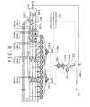
- FIG. 9 shows in block form an encoding apparatus 221 for encoding data into IRA-type quasi-cyclic codes according to the present invention.
- the encoding apparatus 221 shown in FIG. 9 is essentially of the same arrangement as the encoding apparatus 121 shown in FIG. 6 except that multipliers 231-1 through 231-13 and a multiplier 232 are added, and an accumulator 233 is added instead of the accumulator 137. Therefore, the encoding apparatus 221 will not be described in detail below to avoid a repetitive description.
- the encoding apparatus 221 shown in FIG. 9 encodes input data (information symbols) into an IRA-type quasi-cyclic code according to the parity-check matrix H QCIRA2 shown in FIG. 8, and outputs the encoded data as code symbols. It is assumed that information symbols corresponding to uth rows (1 ⁇ u ⁇ 15) of the matrixes HI xy in the information part 201 of the parity-check matrix H QCIRA2 are represented by m u and code symbols output from the encoding apparatus 221 are represented by C u (1 ⁇ u ⁇ 25). The encoding apparatus 221 is supplied with information symbols m 1 , m 2 , m 3 , ..., m 15 at respective times t1 through t15.
- a controller 131 performs a timing process based on a clock incorporated therein, and sets (changes) switches 133, 136, and 138 to terminals according to the parity-check matrix H QCIRA2 .
- a separator 132 separates the serially input information symbols m u into three parallel sequences of information symbols so that information symbols m u will be stored in the corresponding registers 134-1 through 134-15, and supplies the separated information symbols m u to the switch 133.
- the switches 133-1 through 133-3 When the switches 133-1 through 133-3 are set to the terminals D by the controller 131, they store the information symbols m u from the separator 132 into the respective registers 134-1 through 134-15, and when the switches 133-1 through 133-3 are set to the terminals P by the controller 131, they cyclically shift the information symbols m u stored in the registers 134-1 through 134-15 through the three loops.
- the registers 134-1 through 134-15 include shift registers, and store the information symbols m u input thereto.
- the registers 134-1 through 134-15 are divided into groups to provide three loops, i.e., groups having registers 134-1 through 134-5, registers 134-6 through 134-10, and registers 134-11 through 134-15, respectively.
- the adders 135-1, 135-2 are connected to the registers 134-1 through 134-15 through the multipliers 231-1 through 231-13 such that the adders 135-1, 135-2 are supplied with the values depending on the nonzero elements in the rows of the information part 201 of the parity-check matrix H QCIRA2 .
- the number of the multipliers 231-1 through 231-13 is determined by the number of nonzero elements in the information part 201.
- the multiplier 231-1 is connected between the register 134-1 and the adder 135-1, and multiplies the information symbol m u from the register 134-1 by "a”.
- the multiplier 231-2 is connected between the register 134-6 and the adder 135-1, and multiplies the information symbol m u from the register 134-6 by "c”.
- the multiplier 231-3 is connected between the register 134-11 and the adder 135-1, and multiplies the information symbol m u from the register 134-11 by "e”.
- the multiplier 231-4 is connected between the register 134-1 and the adder 135-2, and multiplies the information symbol m u from the register 134-11 by "j”.
- the multiplier 231-5 is connected between the register 134-2 and the adder 135-1, and multiplies the information symbol m u from the register 134-2 by "b".
- the multiplier 231-6 is connected between the register 134-12 and the adder 135-1, and multiplies the information symbol m u from the register 134-12 by "f”.
- the multiplier 231-7 is connected between the register 134-7 and the adder 135-2, and multiplies the information symbol m u from the register 134-7 by "r".
- the multiplier 231-8 is connected between the register 134-12 and the adder 135-2, and multiplies the information symbol m u from the register 134-12 by "t”.
- the multiplier 231-9 is connected between the register 134-8 and the adder 135-1, and multiplies the information symbol m u from the register 134-8 by "d”.
- the multiplier 231-10 is connected between the register 134-13 and the adder 135-1, and multiplies the information symbol m u from the register 134-13 by "g”.
- the multiplier 231-11 is connected between the register 134-3 and the adder 135-2, and multiplies the information symbol m u from the register 134-3 by "o".
- the multiplier 231-12 is connected between the register 134-8 and the adder 135-2, and multiplies the information symbol m u from the register 134-8 by "s".
- the multiplier 231-13 is connected between the register 134-4 and the adder 135-2, and multiplies the information symbol m u from the register 134-4 by "p”.
- the adder 135-1 is supplied with, as the values depending on the nonzero elements in the rows of the upper block (HI 1y (1 ⁇ y ⁇ 3)) of the information part 201 of the parity-check matrix H QCIRA2 , the information symbol m u from the register 134-1 as multiplied by "a” by the multiplier 231-1, the information symbol m u from the register 134-2 as multiplied by "b” by the multiplier 231-5, the information symbol m u from the register 134-6 as multiplied by "c” by the multiplier 231-2, the information symbol m u from the register 134-8 as multiplied by "d” by the multiplier 231-9, the information symbol m u from the register 134-11 as multiplied by "e” by the multiplier 231-3, the information symbol m u from the register 134-12 as multiplied by "f” by the multiplier 231-6, and the information symbol m u from the register 134-13 as multiplied by "g"
- the adder 135-2 is supplied with, as the values depending on the nonzero elements in the rows of the lower block (HI 2y (1 ⁇ y ⁇ 3)) of the information part 201 of the parity-check matrix H QCIRA2 , the information symbol m u from the register 134-1 as multiplied by "j" by the multiplier 231-4, the information symbol m u from the register 134-3 as multiplied by "o” by the multiplier 231-11, the information symbol m u from the register 134-4 as multiplied by "p” by the multiplier 231-13, the information symbol m u from the register 134-7 as multiplied by "r” by the multiplier 231-7, the information symbol m u from the register 134-8 as multiplied by "s” by the multiplier 231-12, and the information symbol m u from the register 134-12 as multiplied by "t” by the multiplier 231-8.
- the adders 135-1, 135-2 calculates the sum on Fq of the supplied values.
- the switch 136 has the terminal Al connected to the adder 135-1 and the terminal A2 connected to the adder 135-2.
- the switch 136 is controlled by the controller 131 to supply the accumulator 233 with the sum on F 2 of the values depending on the nonzero elements in the rows as the calculated sum from the adder 135 that is connected to the selected terminal of the switch 136.
- the multiplier 232 is connected between the switch 136 and the accumulator 233, and multiplies the parity bits from the switch 136 by "- h -1 " and supplies the product to the accumulator 233.
- the accumulator 233 includes an arithmetic unit 141, a register 142, and a multiplier 241.
- the arithmetic unit 141 calculates the sum on Fq of the product from the multiplier 232 and the parity symbols from the register 142 as multiplied by "i" by the multiplier 241, thereby determining new parity symbols, and supplies the determined parity symbols to the register 142.
- the register 142 includes a shift register, for example, and stores the parity symbols from the arithmetic unit 141, supplies the stored parity symbols to the arithmetic unit 141 through the multiplier 241, and also outputs the stored parity symbols as code symbols C 16 , C 17 , C 18 , ..., C 25 through the switch 138 with the terminal P selected to the subsequent stage.
- the multiplier 241 multiplies the parity symbols from the register 142 by "i", and supplies the product to the arithmetic unit 141.
- the switch 138 When the switch 138 is set to the terminal D by the controller 131, the switch 138 outputs the input information symbols m u as code symbols c u to the subsequent stage. When the switch 138 is set to the terminal P by the controller 131, the switch 138 outputs the parity symbols from the accumulator 233 directly as code symbols c u to the subsequent stage.
- Steps S31 and S35 through S38 shown in FIG. 10 are identical to steps S11 and S14 through S17 shown in FIG. 7, and will not be described in detail below to avoid a repetitive description.
- step S32 the controller 131 sets the switches 133, 138 to the terminals P and sets the switch 136 depending on the parity-check matrix H QCIRA2 in step S32, after which control goes to step S33.
- the adders 135 are supplied with values depending on the parity-check matrix H QCIRA2 , and calculate the sum on F 2 of the supplied values, and supply the calculated sum to the multiplier 232.
- step S32 The processing of step S32 will be described in greater detail below.
- the controller 131 starts cyclically shifting the information symbols m u stored in the registers 134-1 through 134-15.
- the switch 133-1 is set to the terminal P, the information symbols stored in the registers 134-1 through 134-15 start being cyclically shifted through the three loops, as described above with reference to FIG. 7.
- the adders 135-1, 135-2 are connected to the registers 134-1 through 134-15 through the multipliers 231-1 through 231-13 such that the adders 135-1, 135-2 are supplied with the values depending on the nonzero elements in the rows of the information part 201 of the parity-check matrix H QCIRA2 .
- the adder 135-1 is supplied with, as the values depending on the nonzero elements in the rows of the upper block (HI 1y (1 ⁇ y ⁇ 3)) of the information part 201 of the parity-check matrix H QCIRA2 , the information symbol m u from the register 134-1 as multiplied by "a” by the multiplier 231-1, the information symbol m u from the register 134-2 as multiplied by "b” by the multiplier 231-5, the information symbol m u from the register 134-6 as multiplied by "c” by the multiplier 231-2, the information symbol m u from the register 134-8 as multiplied by "d” by the multiplier 231-9, the information symbol m u from the register 134-11 as multiplied by "e” by the multiplier 231-3, the information symbol m u from the register 134-12 as multiplied by "f” by the multiplier 231-6, and the information symbol m u u
- the adder 135-2 is supplied with, as the values depending on the nonzero elements in the rows of the lower block (HI 2y (1 ⁇ y ⁇ 3)) of the information part 201 of the parity-check matrix H QCIRA2 , the information symbol m u from the register 134-1 as multiplied by "j" by the multiplier 231-4, the information symbol m u from the register 134-3 as multiplied by "o” by the multiplier 231-11, the information symbol m u from the register 134-4 as multiplied by "p” by the multiplier 231-13, the information symbol m u from the register 134-7 as multiplied by "r” by the multiplier 231-7, the information symbol m u from the register 134-8 as multiplied by "s” by the multiplier 231-12, and the information symbol m u from the register 134-12 as multiplied by "t” by the multiplier 231-8.
- the controller 131 sets the switch 136 to the terminal Al at the times t16 through t20, supplying the calculated sum from the adder 135-1 to the multiplier 232, and sets the switch 136 to the terminal A2 at the times t21 through t25, supplying the calculated sum from the adder 135-2 to the multiplier 232.
- the values (a ⁇ m 1 , b ⁇ m 2 , c ⁇ m 6 , d ⁇ m 8 , e ⁇ m 11 , f ⁇ m 12 , g ⁇ m 13 ) corresponding to the first row of the information part 201 of the parity-check matrix H QCIRA2 are supplied to the adder 135-1, which calculates the sum on Fq of the supplied values corresponding to the first row of the information part 201 of the parity-check matrix H QCIRA2 .
- the switch 136 since the switch 136 is set to the terminal Al, the calculated sum from the adder 135-1, i.e., the sum on F 2 of the values depending on the nonzero elements in the first row of the information part 201 of the parity-check matrix H QCIRA2 , is supplied through the switch 136 to the multiplier 232.
- the values (a ⁇ m 2 , b ⁇ m 3 , c ⁇ m 7 , d ⁇ m 9 , e ⁇ m 12 , f ⁇ m 13 , g ⁇ m 14 ) corresponding to the second row of the information part 201 of the parity-check matrix H QCIRA2 are supplied to the adder 135-1, which calculates the sum on Fq of the supplied values corresponding to the second row of the information part 201 of the parity-check matrix H QCIRA2 .
- the switch 136 since the switch 136 is set to the terminal Al, the calculated sum for the second row from the adder 135-1 is supplied through the switch 136 to the multiplier 232.
- the adder 135-1 calculates the sum on Fq of the supplied values corresponding to the row to be processed of the information part 201 of the parity-check matrix H QCIRA2 , and supplies the calculated sum through the switch 136 to the multiplier 232.
- the values (j ⁇ m 1 , o ⁇ m 3 , p ⁇ m 4 , r ⁇ m 7 , s ⁇ m 8 , t ⁇ m 12 ) corresponding to the sixth row of the information part 201 of the parity-check matrix H QCIRA2 are supplied to the adder 135-2, which calculates the sum on Fq of the supplied values corresponding to the sixth row of the information part 201 of the parity-check matrix H QCIRA2 .
- the switch 136 since the switch 136 is set to the terminal A2, the calculated sum for the sixth row from the adder 135-2 is supplied through the switch 136 to the multiplier 232.
- the values (j ⁇ m 2 , o, m 4 , p ⁇ m 5 , r ⁇ m 8 , s ⁇ m 9 , t ⁇ m 13 ) corresponding to the seventh row of the information part 201 of the parity-check matrix H QCIRA2 are supplied to the adder 135-2, which calculates the sum on Fq of the supplied values corresponding to the seventh row of the information part 201 of the parity-check matrix H QCIRA2 .
- the switch 136 since the switch 136 is set to the terminal A2, the calculated sum for the seventh row from the adder 135-2 is supplied through the switch 136 to the multiplier 232.
- the adder 135-2 calculates the sum on F q of the supplied values corresponding to the row to be processed of the information part 201 of the parity-check matrix H QCIRA2 , and supplies the calculated sum through the switch 136 to the multiplier 232.
- step S32 the sum of the values corresponding to the row to be processed of the information part 201 of the parity-check matrix H QCIRA2 is supplied from the adder 135-1 or 135-2 to the multiplier 232. Control then goes to step S33.
- step S34 the register 142 supplies the parity symbols stored therein in step S36, to described later on, to the multiplier 241, which multiplies the parity symbols by "i".
- the parity symbols as multiplied by "i” are supplied to the arithmetic unit 141. Thereafter, control goes to step S35.
- step S35 the arithmetic unit 141 calculates the sum on F q of the parity symbols as multiplied by "- h -1 " for the row to be processed and the parity symbols multiplied by "i" by the multiplier 241, determining new parity symbols.
- the arithmetic unit 141 supplies the determined parity symbols to the register 142.
- step S36 the register 142 stores the supplied parity symbols.
- step S37 in which the register 142 outputs the supplied parity symbols through the switch 138 with the terminal P selected as code symbols c u to the subsequent stage. Thereafter, control goes to step S38.
- step S38 the controller 131 determines whether the time 125 is reached based on the clock incorporated therein and all code symbols C u have been output or not. If the controller 131 judges that the time t25 is not reached and all code symbols C u have not been output, then control goes back to step S32, and the processing from step S32 is repeated. If the controller 131 judges in step S38 that the time t25 is reached and all code symbols C u have been output, then the encoding process is put to an end.
- the code symbols are output in the order of code symbols C 16 , C 17 , C 18 , C 19 , C 20 , C 21 , C 22 , C 23 , C 24 , C 25 to the subsequent stage.
- the encoding apparatus 221 finally determines 10 parity symbols, and combines the 15 information symbols and the 10 parity symbols, thereby generating a 25-symbol IRA-type quasi-cyclic code.
- the encoding apparatus 221 thus encodes information into an IRA-type quasi-cyclic code, using the parity-check matrix H QCIRA2 .
- the encoding apparatus 221 does not employ an expensive random interleaver, but is of a less costly and simple arrangement as it employs simple shift registers.
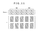
- FIG. 11 shows still another parity-check matrix H QCIRA3 for encoding data into IRA-type quasi-cyclic codes according to the present invention.
- the parity-check matrix H QCIRA3 shown in FIG. 11 is another example of the parity-check matrix H QCIRA2 shown in FIG. 8, will not be described in detail to avoid a repetitive description.
- the parity-check matrix H QCIRA3 has 10 (rows) x 25 (columns) elements.
- the parity-check matrix H QCIRA3 includes an information part 301 having elements represented by the information length k (15) and a parity part 302 having elements represented by code length n - information length k (10).
- the information part 301 is of an arrangement identical to the information part 201 of the parity-check matrix H QCIRA2 shown in FIG. 8.
- the information part 301 includes a 2 (rows) x 3 (columns) quasi-cyclic matrix having, as elements, a matrix HI 11 , a matrix HI 12 , a matrix HI 13 , a matrix HI 21 , a matrix HI 22 , and a matrix HI 23 (matrixes HI xy (1 ⁇ x ⁇ 2) , (1 ⁇ y ⁇ 3), each being a cyclic square matrix having 5 (rows) x 5 (columns) elements.
- each of the horizontal arrays of the rows in the upper block (matrixes HI 1y (1 ⁇ y ⁇ 3)) of the information part 301 is made up of seven nonzero elements and eight zero elements "0", and each row of each of the matrixes HI 1y is produced by shifting, to the right, the values of the immediately above row by one position.
- Each of the horizontal arrays of the rows in the lower block (matrixes HI 2y (1 ⁇ y ⁇ 3)) of the information part 301 is made up of six nonzero elements and nine zero elements "0", and each row of each of the matrixes HI 2y is produced by shifting, to the right, the values of the immediately above row by one position. Stated otherwise, the values of each row of each of the matrixes HI xy of the information part 301 are produced by cyclically shifting the values of the immediately above row.
- the matrix HP 11 of the parity part 302 includes a 5 x 5 cyclic square matrix having a first row of "h0000", a second row of "0h000", a third row of "00h00", a fourth row of "000h0", and a fifth row of "0000h”.
- the matrix HP 12 of the parity part 302 includes a 5 x 5 square matrix having a first row of "00000”, a second row of "i0000", a third row of "0i000”, a fourth row of "00i00", and a fifth row of "000i0".
- the matrix HP 21 of the parity part 302 includes a 5 x 5 cyclic square matrix having a first row of "i0000", a second row of "0i000”, a third row of "00i00", a fourth row of "000i0", and a fifth row of "0000i”.
- the matrix HP 22 of the parity part 302 includes a 5 x 5 cyclic square matrix having a first row of "z0000", a second row of "0z000”, a third row of "00z00”, a fourth row of "000z0", and a fifth row of "0000z".
- each row is produced by shifting, to the right, the values of the immediately above row by one position. That is, the values of each row in each of the matrixes HP of the parity part 302 are produced by cyclically shifting the values of the immediately above row.
- the parity-check matrix H QCIRA3 for IRA-type quasi-cyclic codes has the information part 301 made up of zero elements and nonzero elements arranged in an arbitrary pattern and the parity part 302 having nonzero elements arranged in a step-like pattern and zero elements placed as remaining entries, as with a parity-check matrix for IRA codes.
- the information part 301 of the parity-check matrix H QCIRA3 has cyclic matrixes as elements, as with a parity-check matrix for quasi-cyclic codes, and the parity part 302 of the parity-check matrix H QCIRA3 is arranged so as to be cyclic.
- FIG. 12 shows in block form an encoding apparatus 321 for encoding data into IRA-type quasi-cyclic codes according to the present invention.
- the encoding apparatus 321 shown in FIG. 12 is essentially of the same arrangement as the encoding apparatus 221 shown in FIG. 9 except that the multiplier 232 is dispensed with and multipliers 331-1 and 331-2 are added. Therefore, the encoding apparatus 321 will not be described in detail below to avoid a repetitive description.
- the encoding apparatus 321 shown in FIG. 12 encodes input data (information symbols) into an IRA-type quasi-cyclic code according to the parity-check matrix H QCIRA3 shown in FIG. 11, and outputs the encoded data as code symbols. It is assumed that information symbols corresponding to uth rows (1 ⁇ u ⁇ 15) of the matrixes HI xy in the information part 301 of the parity-check matrix H QCIRA3 are represented by m u and code symbols output from the encoding apparatus 321 are represented by C u (1 ⁇ u ⁇ 25). The encoding apparatus 321 is supplied with information symbols m 1 , m 2 , m 3 , ..., m 15 at respective times t1 through t15.
- a controller 131 performs a timing process based on a clock incorporated therein, and sets (changes) switches 133, 136, and 138 to terminals according to the parity-check matrix H QCIRA3 . Specifically, at the times t1 through t15, the controller 131 sets the switch 133 to terminals D, storing the supplied information symbols m u in the registers 134-1 through 134-15, and sets the switch 138 to the terminal D, outputting the supplied information symbols m u directly as code symbols c u to the subsequent stage.
- the controller 131 sets the switch 133 to terminals P, cyclically shifting the information symbols m u stored in the registers 134-1 through 134-15, and sets the switch 138 to a terminal P, outputting parity symbols calculated in the encoding apparatus 321 as code symbols C u to the subsequent stage.
- the controller 131 sets the switch 136 to the terminal Al, supplying a calculated result from an adder 135-1 to an arithmetic unit 141.
- the controller 131 sets the switch 136 to a terminal A2, supplying a calculated result from an adder 135-2 to the arithmetic unit 141.
- the code symbols are thus output in the order of code symbols C 16 , C 21 , C 17 , C 22 , C 18 , C 23 , C 19 , C 24 , C 20 , C 25 to the subsequent stage.
- a separator 132 separates the serially input information symbols m u into three parallel sequences of information symbols so that information symbols m u will be stored in the corresponding registers 134-1 through 134-15, and supplies the separated information symbols m u to the switch 133.
- switches 133-1 through 133-3 When the switches 133-1 through 133-3 are set to the terminals D by the controller 131, they store the information symbols m u from the separator 132 into the respective registers 134-1 through 134-15, and when the switches 133-1 through 133-3 are set to the terminals P by the controller 131, they cyclically shift the information symbols m u stored in the registers 134-1 through 134-15 through the three loops.
- the registers 134-1 through 134-15 include shift registers, and store the information symbols m u input thereto.
- the registers 134-1 through 134-15 are divided into groups to provide three loops each having five registers, i.e., groups having registers 134-1 through 134-5, registers 134-6 through 134-10, and registers 134-11 through 134-15, respectively.
- the adders 135-1, 135-2 are connected to the registers 134-1 through 134-15 through the multipliers 231-1 through 231-13 such that the adders 135-1, 135-2 are supplied with the values depending on the nonzero elements in the rows of the information part 301 of the parity-check matrix H QCIRA3 .
- the number of the multipliers 231-1 through 231-13 is determined by the number of nonzero elements in the upper and lower blocks of the information part 301.
- the adders 135-1, 135-2 calculates the sum on F q of the supplied values.
- the multiplier 331-1 is connected between the adder 135-1 and the switch 136, and multiplies the calculated sum from the adder 135-1 by "- h -1 ".
- the multiplier 331-2 is connected between the adder 135-2 and the switch 136, and multiplies the calculated sum from the adder 135-2 by "-z -1 ".
- the multipliers 331-1, 331-2 will also be referred to as multipliers 331 if they do not need to be individually separated.
- the switch 136 has the terminal Al connected to the multiplier 331-1 and the terminal A2 connected to the multiplier 331-2.
- the switch 136 is controlled by the controller 131 to supply the accumulator 233 with the calculated result for the rows as multiplied by the multiplier 331 that is connected to the selected terminal of the switch 136. Specifically, when the switch 136 is connected to the terminal Al, the switch 136 outputs the calculated result for the rows as multiplied by "- h -1 " by the multiplier 331-1 to the accumulator 233, and when the switch 136 is connected to the terminal A2, the switch 136 outputs the calculated result for the rows as multiplied by "- z -1 " by the multiplier 331-2 to the accumulator 233.
- the accumulator 233 includes an arithmetic unit 141, a register 142, and a multiplier 241.
- the arithmetic unit 141 calculates the sum on Fq of the product from the switch 136 and the parity symbols from the register 142 as multiplied by "i" by the multiplier 241, thereby determining new parity symbols, and supplies the determined parity symbols to the register 142.
- Steps S51 and S54 through S58 shown in FIG. 13 are identical to steps S31 and S34 through S38 shown in FIG. 10, and will not be described in detail below to avoid a repetitive description.
- step S52 the controller 131 sets the switches 133, 138 to the terminals P in step S52, and sets the switch 136 depending on the parity-check matrix H QCIRA3 in step S53, after which control goes to step S54.
- step S52 the adders 135 are supplied with values depending on the parity-check matrix H QCIRA3 , and calculate the sum on Fq of the supplied values, and supply the calculated sum to one of the multipliers 331.
- step S53 the sum from the adder 135 is multiplied by the multiplier 331, which supplies the product to the arithmetic unit 141.
- the adders 135-1, 135-2 are connected to the registers 134-1 through 134-15 through the multipliers 231-1 through 231-13 such that the adders 135-1, 135-2 are supplied with the values depending on the nonzero elements in the rows of the information part 301 of the parity-check matrix H QCIRA3 .
- the adder 135-1 is supplied with the values depending on the nonzero elements in the rows of the upper block (HI 1y (1 ⁇ y ⁇ 3)) of the information part 301 of the parity-check matrix H QCIRA3 .
- the adder 135-1 calculates the sum on Fq of the supplied values, and supplies the calculated sum to the multiplier 331-1, which multiplies the sum by "- h -1 ".
- the adder 135-2 is supplied with the values depending on the nonzero elements in the rows of the lower block (HI 2b (1 ⁇ b ⁇ 3)) of the information part 301 of the parity-check matrix H QCIRA3 .
- the adder 135-2 calculates the sum on Fq of the supplied values, and supplies the calculated sum to the multiplier 331-2, which multiplies the sum by "- z -1 ".
- the controller 131 sets the switch 136 to the terminal Al, supplying the calculated result, as multiplied by "- h -1 ", from the adder 135-1 to the arithmetic unit 141.
- the controller 131 sets the switch 136 to the terminal A2, supplying the calculated result, as multiplied by "- z -1 ", from the adder 135-2 to the arithmetic unit 141.
- the values (a ⁇ m 1 , b ⁇ m 2 , c ⁇ m 6 , d ⁇ m 8 , e ⁇ m 11 , f ⁇ m 12 , g ⁇ m 13 ) corresponding to the first row of the information part 301 of the parity-check matrix H QCIRA3 are supplied to the adder 135-1, which calculates the sum on Fq of the supplied values corresponding to the first row of the information part 301 of the parity-check matrix H QCIRA3 , and supplies the calculated sum, i.e., the sum on F 2 of the values depending on the nonzero elements in the first row of the information part 301 of the parity-check matrix H QCIRA3 , to the multiplier 331-1.
- the multiplier 331-1 multiplies the sum supplied from the adder 135-1 by "- h -1 ". At this time, since the switch 136 is set to the terminal Al, the calculated result for the first row of the information part 301, as multiplied by "- h -1 " by the multiplier 331-1, is supplied through the switch 136 to the arithmetic unit 141.
- the values (j ⁇ m 1 , o ⁇ m 3 , p ⁇ m 4 , r ⁇ m 7 , s ⁇ m 8 , t ⁇ m 12 ) corresponding to the sixth row of the information part 301 of the parity-check matrix H QCIRA3 are supplied to the adder 135-2, which calculates the sum on Fq of the supplied values corresponding to the sixth row of the information part 301 of the parity-check matrix H QCIRA3 , and supplies the calculated sum to the multiplier 331-2.
- the multiplier 331-2 multiplies the sum supplied from the adder 135-2 by "- z -1 ".
- the values (a ⁇ m 2 , b ⁇ m 3 , c ⁇ m 7 , d ⁇ m 9 , e ⁇ m 12 , f ⁇ m 13 , g ⁇ m 14 ) corresponding to the second row of the information part 301 of the parity-check matrix H QCIRA3 are supplied to the adder 135-1, which calculates the sum on Fq of the supplied values corresponding to the second row of the information part 301 of the parity-check matrix H QCIRA3 , and supplies the calculated sum to the multiplier 331-1.
- the multiplier 331-1 multiplies the sum supplied from the adder 135-1 by "- h -1 ".
- the values (j ⁇ m 2 , o ⁇ m 4 , p ⁇ m 5 , r ⁇ m 8 , s ⁇ m 9 , t ⁇ m 13 ) corresponding to the seventh row of the information part 301 of the parity-check matrix H QCIRA3 are supplied to the adder 135-2, which calculates the sum on Fq of the supplied values corresponding to the seventh row of the information part 301 of the parity-check matrix H QCIRA3 , and supplies the calculated sum to the multiplier 331-2.
- the multiplier 331-2 multiplies the sum supplied from the adder 135-2 by "- z -1 ".
- step S52, S53 the calculated result for the row to be processed of the information part 301, from the adder 135-1 or 135-2, is multiplied by the multiplier 331-1 or 331-2, and the product is supplied to the arithmetic unit 141. Thereafter, control goes to step S54.
- step S54 the register 142 supplies the parity symbols stored therein in step S56, to described later on, to the multiplier 241, which multiplies the parity symbols by "i".
- the parity symbols as multiplied by "i” are supplied to the arithmetic unit 141. Thereafter, control goes to step S55.
- step S55 the arithmetic unit 141 calculates the sum on Fg of the calculated result as multiplied by the multiplier 232 for the row to be processed and the parity symbols multiplied by "i" by the multiplier 241, determining new parity symbols.
- the arithmetic unit 141 supplies the determined parity symbols to the register 142.
- step S56 the register 142 stores the supplied parity symbols.
- step S57 the register 142 outputs the supplied parity symbols through the switch 138 with the terminal P selected as code symbols C u to the subsequent stage. Thereafter, control goes to step S58.
- step S58 the controller 131 determines whether the time t25 is reached based on the clock incorporated therein and all code symbols C u have been output or not. If the controller 131 judges that the time t25 is not reached and all code symbols C u have not been output, then control goes back to step S52, and the processing from step S52 is repeated. If the controller 131 judges in step S58 that the time t25 is reached and all code symbols C u have been output, then the encoding process is put to an end.
- the code symbols are output in the order of code symbols C 16 , C 21 , C 17 , C 22 , C 18 , C 23 , C 19 , C 24 , C 20 , C 25 to the subsequent stage.
- the encoding apparatus 321 finally determines 10 parity symbols, and combines the 15 information symbols and the 10 parity symbols, thereby generating a 25-symbol IRA-type quasi-cyclic code.
- the encoding apparatus 321 thus encodes information into an IRA-type quasi-cyclic code, using the parity-check matrix HQCIRA3.
- the information part 301 of the parity-check matrix H QCIRA3 is represented by quasi-cyclic matrixes, and the sum of the values corresponding to the nonzero elements in the rows of the information part 301 of the parity-check matrix H QCIRA3 is simply determined using shift registers, new parity symbols can be determined by calculating the sum on Fq of, i.e., exclusive-ORing, the determined sum of the values corresponding to the nonzero elements in the rows and the parity symbols determined in the immediately previous cycle.
- the encoding apparatus 321 does not employ an expensive random interleaver, but is of a less costly and simple arrangement as it employs simple shift registers.
- FIG. 14 shows in block form yet another encoding apparatus 521 for encoding data into IRA-type quasi-cyclic codes according to the present invention.
- the encoding apparatus 521 shown in FIG. 14 is a combination of the encoding apparatus 121 shown in FIG. 6, the encoding apparatus 221 shown in FIG. 9, and the encoding apparatus 321 shown in FIG. 12, and will not be described in detail to avoid a repetitive description.
- the encoding apparatus 521 encodes input data (information having the information length k) into an IRA-type quasi-cyclic code using a parity-check matrix H and outputs the IRA-type quasi-cyclic code as a code having the code length n.
- the encoding apparatus 521 is supplied with the information having the information length k and outputs the code having the code length n.
- a controller 131 performs a timing process based on a clock incorporated therein, and sets (changes) switches 133, 136, and 138 to terminals according to the parity-check matrix H.
- a separator 132 separates the serially input information into k0 parallel sequences of information so that the information will be stored in corresponding registers 134-1 through 134-k, and supplies the separated information to the switch 133.
- the registers 134-1 through 134-k include as many shift registers as the information length k, and store the information input thereto.
- the registers 134-1 through 134-k are divided into groups each having m registers, i.e., groups having registers 134-1 through 134-m, registers 134-(m+1) through 134-2m, and registers 134-(2m+1) through 134-3m, ..., respectively, to provide the k0 loops.
- Adders 135-1 through 135-1 are connected to the registers 134-1 through 134-k through multipliers 531-1 through 531-1 such that the adders 135-1, 135-2 are supplied with the values depending on the nonzero elements in the rows of the information part of the parity-check matrix H.
- the number of the multipliers 531-1 through 531-1 is dependent on the number of nonzero elements in the rows of the information part of the parity-check matrix H.
- the multipliers 531-1 through 531-1 multiply the information from the registers 134-1 through 134-k by a predetermined value, and supply the product to the adders 135-1 through 135-1 connected thereto.
- the multipliers 531-1 through 531-1 include w1 multipliers 531-1 for multiplying the values corresponding to the nonzero elements in the uppermost row of the information part of the parity-check matrix H by ''h 11 ", “h 12 “, ..., “h 1w1 “, w2 multipliers 531-2 for multiplying the values corresponding to the nonzero elements in the second row, from above, of the information part of the parity-check matrix H by "h 21 “ , “h 22 “, ..., “h 2w2 “, and w1 multipliers 531-1 for multiplying the values corresponding to the nonzero elements in the first row, from above, of the information part of the parity-check matrix H by "h 11 “, “h 12 “, ..., “h 1w1 " (h 11 , h 12 , h 1 w 1 , h 21 , h 22 , h 2w2 , h 11 , h 12 , h 1w1 ⁇ F q
- the multiplier 532-1 multiplies the calculated sum from the adder 135-1 by "- p 1 -1 "
- the multiplier 532-2 multiplies the calculated sum from the adder 135-2 by "- p 2 -1 "
- the multiplier 532-1 multiplies the calculated sum from the adder 135-1 by "- p 1 -1 " (p 1 , p 2 , p 1 ⁇ F q ) .
- the switch 136 has a terminal Al connected to the multiplier 532-1, a terminal A2 connected to the multiplier 532-2, ..., and a terminal Al connected to the multiplier 532-1.
- the switch 136 is controlled by the controller 131 to output the calculated result for the rows as multiplied by the multiplier 532 connected to the selected terminal to an accumulator 533. Specifically, when the switch 136 is set to the terminal Al, the switch 136 outputs the calculated result for the rows as multiplied by "- p 1 -1 " by the multiplier 532-1 to the accumulator 533.
- the switch 136 When the switch 136 is set to the terminal A2, the switch 136 outputs the calculated result for the rows as multiplied by "- p 2 -1 " by the multiplier 532-2 to the accumulator 533.
- the switch 136 When the switch 136 is set to the terminal Al, the switch 136 outputs the calculated result for the rows as multiplied by "- p 1 -1 " by the multiplier 532-1 to the accumulator 533.
- the accumulator 533 is of the same arrangement as the accumulator 233 shown in FIG. 9, and includes an arithmetic unit 141, a register 142, and a multiplier 541.
- the arithmetic unit 141 calculates the sum on Fq of the multiplied result from the switch 136 and the parity values from the register 142 as multiplied by "i" by the multiplier 241, thereby determining new parity values, and supplies the determined parity values to the register 142.
- the register 142 includes a shift register, for example, and stores the parity values from the arithmetic unit 141, supplies the stored parity values, as multiplied by "q" by the multiplier 541, to the arithmetic unit 141, and also outputs the stored parity values as a code through the switch 138 with the terminal P selected to the subsequent stage.
- the multiplier 541 multiplies the parity values from the register 142 by "q", and supplies the product to the arithmetic unit 141 (q ⁇ F q ) .
- An encoding process performed by the encoding apparatus 521 is identical to either one of the encoding processes described above with reference to FIGS. 7, 11, and 13, and will not be described in detail to avoid a repetitive description.
- the encoding apparatus 521 finally determines 10 parity values, and the 15 information values and the 10 parity values, generating a 25-bit IRA-type quasi-cyclic code.
- the parity values of the information part of the parity-check matrix H is simply determined using shift registers, new parity values can be determined by calculating the sum on Fq of, i.e., exclusive-ORing, the determined parity values and the parity values determined in the immediately previous cycle.
- the encoding apparatus does not employ an expensive random interleaver, but is of a less costly and simple arrangement as it employs simple shift registers.
- the number of values input to the adders 135 is dependent on the nonzero elements in the rows of the information part of the parity-check matrix H. Therefore, if a parity-check matrix having a lower density is used, i.e., if codes are LDPC (Low Density Parity Check) codes, then the number of input values is reduced, allowing data to be encoded at a lower cost.
- LDPC Low Density Parity Check
- steps indicated in the illustrated flowcharts include not only steps that are executed chronologically in a described sequence, but also steps that are executed parallel or individually, rather than chronologically.
- Embodiments provide an apparatus for encoding data into linear codes on a ring R, including: as many shift registers as the length of information input thereto, the shift registers having a plurality of memory elements; a shift adding unit for adding values which are cyclically input depending on a check matrix for the linear codes, from the shift registers; a storage unit for storing parity values of the linear codes; and an accumulative adding unit for adding a sum from the shift adding unit and the parity values of the linear codes stored in the storage unit to each other to determine new parity values of the linear codes, and supplying the new parity values to the storage unit.
Landscapes
- Physics & Mathematics (AREA)
- Mathematical Physics (AREA)
- Probability & Statistics with Applications (AREA)
- Engineering & Computer Science (AREA)
- Theoretical Computer Science (AREA)
- Error Detection And Correction (AREA)
- Detection And Correction Of Errors (AREA)
Applications Claiming Priority (2)
| Application Number | Priority Date | Filing Date | Title |
|---|---|---|---|
| JP2004062488A JP4534128B2 (ja) | 2004-03-05 | 2004-03-05 | 符号化方法および装置 |
| JP2004062488 | 2004-03-05 |
Publications (2)
| Publication Number | Publication Date |
|---|---|
| EP1580896A2 true EP1580896A2 (fr) | 2005-09-28 |
| EP1580896A3 EP1580896A3 (fr) | 2006-01-25 |
Family
ID=34858323
Family Applications (1)
| Application Number | Title | Priority Date | Filing Date |
|---|---|---|---|
| EP05250979A Withdrawn EP1580896A3 (fr) | 2004-03-05 | 2005-02-21 | Procédé pour codage et appareil pour codage |
Country Status (3)
| Country | Link |
|---|---|
| US (1) | US7484159B2 (fr) |
| EP (1) | EP1580896A3 (fr) |
| JP (1) | JP4534128B2 (fr) |
Cited By (2)
| Publication number | Priority date | Publication date | Assignee | Title |
|---|---|---|---|---|
| EP2159920A3 (fr) * | 2008-08-26 | 2010-06-02 | Sony Corporation | Codage en parallèle de codes quasi-cycliques |
| EP2347513A1 (fr) * | 2008-10-07 | 2011-07-27 | QUALCOMM Incorporated | Dispositif et méthode pour de codes ldpc à plusieurs débits et à grande vitesse |
Families Citing this family (23)
| Publication number | Priority date | Publication date | Assignee | Title |
|---|---|---|---|---|
| US7349478B2 (en) * | 2001-12-06 | 2008-03-25 | Pulse-Link, Inc. | Ultra-wideband communication apparatus and methods |
| US7171603B2 (en) * | 2004-05-06 | 2007-01-30 | Motorola, Inc. | Method and apparatus for encoding and decoding data |
| JP4595574B2 (ja) * | 2005-02-07 | 2010-12-08 | ソニー株式会社 | 復号装置および方法、並びにプログラム |
| US7657816B2 (en) * | 2005-07-13 | 2010-02-02 | Leanics Corporation | Low-complexity hybrid LDPC code encoder |
| US7797611B2 (en) * | 2005-11-14 | 2010-09-14 | International Business Machines Corporation | Creating an error correction coding scheme and reducing data loss |
| KR20070080392A (ko) * | 2006-02-07 | 2007-08-10 | 삼성전자주식회사 | 저밀도 패러티 검사 부호의 천공 방법 |
| US7831895B2 (en) * | 2006-07-25 | 2010-11-09 | Communications Coding Corporation | Universal error control coding system for digital communication and data storage systems |
| KR101455978B1 (ko) * | 2007-03-27 | 2014-11-04 | 엘지전자 주식회사 | Ldpc 부호를 이용한 부호화 방법 |
| JP4702632B2 (ja) * | 2007-04-06 | 2011-06-15 | ソニー株式会社 | 符号化方法および符号化装置、並びにプログラム |
| US8473824B1 (en) * | 2008-09-08 | 2013-06-25 | Marvell International Ltd. | Quasi-cyclic low-density parity-check (QC-LDPC) encoder |
| US8291283B1 (en) * | 2008-06-06 | 2012-10-16 | Marvell International Ltd. | Layered quasi-cyclic LDPC decoder with reduced-complexity circular shifter |
| CN102077471B (zh) * | 2008-07-04 | 2014-03-12 | 三菱电机株式会社 | 校验矩阵生成装置、校验矩阵生成方法、校验矩阵生成程序、发送装置、接收装置以及通信系统 |
| GB2471513B (en) * | 2009-07-02 | 2013-09-25 | Samsung Electronics Uk Ltd | Encoding/decoding apparatus and method |
| JP5434890B2 (ja) * | 2010-11-18 | 2014-03-05 | 株式会社Jvcケンウッド | 符号化装置、符号化方法、プログラム |
| RU2013146898A (ru) | 2011-03-22 | 2015-04-27 | Нек Корпорейшн | Устройство кодирования с коррекцией ошибок, способ кодирования с коррекцией ошибок и программа кодирования с коррекцией ошибок |
| EP2525496A1 (fr) * | 2011-05-18 | 2012-11-21 | Panasonic Corporation | Modulation codée par entrelacement de bits avec codes LDPC quasi-cycliques |
| EP2525497A1 (fr) * | 2011-05-18 | 2012-11-21 | Panasonic Corporation | Modulation codée par entrelacement de bits avec codes LDPC quasi-cycliques |
| EP2525495A1 (fr) * | 2011-05-18 | 2012-11-21 | Panasonic Corporation | Modulation codée par entrelacement de bits avec codes LDPC quasi-cycliques |
| EP2525498A1 (fr) * | 2011-05-18 | 2012-11-21 | Panasonic Corporation | Modulation codée par entrelacement de bits avec codes LDPC quasi-cycliques |
| CN104936127B (zh) * | 2014-03-21 | 2018-09-07 | 上海诺基亚贝尔股份有限公司 | 在无线网络中进行设备到设备的广播通信的设备与方法 |
| US9942031B2 (en) | 2014-09-03 | 2018-04-10 | Research Foundation Of The City University Of New York | System and method for private-key fully homomorphic encryption and private search between rings |
| US10320421B2 (en) * | 2016-05-13 | 2019-06-11 | Hyperstone Gmbh | Method and device for error correction coding based on high-rate generalized concatenated codes |
| US10447303B2 (en) * | 2017-12-20 | 2019-10-15 | Qualcomm Incorporated | Low-density parity check (LDPC) incremental parity-check matrix rotation |
Family Cites Families (4)
| Publication number | Priority date | Publication date | Assignee | Title |
|---|---|---|---|---|
| US5479416A (en) * | 1993-09-30 | 1995-12-26 | Micron Technology, Inc. | Apparatus and method for error detection and correction in radio frequency identification device |
| US7117424B2 (en) * | 2002-05-13 | 2006-10-03 | Lucent Technologies Inc. | Block coding method having increased flexibility in choice of code length or minimum code distance |
| US7607063B2 (en) * | 2003-05-30 | 2009-10-20 | Sony Corporation | Decoding method and device for decoding linear code |
| JP2005051469A (ja) * | 2003-07-28 | 2005-02-24 | Sony Corp | 符号化装置および符号化方法、並びにプログラム |
-
2004
- 2004-03-05 JP JP2004062488A patent/JP4534128B2/ja not_active Expired - Fee Related
-
2005
- 2005-02-21 EP EP05250979A patent/EP1580896A3/fr not_active Withdrawn
- 2005-03-03 US US11/071,096 patent/US7484159B2/en not_active Expired - Fee Related
Non-Patent Citations (2)
| Title |
|---|
| "Low-Density Parity Check Convolutional Codes Based on Quasi-Cyclic Block Codes", PROCEEDINGS 2002 IEEE INTERNATIONAL SYMPOSIUM ON INFORMATION THEORY, ISIT 02, LAUSANNE, SWITZERLAND, 30 June 2002 (2002-06-30), pages 481 |
| ELECTRONICS LETTERS, vol. 35, no. 1, 7 January 1999 (1999-01-07) |
Cited By (3)
| Publication number | Priority date | Publication date | Assignee | Title |
|---|---|---|---|---|
| EP2159920A3 (fr) * | 2008-08-26 | 2010-06-02 | Sony Corporation | Codage en parallèle de codes quasi-cycliques |
| US8583994B2 (en) | 2008-08-26 | 2013-11-12 | Sony Corporation | Coding apparatus and method for handling quasi-cyclical codes |
| EP2347513A1 (fr) * | 2008-10-07 | 2011-07-27 | QUALCOMM Incorporated | Dispositif et méthode pour de codes ldpc à plusieurs débits et à grande vitesse |
Also Published As
| Publication number | Publication date |
|---|---|
| JP4534128B2 (ja) | 2010-09-01 |
| US7484159B2 (en) | 2009-01-27 |
| EP1580896A3 (fr) | 2006-01-25 |
| US20050204261A1 (en) | 2005-09-15 |
| JP2005252820A (ja) | 2005-09-15 |
Similar Documents
| Publication | Publication Date | Title |
|---|---|---|
| EP1580896A2 (fr) | Procédé pour codage et appareil pour codage | |
| Hocevar | LDPC code construction with flexible hardware implementation | |
| KR100809619B1 (ko) | 이동 통신 시스템에서 블록 저밀도 패러티 검사 부호부호화/복호 장치 및 방법 | |
| Zhang et al. | VLSI implementation-oriented (3, k)-regular low-density parity-check codes | |
| US7395494B2 (en) | Apparatus for encoding and decoding of low-density parity-check codes, and method thereof | |
| US8352847B2 (en) | Matrix vector multiplication for error-correction encoding and the like | |
| US7058873B2 (en) | Encoding method using a low density parity check code with a column weight of two | |
| CN101073205B (zh) | 低密度奇偶校验编码器和解码器以及低密度奇偶校验编码和解码方法 | |
| US7343548B2 (en) | Method and apparatus for encoding and decoding data | |
| JP4978625B2 (ja) | 誤り訂正符号化方法及び装置 | |
| EP2951925B1 (fr) | Conception de codes ldpc et appareil de codage permettant le réglage du débit de codes et de la longueur de code | |
| WO2003105350A1 (fr) | Decodage de codes de reaction en chaine par inactivation de symboles recuperes | |
| CN102870330A (zh) | 编码设备、纠错码配置方法及其程序 | |
| Shahabinejad et al. | A class of binary locally repairable codes | |
| Zhang et al. | Joint code and decoder design for implementation-oriented (3, k)-regular LDPC codes | |
| JP4602406B2 (ja) | データをエンコード及びデコードするための方法並びに装置 | |
| KR20060082134A (ko) | 이동 통신 시스템에서 채널 부호화 장치 및 방법 | |
| Kopparthi et al. | Implementation of a flexible encoder for structured low-density parity-check codes | |
| EP1624583B1 (fr) | Méthode et appareil pour la construction de matrices LDPC | |
| Huth et al. | Minimum weight convolutional codewords of finite length (corresp.) | |
| EP2951926B1 (fr) | Design de code de ldpc code et dispositif de codage pour l'application | |
| Guo et al. | A low-complexity power-sum circuit for GF (2/sup m/) and its applications | |
| Reeve et al. | A FPGA implementation of a parallel viterbi decoder for block cyclic and convolution codes | |
| JPWO2024106297A5 (fr) | ||
| CN120433781A (zh) | 一种准循环ldpc编码方法和编码器 |
Legal Events
| Date | Code | Title | Description |
|---|---|---|---|
| PUAI | Public reference made under article 153(3) epc to a published international application that has entered the european phase |
Free format text: ORIGINAL CODE: 0009012 |
|
| AK | Designated contracting states |
Kind code of ref document: A2 Designated state(s): AT BE BG CH CY CZ DE DK EE ES FI FR GB GR HU IE IS IT LI LT LU MC NL PL PT RO SE SI SK TR |
|
| AX | Request for extension of the european patent |
Extension state: AL BA HR LV MK YU |
|
| PUAL | Search report despatched |
Free format text: ORIGINAL CODE: 0009013 |
|
| RIC1 | Information provided on ipc code assigned before grant |
Ipc: H03M 13/03 20000101AFI20050802BHEP Ipc: H03M 13/11 20000101ALI20051201BHEP |
|
| AK | Designated contracting states |
Kind code of ref document: A3 Designated state(s): AT BE BG CH CY CZ DE DK EE ES FI FR GB GR HU IE IS IT LI LT LU MC NL PL PT RO SE SI SK TR |
|
| AX | Request for extension of the european patent |
Extension state: AL BA HR LV MK YU |
|
| 17P | Request for examination filed |
Effective date: 20060707 |
|
| AKX | Designation fees paid |
Designated state(s): DE FR GB |
|
| 17Q | First examination report despatched |
Effective date: 20061018 |
|
| APBK | Appeal reference recorded |
Free format text: ORIGINAL CODE: EPIDOSNREFNE |
|
| APBN | Date of receipt of notice of appeal recorded |
Free format text: ORIGINAL CODE: EPIDOSNNOA2E |
|
| APBR | Date of receipt of statement of grounds of appeal recorded |
Free format text: ORIGINAL CODE: EPIDOSNNOA3E |
|
| RAP1 | Party data changed (applicant data changed or rights of an application transferred) |
Owner name: SONY CORPORATION |
|
| APAF | Appeal reference modified |
Free format text: ORIGINAL CODE: EPIDOSCREFNE |
|
| APAF | Appeal reference modified |
Free format text: ORIGINAL CODE: EPIDOSCREFNE |
|
| APBT | Appeal procedure closed |
Free format text: ORIGINAL CODE: EPIDOSNNOA9E |
|
| STAA | Information on the status of an ep patent application or granted ep patent |
Free format text: STATUS: EXAMINATION IS IN PROGRESS |
|
| STAA | Information on the status of an ep patent application or granted ep patent |
Free format text: STATUS: THE APPLICATION IS DEEMED TO BE WITHDRAWN |
|
| 18D | Application deemed to be withdrawn |
Effective date: 20170801 |